
Subscribe to Our Youtube Channel
Summary of Contents for Jacobs Douwe Egberts Professional Instant Omni
- Page 1 OPERATOR MANUAL Original instructions / Translation of the original instructions 9100 English H0522EN00 05 - 2016...
- Page 2 The symbol indicates that the machine may not be disposed of as ordinary waste; it must be disposed of in accordance with the provisions of the European directive 2002/96/CE (Waste Electrical and Electronics Equipments - WEEE) and of any resulting na- tional laws, for preventing any possible adverse effects on the environment and on human health.
-
Page 3: Table Of Contents
english INTRODUCTION ELECTrICAL DIAgrAms SAFETY HYDRAUlIC CIRCUIT TECHNICAL DATA HYDRAUlIC CIRCUIT HYDRAUlIC CIRCUIT CCESS TO THE pROgRAmmINg mENUS roDuCT rEsENTATIoN ENTERINg THE vAlUES ExTERNAl CAbINET DAIlY ACTIONS INTERACTIvE gESTURES SElECTION SETTINgS mACHINE SETTINgS PErATIoN IN NormAL usEr sTATus mACHINE INFORmATION REqUEST bEvERAgE ENERgY SAvINg mACHINE STATUS... - Page 4 12-2015 H0522EN00...
-
Page 5: Introduction
INTRODUCTION If the vending machine is not used ac- Children should be supervised to ensure cording to its purpose, the manufacturer that they do not play with the appliance. According to the requirements of the cannot take on any liability. customer, the service technician can program different functions into the ven- This operator manual is valid for several... -
Page 6: Safety
SAFETY • The vending machine may not be • After the machine has been installed, installed outside. the power supply plug must be accessi- • Before starting installation and using ble.Never touch the power supply plug • The vending machine should only be with wet hands or plug it in if the machine, it is first necessary to carefully installed and repaired by qualified... - Page 7 • Do not attempt to fill several cups by • After cleaning, make sure that all Door switch: pressing the pot button. There is danger components are correctly reinstalled. When the door is opened, a special of injuries. switch ensures that there is no access •...
-
Page 8: Technical Data
TECHNICAL DATA The technical data of the vending machine are given on the rating plate Dimensions Height: 875 (with feet) Width: Depth: Weight 75Kg Electric Power supply 230V - 240V connection Power consumption The vending machine must be earthed! In addition, it is recommended to install a fault current safety switch. - Page 9 Standard Instant Approximately 2.7 l ingredient canister: Further system Ambient temperature. Min. 4°C - max. 32°C (-2/+0) at 80% RH requirements Noise level: The A-weighted sound pressure level is below 70 dB. When the vending machine is not provided with credit mechanism and it shall be installed in field, the following markings shall be added permanently: - The credit mechanism can be used are one at the following: manufacturer MARS and designation MEI CF7512, or...
-
Page 10: Product Presentation
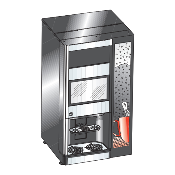
PRODUCT PRESENTATION EXTERNAL CABINET 1- Cabinet 2- Door 3- Touch screen panel 4- Advertising poster 5- Door lock 6- Cup holder (drip tray) 7- Pot platform Fig. 1 12-2015 H0522EN00... -
Page 11: Interactive Gestures
INTERACTIVE GESTURES To navigate and interact with the equipment, the following interactive gestures are required: Tap icons, features and objects to activate or open contextual menus. movE DrAg To move / drag icons and objects touch and move / drag to another location. sCroLL Slide the finger on the touch screen to the right, left, up or down to scroll through the values, screens and functions. -
Page 12: Peration In Normal User Status
OPERATION IN NORMAL USER STATUS The representation and arrangement of icons/screens in this manual is approximate and may vary from the one displayed on the machine depending on the configuration (layouts, themes, and/or icons) In normal operation, the machine displays the screen with the available selections. -
Page 13: Request Beverage
REQUEST BEVERAGE Therefore, to: Touch the desired beverage. bEvErAgE IN THE CuP The screen with beverage customizations is displayed - Place the cup under the nozzles - Customize the beverage according to your taste - Touch the “Dispense” button - The beverage is dispensed fILL A jug - Place the pitcher under the nozzles - Customize the beverage according to your taste... -
Page 14: Machine Status
MACHINE STATUS When the drink is being dispensed, a screen with the animation indicating the stage of preparation of the beverage is shown. You can view the status of the machine (eg residue containers Touch the entertainment icons to change the displayed content level, containers level, ...) using the status panel. -
Page 15: Machine Cabinet
MACHINE CABINET Fig. 5 1- Outlet spout 2- Mixing funnel with whipper housing 3- Mixing funnel hood 4- Cash box (option) 5- Retaining pin for cup carrier 6- Drip tray 7- Heating element cover 8- Nozzle 9- Instant ingredient canister 12-2015 H0522EN00... -
Page 16: Aintenance
MAINTENANCE MAINTENANCE ROUTINES Interval Type of work / Check Tools / Materials for the job Regular: Opening and disconnecting the machine 1 bucket of hot water (60-80°C) with cleaning Every time replenishing Removing the waste containers agent. of ingredients is required Filling the instant ingredient canisters 1 bucket of clean warm (min. - Page 17 Interval Type of work / Check Exchange kit (hygiene kit) Occasional Cleaning the instant ingredient canisters. Once a month Cleaning the coffee bean canister. 12-2015 H0522EN00...
-
Page 18: Weekly
Fig. 6 Fig. 7 Fig. 8 Remove waste bucket and lower plate, WEEKLY rEPArINg for fILLINg of CANIsTErs empty coffee waste. Clean all the remo- ved parts and the base of the machine PENINg AND DIsCoNNECTINg mACHINE with a sprayed wipe. Remove lower drip tray and the upper Turn the door key clockwise in keyhole plate, clean the parts with a sprayed... - Page 19 Fig. 11 Fig. 9 Fig. 10 Pull up instant canister outlets. Reset drip tray counter. Tap “Empty solid ILLINg THE INsTANT INgrEDIENT waste”. CANIsTErs Remove sugar caniste (optional): turn it up pull it outward. Put it on a talble. 12-2015 H0522EN00...
- Page 20 Fig. 13 Fig. 12 Put canisters on a table, open lids then LEANINg DrIP TrAy uLL uP ProDuCT ouTLET THEN fill them with products. Clean outside Unscrew the knurl that fix external drip canisters before place them back into rEmovE IsTANT CANIsTEr oNE AT tray, clean external drip tray with a wet machine.
-
Page 21: Deep Cleanings
Fig. 14 Fig. 15 Fig. 16 Remove mixing bowls and pipes, Remove water nozzle. DEEP CLEANINGS exhaust system area and mixer plates. LEAN ALL THE oTHEr PArTs Remove head of mixing bowls, spray into the m, clean with wipe and replace the head of mixing bowls. - Page 22 Fig. 17 Fig. 18 Dry the parts accurately: head of mixers, Unscrew the knurls that fix nozzle sup- Wash parts using cleaning materials, exhaust system parts, funnell for coffee ports to frontal bar. finally wash with clean water. powder and brewer. Reassemble dried parts.
- Page 23 Fig. 19 Fig. 21 Fig. 20 Clean internal and external side of the INsINg mACHINE Chose the to be rinsed then press OK. door with wet wipe. For rinsing: close the door (or simulate door closing by placing the yellow key into its slot) select “Wittenborg”...
- Page 24 Fig. 22 Fig. 23 Clean the whole cabinet with wet wipe. Fill in the HACCP documentation book. Remove the yellow key, close the door and start up. 12-2015 H0522EN00...
- Page 25 Important ENErAL INsTruCTIoNs Never touch the adjusting knob Before starting any adjusting operations of the grinder. Always call a requiring technician for adjustment / parts of the unit to be removed, the calibration of grinder! machine must always be switched off. - The operations described in the pro- The grinder requires a period ceeding pages should be carried out...
- Page 26 - ELECTRIC PANEL To access the electrical panel, remove the instant products containers. Remove the containers and the metal cover to access the com- ponents of the electrical panel. The fuses are accessible from the door of the electrical panel cover.
-
Page 27: Activation Board
ACTIVATION BOARD Board is powered in 24 V. Power is supplied from the power supply board. The board is placed in the electrical panel of the equipment and manages: - the activation of the various users. - sensors control signals (level, presence,...) The LEDs indicate: - DL1 (18) green LED - DL2 (30) green LED flashes during normal operation... - Page 28 Fig. 25 1- (J11) Boiler control board / boiler sensor 2- (J14) Top panel switch 3- (J16) Coin mech engine 4- (J6) Fan / level sensors power supply 5- (J15) Not used 6- (J18) Motor-dispensers / grinding adjustment engine 7- (J9) Vibration pump 8- (J8) Grinder / coffee release electromagnet R202 R208...
-
Page 29: - Touchscreen
TOUCH SCREEN CPU BOARD rELAy fuNCTIoN Board is powered in 24 V. user Power is supplied from the power supply board. Grinder The board is placed on the door and manages: Coffee release electromagnet (if present) - touchscreen Grinder 2* - payment systems (if present) Coffee release electromagnet 2 (if present)* - mechanical stroke counter (if present) - Page 30 Fig. 26 18 19 20 21 1- (J16) 24 Vdc Power supply 2- (J14) Not used 3- (J7) Not used 4- (J25) Not used 5- (J17) Not used 6- (J26) Not used 7- (J10) Not used 8- (J29) can bus 9- (J21) Ethernet connector 10- (JP3) jumper ..
- Page 31 ofTwArE uPDATE The device software can be updated with a USB stick or via remote connection (for networked equipment). The software is updated from the programming menu. uPDATE vIA usb - Insert the USB stick with the new software - Tap “browse” to open the navigation window of the USB stick file system - Select the file with the software update.
-
Page 32: Power Supply Board
POWER SUPPLY BOARD Board is powered with 230 V∿. The board provides power to the control electronics (24V) and the touch screen The board is placed in the electrical panel of the equipment Fig. 27 1- (J2) 24Vdc connector 2- (J1) 230Vac power supply connector 12-2015 H0522EN00... - Page 33 12-2015 H0522EN00...
-
Page 34: Boiler Control Board
BOILER CONTROL BOARD The board controls the activation and deactivation of the heating elements of the boiler. Fig. 28 1- (J1) board control connector 2- (J2) boiler heating element supply connector. 12-2015 H0522EN00... - Page 35 Appendix 12-2015 H0522EN00...
-
Page 36: Electrical Diagrams
ELECTRICAL DIAGRAMS * rated voltage may be also 220V 60Hz Mod1 F 230-240V* Inst Sheet 2/2 N 230-240V* X1.1 MF4 MF3 24Vdc J2-8 J1-1 X1.2 0Vdc 24Vdc 230-240V J2-3 J1-2 24Vdc X1.11 J1-3 J2-7 CAN_H X14.1 X1.10 0Vdc 50Hz* J2-2 X1.4 7 70 Salim... - Page 37 MOTOR CAM CM1-.. COFFEE UNIT MOTOR CAM COIN RETURN CAM VOLUMETRIC COUNTER WATER INLET SOLENOID VALVE COFFEE DISPENSING SOLENOID VALVE ESC1-. COFFEE RELEASE ELECTROMAGNET EV1-.. INSTANT SOLENOID VALVES EVH2O WATER SOLENOID VALVE RADIO INTERFERENCE SUPPRESSOR MOTOR CONTROL SWITCH ID1-.. COFFEE DOSE SWITCH MAIN SWITCH FULL WASTE SWITCH TOP PANEL SWITCH...
- Page 38 24Vdc Scheda Irda 3 +5V 8(5) 8(5) X13.6 FREE pres X13.5 8(2) 8(0) VEND 8(8) X13.4 cassa 8(8) X13.3 X13.2 8(5) X13.1 8(0) X15.1 8(4) X15.2 8(6) X15.4 X15.3 8(9) 8(10) 8(1) 8(3) 8(7) X12.5 X1.10 24Vac X12.6 X1.9 1615 X12.10 8(15) X12.11...
- Page 39 BDV COIN MECH CONNECTOR GENERAL COUNTER EXECUTIVE COIN MECH CONNECTORS FREE FREE VEND SWITCH IRDA IRDA BOARD JUG FACILITIES SWITCH MDB COIN MECH CONNECTOR RS232 SERIAL PORT SALIM POWER SUPPLY UNIT BOARD SLED LED BOARD MACHINE BOARD C.P.U. BOARD CUP SENSOR 12-2015 H0522EN00...
- Page 40 12-2015 H0522EN00...
-
Page 41: Hydraulic Circuit
HYDRAULIC CIRCUIT moDEL Fig. 29 1- BOILER 2- MIXER SHELF 3- INLET VALVE 4- RE-CIRCULATION VALVE 12-2015 H0522EN00... -
Page 42: Hydraulic Circuit
HYDRAULIC CIRCUIT CAbINET 1- SUCTION PUMP 2- TANK 3- LIQUID WASTE CONTAINER 4- TO THE DEVICE 5- LIQUID RESIDUE CONTAINER DRAIN PIP Fig. 30 12-2015 H0522EN00... -
Page 43: Access To The Programming Menus
programming ACCESS TO THE PROGRAMMING MENUS. To access the menu of the machine (with the door closed) tap Below are the available functions. and hold for 3 seconds the logo at the top left of the selections Those that are not used for the specific model layout, or which screen. - Page 44 sEArCH fIELD Allows to search for the function by name. Tap to view the keyboard. Type the name of the function, the functions that contain the typed text are displayed while typing. From the search results displayed, touch the desired function. NAvIgATIoN sIDE mENu Shows the functions available for the current user profile and the “next / back”...
- Page 45 fAvourITEs ICoN kEyPAD The “favourites” are shortcuts to frequently used functions. Use the keypad to enter the password to access the menu ac- After a function is added to the “favourites”, it will be enough to cording to the user profile. view the “favourites”...
-
Page 46: Entering The Values
ENTERING THE VALUES mEssAgE ArEA Displays some information, such as statistics on the most The values in the programming menu can be entered / modi- popular selections, ... fied as follows: fAuLT ArEA EyboArD Displays the machine faults. mAINTENANCE INformATIoN ArEA Displays information about the deadline for the maintenance Buttons : - “Maintenance notice”: sets the current date/time as the date... - Page 47 EyPAD DowN LIsT Tap to open the drop-down list and select the value. Fig. 33 Fig. 35 1- Confirm the values 2- Delete the last number entered (back space) ALuE PICkErs 3- Cancel the entered values and closes the keyboard Scroll to select the desired value HECkbox Tap the checkbox to enable/disable the option.
-
Page 48: Daily Actions
soLID rEsIDuE CoNTAINEr DAILY ACTIONS Resets the counter which handles the reporting of “residues Includes all the functions that affect daily operations (washing, full” of the solid residue container. residue counters reset, …) To ensure the right management of the warnings, you must reset the counter any time the solid residue con- wAsHINg tainer is emptied. -
Page 49: Selection Settings
EDIT bEvErAgE SELECTION SETTINGS From the screen you can: LAyouT DIsPLAy - Change the name of the beverages displayed in normal op- Select the layout of the selections displayed in normal opera- eration tion from the default ones. - Define which recipe to use for the beverage. You can also change the order of the selections simply by drag- ging the selection icon to the new position. - Page 50 - set the capacity of the cup used to obtain a representation rECIPEs indicative of the quantity of beverage in the cup. You can: If the amount of the beverage exceeds the set size of the cup, - Change the recipes of the selections (used, available, and an error message is displayed.
- Page 51 To edit the settings of individual products (for example amount EDIT rECIPE of water, powder, ...): From the recipe screen you can: - tap the bar corresponding to the product (such as milk, - change the name of the recipe chocolate, ...) to change the basic and advanced parameters.
- Page 52 bAsIC PArAmETErs EsPrEsso ADvANCED PArAmETErs You can set: INITIAL DELAy - the name of the ingredient Set a time delay of the ingredient; the delay is useful if recipes composed of multiple ingredients are created. - water dose For example, when creating the recipe “Espresso with milk” a - add / remove an ingredient time delay between the dispensing of espresso and milk can be set.
- Page 53 squEEzE DowN forCE INfusIoN DosE sets the coffee cake squeezing force exerted by the top piston Sets the amount of water (ml) to be used during the pre-infu- at the end of dispensing. sion. squEEzE rEsT forCE INfusIoN TImE it sets the safety value of the coffee cake squeeze down force. Sets the pre-infusion time before the infusion.
- Page 54 frEsH brEw ADvANCED PArAmETErs squEEzE sTArT This parameter (in % of the delivery time) allows to establish for INITIAL DELAy how long the infusion takes place at low pressure (freshbrew) Set a time delay of the next ingredient; the delay is useful if and how long at high pressure (espresso.) recipes composed of multiple ingredients are created.
- Page 55 ALvE oPEN PErIoD LImIT TACHo vALuE It sets how often to open the FB valve to lower the extraction It sets the height of the upper piston in the chamber during infu- pressure. sion at low pressure (fresh brew) Default value 430. ALvE oPEN DuTy A value close to 1023 indicates that the upper piston is very Only for fresh brew selections.
- Page 56 INsTANT ADvANCED PArAmETErs IxINg sPEED mEDIum HIgH You can define the mixing speed according to the product qual- INITIAL DELAy ity you wish. Set a time delay of the ingredient; the delay is useful if recipes composed of multiple ingredients are created. wATEr quEuE For example, when creating the recipe “Chocolate with milk”...
- Page 57 - Calibrate the instant beverages and pre-ground coffee motor- INgrEDIENT CANIsTErs doser. According to the machine layout, it displays the screen with the The calibration allows to adjust the working speed of the product containers. motor-doser to define the capacity in g/sec. You can enter nutritional information and a picture (such as a To calibrate, proceed as follows: logo,...) for each ingredient.
-
Page 58: Machine Settings
mECHANICAL LAyouT MACHINE SETTINGS It is the mechanical layout of the configuration used by the equipment. CoNfIgurATIoN It shows the arrangement of the containers and main functional groups. sELECT CoNfIgurATIoN You can indicate to the software the new mechanical settings of Allows to manage the configuration provided by the software of the equipment. - Page 59 rECovEry ExPorT To usb Allows to recover machine settings from a backup file. Allows to export machine settings to a saved configuration file. The device can be reset to: Warning !!! - factory settings Export can be used to clone current settings to another - custom settings previously saved.
- Page 60 grAPHIC PErsoNALIzATIoN DIsPLAy sETTINgs Enables / disables the view of the following: EDIT moDIfy - number of dispensed beverages at machine start up. Allows to set some user interface graphics such as Logos, - price of the selections in normal operation icons, colours, ...
- Page 61 rss fEED AND wEATHEr INPuT sENsors sETTINgs in normal operation and during the delivery of the selection, The function group allows to set the operation of some of the you can watch the rss feed (news) and weather reports. equipment sensors. To watch the news and weather reports, the machine must be CoNTAINErs LEvEL connected to the Internet.
- Page 62 soLID wAsTE ALIbrATIoNs Enables / disables the solid residue count that manages the fLow mETEr CALIbrATIoN “residues full” warning. The flow meter calibration allows to obtain the correct amount - Set the maximum capacity of the solid residue container; the of water provided from the recipes.
- Page 63 - Calibrate the instant beverages and pre-ground coffee motor- INgrEDIENT CANIsTErs doser. According to the machine layout, it displays the screen with the The calibration allows to adjust the working speed of the product containers. motor-doser to define the capacity in g/sec. You can enter nutritional information and a picture (such as a To calibrate, proceed as follows: logo,...) for each ingredient.
- Page 64 ouTPuT CoNfIgurATIoN fAN sETTINgs Enables / disables the continuous operation of the steam suc- INfusEr uNIT tion fan. - Empty coffee: a sensor detects the rotation of the grinder - OFF: the fan is activated only during the preparation of bever- during the grinding;...
- Page 65 mAINTENECE The machine can be supplied by mains or internal tank. wAsH rINsE With this function you can define whether the device is pow- You can enable / disable the machine automatic rinse cycle ered from the mains (tank = OFF), from tank with water level programming.
-
Page 66: Machine Information
boILEr PArAmETErs MACHINE INFORMATION - Temperature: sets the operating temperature of the boiler fAuLTs - Minimum temperature for dispensing beverages: sets the The machine has a number of sensors for keeping the various minimum temperature to enable beverages functional groups under control. With the parameters “Temperature Threshold”... - Page 67 1...6 ( EvENT HIsTory AuLTy mIxEr wHIPPEr fAuLT This function allows to view and filter the events recorded from If the current absorption of a mixer motor is not between the the equipment by: range of default values, all the selections in which that mixer is involved are disabled.
- Page 68 oLumETrIC CouNTEr offEE uNIT fAILurEs No counting of the volumetric counter within a maximum time. The position control microswitch of the coffee unit is read dur- ing the whole dispensing cycle. wATEr LEAkAgE According to the micro readout and the dispensing phase of the unit, any failure is declared by locking the selections based The Air-break micro switch signals the lack of water without a on espresso coffee.
- Page 69 wAsHINg of THE EsPrEsso uNIT wITH TAbLETs offEE uNIT DIsCHArgE uNIT fAILurE At the end of the brewing phase, the control micro signals that Reports the need to wash the espresso unit using sanitizing the coffee unit has not reached the “used dose discharge” posi- tablets.
- Page 70 CoIN mECHANIsm DrIP TrAy NoT PrEsENT The machine stops if it should receive an over 2-sec. pulse The liquid residue container does not operate the micro switch on a validator line or if the communication with the serial coin indicating the presence of the container. mechanism is not longer than 30 seconds (Executive protocol) Check that the liquid residue container is correctly positioned or 75 seconds (BDV protocol).
- Page 71 1...7 ATEr Low PrEssurE EmPTy DosEr the pressure switch detects low water pressure inside the The minimum level of instant powder in the container associ- machine. ated with motor-doser has been reached. The signal is active if they controls on instant powder contain- rINDEr sHuTDowN ers are activated.
- Page 72 1...2 EmPTy EsPrEsso DIsPENsEr sTATIsTICs The minimum level of coffee beans in the container has been sHow sTATIsTICs reached. Displays statistics on selections The signal is active if they controls on coffee beans containers Displays selections statistics showing: are activated. Check the level of coffee beans in the containers.
- Page 73 fAvourITEs mACHINE ID The “favourites” are shortcuts to frequently used functions. Allows you to enter a number and the name that identifies the After a function is added to the “favourites”, it will be enough to machine. view the “favourites” and touch the function for quick access. The code can be used for the identification of the machine for the analysis of the statistics.
-
Page 74: Energy Saving
“ ” DEEP moDE ProfILE ENERGY SAVING This profile is active on the set time frames. The energy saving function allows to enable, change the In the set time frames, the boiler temperature is lowered and parameters, and set the time frames of the machine energy the maintenance temperature is set. - Page 75 TImE bANDs Allows to set the energy saving profiles time frames. - Tap the day when to set the time frames. - Tap “+” and then touch the line corresponding to the profile to place a rectangle with the indicated time. - Drag the rectangle to define the exact time.
-
Page 76: Payment Systems
ECImAL PoINT PosITIoN PAYMENT SYSTEMS To set up the decimal point position, i.e.: You can decide which protocols to enable for the payment sys- decimal point disabled tems available and manage the relative functions.. XXX.X (one decimal digit after the point) Some parameters shared by several payment systems keep XX.XX (two decimal digits after the point) the set point even if you change the type of system. - Page 77 xECuTIvE oIN mECHANIsm vErsIoN mmEDIATE CHANgE You have to choose among the following payment systems for The amount relative to a selection is generally cashed after the the Executive system: machine has sent the “Successful selection” signal. If you enable this function, which is disabled by default, the - Standard cash signal is sent at the start of the dispensing cycle.
- Page 78 rEDIT rETurN EsCrow LEvEr oINs ACCEPTED for CHANgE To enable/disable the credit return (by pressing the change To program the refusal of a coin in case of “exact amount”. return key) if no dispensing has been performed. For the coin/value correspondence check the label showing the If enabled, this function will provide for the return of the coins position of the coins on the coin mechanism.
- Page 79 IsTrIbuTIoN buTToNs Use this function to enable or disable the buttons arranged mmEDIATE CHANgE on the coin mechanism in order to discharge the coins in the The amount relative to a selection is generally cashed after the change tubes. machine has sent the “Successful selection” signal. C.P.C.
- Page 80 yPE of DIsPENsINg CCEPTED CoINs To set the operation mode by multiple or single dispensing. In To define which coins shall be accepted among those recog- case of multiple dispensing, the change is not automatically nised by the validator when the change tubes are full. given at the end of a successful delivery, but the credit will For the coin/value correspondence check the coin mechanism remain available for further dispensing.
- Page 81 ILLs ACCEPTED for ExACT CHANgE sALE CommAND To define which bills shall be accepted among those recog- The function is used to give evidence that cash transactions nised by the reader when the machine is in the “exact amount” have occurred by means of a cashless system. mode.
- Page 82 For example: the “10” equation will display the “No change” xACT CHANgE EquATIoN message when all four tubes have achieved the minimum level. To choose among 15 different control algorithms to enable the The “04” equation will display the “No change” message only machine to give the change at the end of the selection.
- Page 83 PrICEs ILL rEADEr fuNCTIoN bILL rEvALuE To enable the bill reader only to recharge the credit on the urrENCy symboL cashless system (key or card). NDEfINED CrEDIT CAsH Set up the currency symbol during the credit display. This function is intended to accept cashless payment systems (key or card) or not if the cashless system credit is not defined.
-
Page 84: Import / Export
IMPORT / EXPORT SYSTEM Includes all the functions to export and import statistics, ma- ComPoNENTs TEsT chine settings, graphics packages, … Allows to check the main components of the machine. EvADTs The components that can be checked are displayed. Allows export EVADTS data to USB stick and/or serial. Tap the component to be tested on the touch screen. - Page 85 sENsors AND INPuT DEvICEs TEsT boILEr fILLINg AND EmPTyINg A screen appears with the status of the equipment control You can fill and empty the boiler. devices (sensors, microswitches,...). The hydraulic circuit filling is automatic. The status of the ON/OFF devices is shown in green if the In case of maintenance at the hydraulic circuit or if one were to device is active/enabled, in red if inactive/disabled.
- Page 86 boILEr EmPTyINg mACHINE PArAmETErs TEsT Sets the activation time of the components during the self-test. The boiler must be emptied by technical personnel. ACTory rEsET The boiler water is very hot and causes burns. Allows to restore the device to factory settings. Before emptying the boiler, wait for the water in the boiler Warning !!! to cool down.
- Page 87 DATE TImE usEr ACCEss Date and time are used to record events (for example faults, You can enable/disable some programming functions using ...), for the management of programmed wash and for mainte- some access profiles. nance warnings. Access profiles ensure that only certain functions assigned to Set current date and time.
- Page 88 NETwork NETwork Allows to enable and configure the wi-fi connection of the ETHErNET equipment. Allows to enable and configure the network card of the equip- The equipment supports leading wi-fi security protocols. ment. Enter the identifier of the Wi-Fi network (SSID) to connect to. The device supports TCP/IP.
- Page 89 bLuETooTH sofTwArE uPDATE Shows the software version of the machine. Allows to enable and configure the Bluetooth connection and It also allows to update the machine software with a USB stick exchange data (short distance) between the equipment and or via network connection. other devices.
- Page 90 INTErNET uPDATE Only for devices set for internet connection. You can update the machine software via connection to an FTP server with software updates available. Enter: - the address of the FTP server with software updates - the credentials for access to the FTP server (username and password).
Need help?
Do you have a question about the Instant Omni and is the answer not in the manual?
Questions and answers