Advertisement
QPA-1
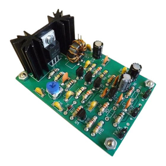
QPA-1 Low level input QRP HF Amplifier
and CW TX (3 a 30MHz)
Assembly manual
Last update: May 1, 2018
ea3gcy@gmail.com
:
www.ea3gcy.com
Most recent updates and news at
QPA-1
kit
Thanks for constructing the
Amplifier
Have fun assembling it and enjoy QRP!
73 Javier Solans, ea3gcy
QPA-1 Low level input QRP HF Amplifier and CW TX (3 a 30MHz)
Page 1
Advertisement
Table of Contents

Summary of Contents for EA3GCY QPA-1
- Page 1 Most recent updates and news at QPA-1 Thanks for constructing the Amplifier Have fun assembling it and enjoy QRP! 73 Javier Solans, ea3gcy QPA-1 Low level input QRP HF Amplifier and CW TX (3 a 30MHz) Page 1...
-
Page 2: Specifications
Terminal-pins 2 + 2 + 2 + 2 Spacers+screws+nuts Hex spacers + M3x4 screws + M3 nuts Heatsink RD756 Heatsink for Q6 (Power Amp) QPA-1 PCB QPA-1 board QPA-1 Low level input QRP HF Amplifier and CW TX (3 a 30MHz) Page 2... - Page 3 There are two important things which need to be done to insure successful operation of a kit. The first is to put the component into the proper place on the circuit board; the second is good soldering. QPA-1 Low level input QRP HF Amplifier and CW TX (3 a 30MHz) Page 3...
-
Page 4: Recommended Assembly Sequence
4.- Place and solder Q1 to Q5 transistors in place printed on the board. Your printed silhouette should match the body of the transistor. Q6-Q7 will be installed later. QPA-1 Low level input QRP HF Amplifier and CW TX (3 a 30MHz) Page 4... - Page 5 - Using a multimeter in its ohm or continuity function, locate and mark the ends, identifying them as “a” - “a1” and “b” - “b1”. - Mount the toroid into the appropriate holes as marked on the circuit board. QPA-1 Low level input QRP HF Amplifier and CW TX (3 a 30MHz) Page 5...
- Page 6 MOUNTING THE POWER TRANSISTOR Q6 The printed circuit board of the QPA-1 allows the placement of two different MOSFET transistors: Q7 and Q6. The place of Q7 is for an IFR510 or equivalent and the place of Q6 is for an RD16HHF1.
- Page 7 If you are going to use the QPA-1 every day as an amplifier or as a CW transmitter with output powers of more than 5W, we recommend using a larger radiator or fasten the transistor directly in the metal box.
- Page 8 (it feeds the "Idle" of the Q6 and should not be present while the transistor is not working). - If the QPA-1 is used as a CW transmitter, then the jumper terminals "TX/K" will be connected to the telegraph key and the input signal can remain connected even if it is not transmitting.
-
Page 9: Limited Warranty
Please, BEFORE returning a product, request instructions by email at: ea3gcy@gmail.com Javier Solans, EA3GCY, warrants this device to function according to the specifications, provided that it is assembled and adjusted as described in this documentation, and used correctly according to all provided instructions. - Page 10 SCHEMATIC QPA-1 Low level input QRP HF Amplifier and CW TX (3 a 30MHz) Page 10...
Need help?
Do you have a question about the QPA-1 and is the answer not in the manual?
Questions and answers