
Subscribe to Our Youtube Channel
Summary of Contents for Meyer LD-3
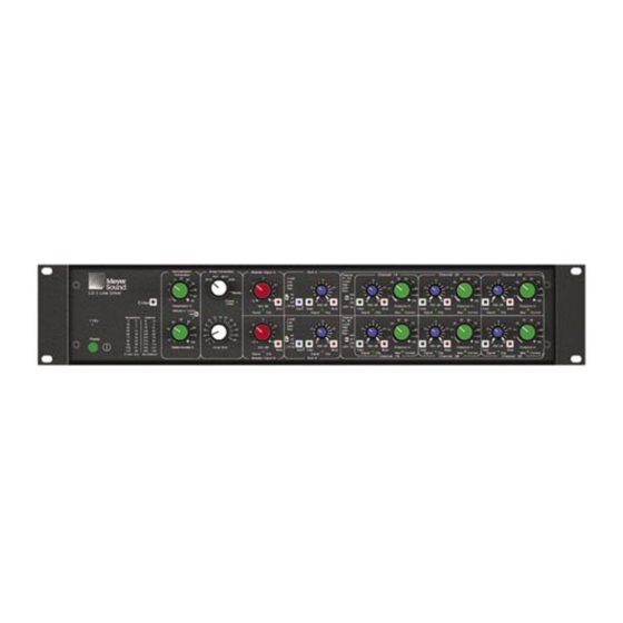
- Page 1 OPERATING INSTRUCTIONS LD-3 Air Attenuation Compensating Line Driver Keep these important operating instructions. Check www.meyersound.com for updates.
- Page 2 Meyer Sound. Meyer Sound, Meyer Sound MAPP Online, SIM and QuickFly are registered trademarks of Meyer Sound Laboratories Inc. (Reg. U.S. Pat. & Tm.
-
Page 3: Important Safety Instructions
2. Keep these instructions. 12. Use only with the caster rails or rigging specified by 3. Heed all warnings. Meyer Sound, or sold with the apparatus. Handles are 4. Follow all instructions. for carrying only. 5. Do not use this apparatus near water. -
Page 5: Table Of Contents
CONTENTS INTRODUCTION How to use this manual Introducing The LD-3 Air Attenuation Compensating Line driver CHAPTER 1: AC Power Requirements CHAPTER 2: Audio and System Controls Audio Input Atmospheric Correction Temperature Altitude Relative Humidity Array Correction Array Type Array Size... -
Page 7: Introduction
Atmospheric Correction and Relative Humidity knobs, dial-in the type of loudspeakers and distance of the throw for each section of the array, and the LD-3 goes to work. A RISC microcontroller retrieves response correction coefficients and corrects the output to compensate for the air absorption for those weather conditions. - Page 8 Set the type of loudspeaker being used and the number of a main system into subsystems, they can also be cabinets in the array, and the LD-3’s stored presets do the used to control downfill, front fill, and delay systems, rest.
-
Page 9: Chapter 1: Ac Power Requirements
The LD-3 must have the correct power cord for the AC power in the area in which it will be used. The LD-3 operates in two AC voltage ranges: 105 – 125 V and 210 – 250 V, at 50 or 60 Hz (Figure 1.1). The voltage select switch on the rear panel must be set to the proper voltage before applying AC power. - Page 10 CHAPTER 1...
-
Page 11: Chapter 2: Audio And System Controls
CHAPTER 2 CHAPTER 2: AUDIO AND SYSTEM CONTROLS Much more than a system integration tool, the LD-3 line driver uses its sophisticated circuitry to bring consistent and predictable results to any M Series line or curvilinear array design. This chapter will help you understand and harness the power of the LD-3's audio and system controls. -
Page 12: Temperature
(and well beyond the scope of this guide). Although it’s generally true that the LD-3 will boost Figure 2.2. The LD-3 includes a temperature conversion reference frequencies (particularly high frequencies) at an increasing table stenciled on its front panel. -
Page 13: Array Type
The gray Array Type selector (the top knob in the Array THE ENTER BUTTON Correction section) is a switch that controls the assignment of the LD-3’s Array Correction function to any of the When the controls in the Atmospheric and Array Correction following M Series loudspeakers: sections are adjusted, press the illuminated Enter button ... -
Page 14: Master Input Channels A And B
These filters are used to optimize integration with Relative Humidity to 40%, press Enter, then change the subwoofers; in several cases they can augment an array’s Temperature to 30°; press Enter again for the LD-3 to headroom by filtering low frequencies out. register the new temperature. -
Page 15: Distance Control
Low-frequency headroom decreases. The length of the line or curvilinear array column is effectively shortened. Figure 2.8. The LD-3 includes an easy distance conversion reference table stenciled on its front panel. Setting the Distance enables the LD-3 to adjust the... -
Page 16: Insert Switch
(Sends), with a Meyer Sound CP-10 complementary phase parametric equalizer. Figure 2.10. The LD-3’s back panel showing Sends and Returns for Figure 2.11. The LD-3’s sub section 1-3, A & B; a CP-10 can be added to the signal processing chain... -
Page 17: Insert Switch
The Insert/Returns are not affected by the array correction, but are affected by the Low-Pass Filter. The Sub section’s inserts have a summing stage. If not engaged, the LD-3 will sum the signal from the main input with the signal from the Insert input. - Page 18 CHAPTER 2...
-
Page 19: Chapter 3: System Design, Integration, And Optimization
CHAPTER 3 CHAPTER 3: SYSTEM DESIGN, INTEGRATION, AND OPTIMIZATION The LD-3 opens up a number of design and integration You can find MAPP Online at: scenarios. Its versatility, in conjunction with different M www.meyersound.com/products/software/mapponline Series loudspeakers and/or subwoofers, gives you the... -
Page 20: Loudspeaker/Subwoofer Integration
However, the use of external filters – like the ones in the LD-3 – is optional, and should be used very carefully to avoid phase shifts that can cause cancellations or dips in the response. -
Page 21: Sim® Measurement System
SIM® MEASUREMENT SYSTEM equalization Optimizing subwoofer integration Meyer Sound also offers a self-contained design and troubleshooting package: the SIM Measurement System. Optimizing loudspeaker arrays SIM is a measurement and instrumentation system... - Page 22 CHAPTER 3...
-
Page 23: Appendix A: Specifications
Sub Insert. Sends and Inserts operate 3dB lower than Master signal, therefore signals applied to Sub Insert XLR will have 3 dB greater gain through LD-3. Signal/Clip Indicator Glows green with signal and red when output is in clipping OUTPUTS: CHANNELS 1-3 (A&B) - Page 24 APPENDIX A INPUT CONNECTORS Master A & B 2 Female XLR; 1 per input channel Insert/Return Sub Input 2 Female XLR; 1 per input channel Channels 1-3 (A&B) 6 Female XLR; 1 per input channel; Insert is Pre-Atmospheric Correction / Post-High Pass Filter/Crossover AUDIO OUTPUTS Type Balanced, cross-coupled simulated transformer topology...
-
Page 25: Appendix B Example Configurations
APPENDIX B APPENDIX B Example Configurations LD-3 Channel A SUB OUT CH 1 OUT CH 2 OUT CH 3 OUT Channel B SUB OUT CH 1 OUT CH 2 OUT CH 3 OUT Channel A INSERTS SENDS IN SUB Full Range... - Page 26 APPENDIX B LD-3 Channel A Left SUB OUT CH 1 OUT CH 2 OUT CH 3 OUT Channel B Right SUB OUT CH 1 OUT CH 2 OUT CH 3 OUT Channel A INSERTS SENDS IN SUB Full Range IN CH 1...
- Page 27 APPENDIX B LD-3 (10) MILO Main (10) MILO Channel A SUB OUT Left CH 1 OUT CH 2 OUT CH 3 OUT Channel B Right SUB OUT CH 1 OUT CH 2 OUT CH 3 OUT Channel A Subwoofer INSERTS...
-
Page 28: Appendix C: Signal Flow Diagram
APPENDIX C APPENDIX C LD-3 Signal Flow Diagram Signal & Clip GREEN / RED Detector CH 1-3 MASTER CROSSOVER LEVEL ARRAY SIZE RF Filter MAIN Absorber CORRECTION INPUT -12 to +6dB EARTH GND/ EARTH GND/ 80 Hz CHASSIS CHASSIS GREEN /... - Page 29 APPENDIX C SEND 3 Post HPF X-Over Post Array Correction Absorber POWER PUSH-PULL EARTH GND/ OFF MUTE DRIVER CHASSIS (SHORT) EARTH GND/ CHASSIS SIGNAL & CLIP GREEN / RED DETECTOR -6 TO +6 dB ATMOSPHERIC CORRECTION Absorber CHANNEL 1 RF Filter MUTE Absorber CHANNEL 1...
- Page 30 APPENDIX C...
- Page 32 © 2003 Meyer Sound Laboratories Inc. T: +1 510 486.1166 Meyer Sound Laboratories Inc. 2832 San Pablo Avenue F: +1 510 486.8356 All Rights Reserved Berkeley, CA 94702 techsupport@meyersound.com www.meyersound.com...
Need help?
Do you have a question about the LD-3 and is the answer not in the manual?
Questions and answers