Table of Contents
Advertisement
Quick Links
1- Presentation
- You have adquired Gas water Heater, developed to provide hot water without electrical power
consuption. Practival and economical, with automatic activation and pilot flame, to attend your
needs with greater safety and comfort.
2- Atention
- Please red carefully the installation instructions and operation before using de
product. Keep this manual for future references. The installation of this product
should be made by qualified personnel for your entire safety and product life
increasing. L
- The heaters are manufactured to operate by only one type of gas NG (natural gas)
or LPG ( liquefied petroleum gas)
- Its packaging on the lefts side of the layer(fig. 9) shows the identification of what
type of gas must be used. If in case any doubt consult your local dealer.
3- Instalation
-The installation of this product must cumply the standard of your country.
- For specials applications (central heatinf swimming pools,etc) consulting a
qualified technician.
-This manual recommend the installation by a qualified technician.
- The self-installation or by unqualified persons, made without proper care, can
offfer risks compormising prouduct performance.
- Caution: Do not install the producto exposed to the weather without adequa-
te protection against dust, impact of water or other liquids.
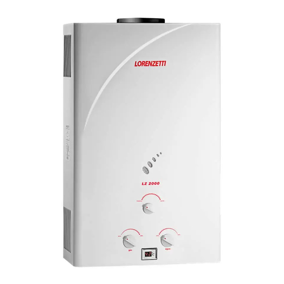
LZ - 2000
LZ - 1600 N
3.1- Gas Connection
INSTANTANEOUS
- Verify if the type of gas supplied is compatible with the product adquired. Before to
GAS WATER HEATER
the installation of the product please check the followings preocedures.
- Certificate that no residued and possibles losses in the gas pipe installation.
- Verifiy if the gas pressure supply is in accordance with the characteristics of the
product (Item 8 Technical characteristics). - Connecting the product to the gas pipe,
INSTRUCTION AND
installing before the product a valve for blocking opening the gas supply (Pic 1)
INSTALLATION MANUAL
07
5.2 -Temperature control
- This heater as a temperature controler to avoid overheating problems, ie, when the outlet
water temperature reaches high values, the heater is automatically switched off and there is no
heating water.
- The controller is reset atomatically .
- To place the product back in operation, close the hot water faucet / tap and then re-open it .
- If the problem continues, do not use it , turn off the product close the valve and get in
contact an authorized technical assitance.
6 - Maintenance
7.- Close the hot water faucet previously opened and open the cold water valve of the pro-
duct*(pic1).
-
IMPORTANT:
-
Whenever you make any maintenance at your heater, the
If the pressurized hydraulic networks, precaution air removal of the pipe then after cleaning
*
removal of the batteries from the compartment is recommen-
the filter. If in doubt, contact a especialized person
ded to avoid unexpected product activation .
- For a proper operation and extended life of the product,
proceded periodic reviews (between 1 and 2 years) at the
product, through the authorized technical assitance.
6.1 - Danger of Freezing
To clean the external cover use a damp cloth and mild soap, do
not use chemical products (gasoline, alchool, thinners, etc.)
If under the local weather where the product is installed there is a possibility that the tempera-
powders or abrasive products. - When replacing parts, always
ture reaches values below zero degrees centrigrade (OºC), the water from the product should
use only original Lorenzetti spare parts.
be drained to prevente irreversible damage at the product.
Clean the filter at water inlet of the product every 6 months or
shorter periods, if necessary proceed as follows:
1.- Close the cold water valve of the product (Pic 1)
2.- Open a hot water tap/faucet to drain the water stored inside
the product and / o pipe.
3.- Remove the water inlet connection of the product. Taking care to place a bucket just below
the product in order to receive the waste heater that eventually may still be inside product
and/or pipeline, avoiding wetting the area around the product.
4.- With the help of an adequated tool( screwdriver, for axample), remove the filter screen
metal placed inside duct inlet water of the product (Pic 7)
5.- Clean the filter, eliminating completely eliminate on the surface any dirt and debris.
6.- Replace the filter on your site connection and water inlet product, certify if the connection
is well fastened to prevent water leakage.
02
-The gas heaters that operate with LPG gas, supply by
cylinders equiped with blocking and flow regulation deviced
must be interconnected to ensure safety conditions to the
people and the place where it is installed.
-The gas supply must be size acoording the flow required by
the product and be provided with all safety and controls
deviced needed.
- If the product is not used for a long pereiod of time, you
should shut off the main valve for safety reasons.
- Do not use gas pipes fro grounding wire the electrical
applianced.
-Check using some soap/detergents foam at all connections
to ensure there are not leakage.
- If necessary change the gas type supply, please request a
technician for proper conversion changing be performed on
the right way.
These products allow the gas exchange rate for NG for LPG and LPG for NG.
**
3.2- Water connection
Provide the installation of a blocking valve in the water inlet point. Before starting the water connecti-
on of the device, open the blocking valve and let run the water to eliminate any air and any debris from
the pipe. (Pic.01)
Looking at the product, the cold water inlet is the right side , the hot water outlet is at the center side
and the gas inlet at the left side (Pic. 2). Be guided by markings on the bottom of
the product
Ensure that your intallations of hydraulic pipes are not being used as grounding
wire for any of your electrical devices or telephone, due to they are not recom-
mended for this purposes. Under these conditions severe damages are subject to
happen at the pipes and the product .
Check if all faucets and valves (for bathing ) closed
Confirm that the pressure of incoming water is under recommendation of the
product (item 8 -Technical Specifications). -
Use a proper treated water
The direct use of water from the mains depends on its constancy supply and adequate pressure
supplied. (see specifications table, item 8). The u
of the product.
In case of the use of water from an artesian well, a craft well please make the proper phisi-
cal/chemical analisys of the waterand only used if it is under the correct standards of supply
network or properly weel treated for consumption.
At the output for showers and mixer taps , install connections type "Y". This ensures a good gperfor-
mance of the product and avoids eventual cuts of in the water supply .
If it is necessary to pressurize the network, perform it at two lines (hot and cold) in order to have a well
balance at water mixture.
For mixer faucet with monocontrol , make sure the pressures on the network (hot and cold water) are
well balanced
08
Aliviate drain valve
7
cold water
inlet
OFF
ON
cold water
inlet
gas inlet
hot water
inlet
inlet
Orientative
filter
drawing
Orientative drawing
6.2 - Removing the front cover of the heater
To Remove thr front cover of the
product, proceed as follows- (Pic. 9):
Socket
1. Remove the buttons "A", "B" and
"C", pulling them forward
2. Unscrew the two screws Philips at
the botton side of the front cover
3. Pull the cover forward and to then
To replace the front cover
up.
upside proceed to disasembling.
Obs.:
Procedure that should be
done by technician
03
2
outlet gases
1
clamp
VERÃO
INVERNO
VERÃO
INVERNO
hot
Gás
cold
water
water
cold water
3.3- Combustion gas exhaustion
hose hot
valve
water
gas valve
For combustion gas exhaustion proceed with the installation following the local lows procedures.
Note: The tube, clamp, register,
The gas heater are provided with connection to the exhaust gas duct and must have a direct connecti-
water and gases hose does nor supplier
on to the individual or collective chimney (pic. 3)
The interconnection of the product to the external environment need to be accomplished through
individual or collective chimney, a pipeline made by appropirate materials, and resistant against
weather , normal mechanical stress, heat and other environment conditions where the product is
installed.
The exhaustion gas duct should not have its diameter reduced to lower measures than specified at
item 8 of this manual (chimney of the diameter)
3.4- Environment ventilation
For the ventilation at the installation point, check your local standards requeriments.
It is forbidden by its danger to operation of vacuum cleaners, and fireplaces similiar in the
same place where the products installed.
The environment where the product is installed must be provided regular input of oxygen to
ventlitation and shall have:
1) Permanents openings at the wall to communicating with the outside.
2.Ventilation duct (individual or collective) in case where there is such a need .
4- Batteries installation
The two batteries of 1.5V (batteries size big type
D ), must be positioned in the compartment
se out of these conditions can results to damage
located in the button part of the product (fig. 5).
The batteries are not provied with the product.
Observ the batteries polarity. Use a alkaline
batteries. In case the batteries are no being used,
at long period of time, remove them.
Batteries should be replaced periodically to
avoid is no ignition problems due to lack of
changing device (see item 7)
09
To drain the water, close the cold
7-Eventualproblemsandrespectivesolutions.
8
water valve supply and completely
Attention: The following checklist should be performed
drain the water from the product,
by a qualified person. In case of doubts, please contact
removing the relief and drain valve
distributor in your country .
(Pic 8) and also the connection of
output hot water of the heater.
Posible Cause
PROBLEM
- Take care to place a bucket just
Batteries expired or bad contact
below the heater to collect the
Ignition cable is loosen
water drained from the product and
pipe, avoiding wetting the region
Electric Circuit is damaged
There is no spark
around the heater.
Insufficient water pressure
- After draining, replace relief and
Magnetic sensor damaged
drain valve and the output connec-
Electrode damaged
tion of hot water, making sure to
fasten properly to avoid water
Switch ON/ OFF an the OFF position
Solenoide stuck
leakage.
Control Device damaged
(gas valve)
The pilot does not
no gas supply
connect even if
Gas supply pressure inadequate
there are aparks
Air in the piping gas
Battery with low charge
9
The pilot is connected
The magnetic sensor is
after the water is turned off
locking the flow
Combustion output in poor
The combustion chamber
or dusty environment
blades get dirty in a
Yellow flame
short period of time
Excessive consumption of gas
Leakage at pipes net.
Gas smells
Combustion Gas circuit obstructed
Smell of burnt gas
Evaporation of the resin
duct the chimney
Lack of power
Ignition connects but
Main faucet of the
water does not heat
shower heads open.
Button "B"
The heater disconnects
Mixer "T" and imbalance
when the cold water is open.
pressure of the network
Button "C"
no gas
Button"A"
The heater disconnects
Identification
during the use
No power at the batteries
product stickers
screws
Reduction in the
Dirt in the filter at the inlet water
volumen of hot water
* This operations can be performed by the user
04
3
Model for the installation of the product in a adequate environment:
Duct
air inlet
deflector
SERVICE AREA
UPPER VENTILATION
GAS HEATER
INLET AIR WITH
DEFLECTOR
GAS HEATER
inverno
verão
mín.
máx.
gás
água
ºC
LOWER
VENTILATION
Atention: For your safety, in case the product is being installed to replace an exis-
ting one in the interior of the bathroom or kitchen, check if the environment is
compliance with the local standards concerning to ventilation, gas exhaustion, as
well as special procedures described in item 9 of this manual.
5- Operation
The gas heaters are appliances supplies the instant hot water.
5
The hot water supply should be made through tap / record specific for this purpose.
Opening the tap, the main burner of the heater turns on and heats the water that runs
Lig.
Desl.
through a coil.
Built-in an electronic circuit powered with 3V (2 batteries AA size - D type ), which ignites auto-
matically the burner always the faucet/ tap/valve hot water is open.
The water gets heat through paassing inside a coil. The lightining control and flame
opresence is made by an electronic system
10
8-Technical Characteristics
LZ - 1600 N
LZ - 2000
Tecnical Characteristics*
GN GLP
GN GLP
Solution
342,57
Power consuption in normal conditions
(kcal/min)
342,57
479
Replace or adjust contacts*
(15º C e 101,33 kPa (760 mmHg))
(kW)
26,0
24,6
33,4
Connect the wires
Efficiency about P.C.S.
(%)
84
87
83,0
Replace
Flow capacity by temperatura elevation 20ºC
flow
(l/min)
15,5
15,0
20,0
Check hydraulic installation to pressure guarantee *
standard conditions (15°C e 101,33 kPa (760 mmHg)
flow
(l/min)
2,5 a 7,5
2,5 a 7,0
Minimum conditions for a ignition **
Replace
***
pressure
(mca)
1,5 a 3,5
1,0 a 2,0
Replace
Water maximum pressure
(mca)
80
connect the switch at ON
Time of ignition of safety valve to start
(s)
1,0
unlock solenoid
Replace
GN
(m³/h)
2,26
----
3,02
Gas consuption at the standard conditions
G.L.P.
(kg/h)
15°C e 101,33 kPa (760 mmHg)
------
1,74
------
Open the valve checking for lack of gas *
Inlet gas pressure of the product
(mmca)
200
280
200
Provide adequate gas pressure
Batteries for the ignition ( D type)
(V)
1,5
Make the elimination of air
hidraulic
Heater connections
(pol.)
½" BSP
Replace the batteries *
gás
Replace the flow sensor
Dimensions
Height (A)
(mm)
610
610
Check the efficiency of the
chimney output of combustion gases
Diameter of de chimney ( C )
(mm)
125
125
Check the type of gas and clean the burner
Width(D)
(mm)
350
350
Check and regulate it
Depth (E)
(mm)
190
190
Verify the tube (test with soap foam)
Do not operate electrical switches or any
object that causes spark
*
Gross we Weight
(kg)
14,20
14,20
Check the efficiency of the chimney and
Net Weight
(kg)
12,50
12,5
duct output of the combustion gases.
Reducing the power of the
heater, open the windows *
*Subjetc to change without notice
Regulate the buttons A and B *
**Values minimum flow and pressure depend on the position
Close the main faucet personal
that fits the "B" (fig. 6).Values
showers after the use*
Reduce the heater power
and open less cold water *
*** Minimum operating pressure measured according to
NBR 8130 no load loss (this value may vary according
verify the supply *
to the hydraulic system of residence.)
Replace de batteries *
Cleaning the filter (verify item 6)*
05
5.1 - Using your equipment
The water temperature control can be done at three different ways.
1)
Through the gas control buttons
.
4
Button A
-
Turning it clockwise, you get more gas.Turning it counter clockwise, you get less
gas, consequently, higher or lower temperature of hot water
Button B
-
For comfort and adjusting option, this button allows more precise control of
hot water temperature . At the winter position is higher heating capacity and at summer
position lower heating capacity. Using this control at the summer position is suitable for
warmer days
Button C
- Turning it counterclockwise, you get increased water supply, turning
clockwise is obtained consequently reduced water supply, higher or lower temperature hot
water.
2)
By using the mixer or control the flow of hot water at the point of use. (through the
main register)
You can control the temperature ( high water flow, means lower temperature or vice versa).
In the case of mixer usage , open to hot water and then gradually open the cold water faucet ,
until reaching the desired water temperature. In order to save gas, just use the heater with gas
control button at the intermidiate position or minimum (depending on the weather season).
3)
Through the ON/OFF button , located on
the botton position at layer of the heater.
Figura orientativa
With the button iat OFF position, the heater keeps
Fleme
the burners disconnected and does nor promote
Visor
water heating. To re-heat the water, just set the
button at ON position.
Controls
Buttons
- For long periods without usage,
close the gas log.
ON/OFF
Button
inverno
verão
mín.
máx.
máx.
gás
inverno
verão
Liga
Desl.
mín.
máx.
máx.
mín.
GAS
WATER
A - Button gas flow control
B - Button winter/summer
C- Button water flow control
11
9 - Special care
This product should be connected to a water distribution mains compatible to its capacity, as
specified at item 8 (Technical Characteristics). It is not recommended to use the product for
other purposes than the above.
- An installation that does not meet required standards may cause damages. Lorenzetti is
D
not responsible for any damages and losses caused by inadequate installation.
461
Ø C
- Do not touch the outlet area of the exhaust of combustion gases (chimney and nearby
32,2
areas) due to the high temperatures reached under normal conditions of usage that can
83,0
cause burns.
- Do not expose the product to cooking steam.
19,0
- Do not wash the product, install it or exposed to the weather without adequate protection
against dust, water or other incidence of excess liquid and air flow (windy place).
- Do not place anything onto the product.
- When opening the package, make sure about the perfect state of the product.
- In case of doubt, do not use the product and contact the authorized technical assistance.
inverno
verão
- Do not throw to the environment any packaging, plastic bags, styrofoam etc.. and not let
mín.
máx.
máx.
mín.
the children reach them as they are potential sources of accidents.
gás
água
------
2,34
- We do not advise the operation of this equipment by children, the elderly and phisical
280
impaired without any supervision.
E
If gas can be smelt where the product is installed, do no activate circuit breakers, phone or any
other euipment that can spark.
Have windows and doors open immediately to renew local air. Close the gas central valve (in the
counter) or in the gas receptable and request the presence of your distributer. In case nobody is
present at home, close the central gas valve. Acoording to technic standards in force, this product
can be only installed and work in and terminals type T or «Chinese Hat» only in places protected
against the wind that comes from the outside and inside of the environment. Pieces for this
product can be replaced only by your distributor. This equipment is destined for domestical use
(Hygienization).
After installing the product to remove the label on the front face of the product (Conpet
Tag / Inmetro).
F
www.lorenzetti.com.br
export@lorenzetti.com.br
(5511) 2065 7396/7
Lorenzetti S.A. Indústrias Brasileiras Eletrometalúrgicas
Av. Presidente Wilson, 1230 - CEP 03107-901
Mooca - São Paulo - SP - Brasil
C.N.P.J. 61.413.282/0001-43
06
mín.
água
Advertisement
Table of Contents

Need help?
Do you have a question about the LZ-2000 and is the answer not in the manual?
Questions and answers