
Summary of Contents for Bitronics M651
- Page 1 M651 Multifunction Digital Transducer User Manual November 14, 2013 ML0039 Document Revision F © 2013 by Bitronics, LLC...
- Page 2 ML0039 November 14, 2013 Copyright 2013 Bitronics, LLC...
-
Page 3: Table Of Contents
3.5.1 Network settings ..........................28 3.5.2 Indicators – Ethernet (ACT) & Serial LEDs ................... 29 3.5.3 Firmware upgrades and saving and loading configuration files – Ethernet service port ....30 4.0 OPERATION ............................32 ML0039 November 14, 2013 Copyright 2013 Bitronics, LLC... - Page 4 5.1 Configuration ............................35 5.2 HTML Web Server ..........................35 5.3 Passwords ............................. 35 5.4 Using the M651 with a Bitronics Analog Output Converter ..............35 5.5 Performing set-up through the web page interface ................37 6.0 MEASUREMENTS ..........................51 6.1 Changing Transformer Ratios.......................
-
Page 5: Series Manual Set
2010-07-20 Add support for B3 models V1.070 2010-08-03 Add support for 1A input and 4-20mA output V1.090 2010-10-27 Add support for M651 models V2.010 2011-02-18 Add support for configurable points/registers V3.000 2011-09-08 Add support for M653 models, split-core CTs, passwords,... -
Page 6: Certification
If the equipment is used in a manner not specified by Bitronics LLC, the protection provided by the equipment may be impaired. -
Page 7: Authorized Representative In The European Union
Copyright 2002-2008 Mark Adler inarp uses WinPcap, which is Copyright 1999-2005 NetGroup, Politecnico di Torino (Italy), and 2005-2010 CACE Technologies, Davis (California). TRADEMARKS The following are trademarks or registered trademarks of Bitronics, LLC: Bitronics logo Bitronics PowerPlex... -
Page 8: Safety Section
The product documentation should be consulted before installing, commissioning or servicing the equipment. Terminals exposed during installation, commissioning and maintenance may present a hazardous voltage unless the equipment is electrically isolated. ML0039 November 14, 2013 Copyright 2013 Bitronics, LLC... - Page 9 Do not attempt to perform installation, maintenance, service or removal of this device without taking the necessary safety precautions to avoid shock hazards. De-energize all live circuit connections before work begins. ML0039 November 14, 2013 Copyright 2013 Bitronics, LLC...
-
Page 10: Warning: Emissions - Class A Device (En55011)
Any products containing batteries should have them removed before disposal, taking precautions to avoid short circuits. Particular regulations within the country of operation may apply to the disposal of lithium batteries. ML0039 November 14, 2013 Copyright 2013 Bitronics, LLC... -
Page 11: Description & Specifications
1.0 DESCRIPTION & SPECIFICATIONS 1.1 Introduction The M651 family of multifunction SCADA digital transducers provides a range of measurement and communications capabilities for 3-phase metering. They offer superior communications flexibility and easy setup. The following Model M651 Multifunction Digital Transducer types are covered in this... - Page 12 Intended for use on nominal system voltages up to 208 V rms, phase-to-phase (120V rms, phase-to-neutral). Common Mode Reads to 400V peak, any input-to-case (ground) Input Voltage Impedance >12M ohms, input-to-case (ground) ML0039 November 14, 2013 Copyright 2013 Bitronics, LLC...
- Page 13 2kV rms 1min, input-to-input Frequency 45-65 Hz Sampling System Sample Rate 64 samples per cycle Data Update Rate Amps, Volts Available every 100 ms Watts, VAs, VARs, Available every 100 ms Number of Bits ML0039 November 14, 2013 Copyright 2013 Bitronics, LLC...
- Page 14 Single port; LC fiber 100 Base-FX (option) Analog Transducer Outputs (option*) Refer to section 7.0 for specifications *Either the serial port or analog output may be ordered as an option, but not both ML0039 November 14, 2013 Copyright 2013 Bitronics, LLC...
- Page 15 Up to and including 2000m above sea level Intended Use Indoor use; Indoor/Outdoor use when mounted in an appropriately rated protective enclosure to NEMA or IP protection classifications, as required for the installation. Class 1 equipment to IEC61140: 2001 ML0039 November 14, 2013 Copyright 2013 Bitronics, LLC...
- Page 16 RJ45, 8 position modular jack, Category 5 for copper connection; 100m (328 ft.) UTP (unshielded twisted pair) cable. Weight 1.8 lbs (.8 kg) (typical) Size Industry standard transducer footprint, 5.25” wide x 4.5 square high, 7.0 inches long ML0039 November 14, 2013 Copyright 2013 Bitronics, LLC...
-
Page 17: Standards And Certifications
IEC 60687 (or 62053-22), 0,2S The M651 digital transducers were tested for compliance with the accuracy portions of the standards only. The form factor of the M651 digital transducers differs from the physical construction of revenue meters specified by the ANSI/IEC standards and no attempt has been made to comply with the standards in whole. - Page 18 Group 1, Class A Frequency: 150 kHz – 30 MHz Electrostatic Discharge (ESD) EN61000-4-2: 2009 Discharge voltage: ± 8 KV Air; ± 4 KV Contact & Additionally meets ± 6 KV Contact ML0039 November 14, 2013 Copyright 2013 Bitronics, LLC...
- Page 19 Frequency: 50 and 60 Hz AC Supply Voltage Dips and Short Interruptions EN 61000-4-11: 2004 Surge Withstand Capability Test For Protective Relays and Relay Systems ANSI/IEEE C37.90.1: 2002 (2.5 kV oscillatory wave and 4 kV EFT) ML0039 November 14, 2013 Copyright 2013 Bitronics, LLC...
-
Page 20: Physical Construction & Mounting
2.0 PHYSICAL CONSTRUCTION & MOUNTING The M651 digital transducers are packaged in rugged aluminum case specifically designed to meet the harsh conditions found in utility and industrial applications. The mounting plate panel view is shown in Figure 1. The mechanical dimensions are shown in Figure 2. - Page 21 Figure 2 - Mounting and Overall Dimensions M651 (back panel may vary as a result of options ordered) ML0039 November 14, 2013 Copyright 2013 Bitronics, LLC...
-
Page 22: Initial Inspection
Bitronics instruments are carefully checked and "burned in" at the factory before shipment. Damage can occur however, so please check the instrument for shipping damage as it is unpacked. Notify Bitronics LLC immediately if any damage has occurred, and save any damaged shipping containers. -
Page 23: Cleaning
Cleaning the exterior of the instrument shall be limited to the wiping of the instrument using a soft damp cloth applicator with cleaning agents that are not alcohol based, and are non-flammable and non-explosive. ML0039 November 14, 2013 Copyright 2013 Bitronics, LLC... -
Page 24: Back Panel & Wiring
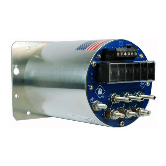
3.0 BACK PANEL & WIRING The rear views of the M651 are shown in figures 3A and 3B with the option port shown (removable terminal block at the top), which may be selected at order time, as either, the serial communication option, the 0-1mA analog transducer output option, or the 4- 20mA analog transducer output option. -
Page 25: Auxiliary Power
Figure 3B – Rear View M651 (shown with 6 position terminal block for External Split-Core CTs – Current Input Option C) 3.1 Auxiliary Power The M651 transducers are powered by connections to L1(+) and L2(-). A Green LED Power (PWR) indicator is provided on the rear panel to indicate that the unit is powered ON. -
Page 26: Specifications (Per Section 1.3)
3.2 VT Inputs – VA, VB, VC, VN (See Appendix A1 and Section 1.3) The M651 voltage (VT) signal inputs are connected to terminals 3-6 (see Appendix A1 for specific wiring configurations). Voltage signals are measured using a 12M ohm resistor divider with a continuous voltage rating of 7kV. -
Page 27: Serial Ports (See Section 4.2)
Split Core CTs. Recommended torque is 9 In-Lbs, 1.02 N-m 3.4 Serial Ports (See section 4.2) The M651 transducers are equipped with an optional serial port. The port is software (user) configurable for RS-232 or RS-485. The RS-232 drivers support full and half duplex modes. -
Page 28: Network Settings
Modbus 502 (TCP) Determining the IP Address if unknown: Bitronics has created a utility program to request the IP address for a specific MAC address on an Ethernet network. The program is available on the company website (http://www.novatechweb.com/downloads/inarp/). The program uses the Inverse Address Recognition Protocol to perform the lookup and thus is called inarp. -
Page 29: Indicators - Ethernet (Act) & Serial Leds
-v -i 192.168.1.1 00:D0:4F:03:00:15 The inarp utility is Copyright (c) 2011 by Bitronics, LLC. All rights reserved. Portions of inarp are Copyright (c) 1999 - 2005 NetGroup, Politecnico di Torino (Italy), and Copyright (c) 2005 - 2010 CACE Technologies, Davis (California). -
Page 30: Firmware Upgrades And Saving And Loading Configuration Files - Ethernet Service Port
In cases such as this, it is desirable to support a mechanism for new firmware to be installed remotely. The ability to upgrade Firmware is done over the Ethernet port. The M651 family utilizes a page in the Web Server interface to upload and install new firmware. - Page 31 “temporary internet files”, “cache” or “website data” and uncheck any boxes that preserve data. If you had a previously saved configuration that you wish to now load to your M651, you should now go back to the Load/Store Settings page and go to the top box “Select a configuration file”.
-
Page 32: Operation
(3 1/3 characters) from the time the transmitter shuts off to the next message on the bus in order to guarantee reliable communications. See figure 5 below for RS485 cable wiring diagrams. ML0039 November 14, 2013 Copyright 2013 Bitronics, LLC... - Page 33 Figure 5 - Typical RS-485 Cable Wiring ML0039 November 14, 2013 Copyright 2013 Bitronics, LLC...
- Page 34 Figure 6 – RS-232 Cable Wiring Diagram ML0039 November 14, 2013 Copyright 2013 Bitronics, LLC...
-
Page 35: Functional Description
The M651 incorporates an internet-compatible HTML web page. 5.3 Passwords Passwords can be setup in the M651 for use in controlling access to configuration and other functions. Passwords may be comprised of the 95 printable ASCII characters as defined by http://en.wikipedia.org/wiki/ASCII#ASCII_printable_characters... - Page 36 Setting up the serial ports is accomplished by using the web interface or front buttons. AOC units will only function with the M651 configured for Optimal Resolution and the Bitronics Legacy register set. When using AOCs that communicate via Modbus (NAO8101 and NAO8102), the M651 serial port must be set for an RxD to TxD Delay of 10ms for proper operation.
-
Page 37: Performing Set-Up Through The Web
3.5.1 (Network settings) to change your network configuration settings. Enter the M651’s IP address into your internet browser to connect with the M651 web page interface. Internet browsers supported are Firefox, Internet Explorer, Safari and Google Chrome. - Page 38 Data page: Two views – Instantaneous and Demands ML0039 November 14, 2013 Copyright 2013 Bitronics, LLC...
- Page 39 Settings page: Click on one of the settings categories (Identity, Input, Network, Serial Port, Protocol, Load/Store Settings, Password Security, or Firmware Upload) to be taken to the next page. ML0039 November 14, 2013 Copyright 2013 Bitronics, LLC...
- Page 40 Contact Page: ML0039 November 14, 2013 Copyright 2013 Bitronics, LLC...
- Page 41 From the Settings page screen you can select one of the following selections: Identity– This page allows the user to enter information that is necessary to identify the meter. It gives an identity to a particular M651. Each M651 should have different information entered for its identity.
- Page 42 Identity: ML0039 November 14, 2013 Copyright 2013 Bitronics, LLC...
- Page 43 Input: ML0039 November 14, 2013 Copyright 2013 Bitronics, LLC...
- Page 44 Network: Serial Port (if option ordered): ML0039 November 14, 2013 Copyright 2013 Bitronics, LLC...
- Page 45 Appendix of the respective protocol manuals. There are both fixed and configurable register/point lists. Please refer to the appropriate protocol manual for more information regarding how to view or edit the register/point list. ML0039 November 14, 2013 Copyright 2013 Bitronics, LLC...
- Page 46 Modbus DNP3 ML0039 November 14, 2013 Copyright 2013 Bitronics, LLC...
- Page 47 DNP Serial DNP TCP ML0039 November 14, 2013 Copyright 2013 Bitronics, LLC...
- Page 48 Modbus RTU Modbus TCP ML0039 November 14, 2013 Copyright 2013 Bitronics, LLC...
- Page 49 Load/Store Device Settings: Password Security Settings: ML0039 November 14, 2013 Copyright 2013 Bitronics, LLC...
- Page 50 Firmware Upload: ML0039 November 14, 2013 Copyright 2013 Bitronics, LLC...
-
Page 51: Measurements
Potential Transformer (VT) turns ratios. The VT and CT values are factory set to 1:1 CT and 1:1 VT. These values can be entered into the M651 over the network or via web page, and will be stored in internal non-volatile memory. All measurements are presented in primary units, based on these ratios. -
Page 52: Voltage Channels
On 2½ element systems, one of the phase-to-neutral voltages is missing, and the M651 must create it from the vector sum of the other two phase-to-neutral voltages. In order to configure the M651 for 2½ element mode and which phase voltage is missing, select one of the following: 2.5 element - A, 2.5 element - B, or 2.5 element –... -
Page 53: Geometric Va Calculations
For example, on a system with a lagging load on one phase and an equal leading load on another phase, the Geometric VA result will be reduced relative to a balanced system but the Total Power Factor will still be "1". ML0039 November 14, 2013 Copyright 2013 Bitronics, LLC... - Page 54 Figure 7 - Sign Conventions for Power Measurements (P is Power, Q is VARS and S is VA) ML0039 November 14, 2013 Copyright 2013 Bitronics, LLC...
-
Page 55: Compensated Watts And Vars (Line And Transformer Loss Compensation)
System losses (E) are a fixed percentage, mutually agreed upon between two electric utilities, about an interchange point that lies on a branched line. As such, E is not a physical property of any particular line, transformer or the meter, so no further ML0039 November 14, 2013 Copyright 2013 Bitronics, LLC... -
Page 56: Energy
Total Watts, Total VARs, and Total VAs, and the values are stored into non-volatile memory every 15 seconds. Energy values may be reset. All values are reset simultaneously. Refer to the appropriate protocol manual for details. ML0039 November 14, 2013 Copyright 2013 Bitronics, LLC... -
Page 57: Frequency
6.9 Frequency The M651 monitors the change in Phase Angle per unit time using the Phase Angle measurement for the fundamental generated by the FFT. The System Frequency is the frequency of the input used for synchronizing the sampling rate. -
Page 58: Ampere And Fundamental Ampere Demand
Total VA calculation type (Section 6.6) Upon power-up, all Present Total Watt, VAR, and VA Demands are reset to the average of the stored Maximum and Minimum values. The Maximum and Minimum ML0039 November 14, 2013 Copyright 2013 Bitronics, LLC... -
Page 59: Demand Resets
6.10.5 Demand Interval The M651 uses 900 seconds (15 minutes) as the default demand interval for current. The default for average volts and average power measurements is 60 seconds. Three separate, independent demand intervals may be set for current, voltage, and power. -
Page 60: Fundamental Current
TDD for the 1 Amp load and 30% TDD for the 100 Amp load (if the Denominator was set at 100 Amps). In the M651, Current Demand Distortion is implemented using Equation 3. The TDD equation is similar to Harmonic Distortion (Equation 2), except that the denominator in the equation is a user-defined number. -
Page 61: Fundamental Voltage
RMS magnitude of the selected harmonic. 6.11.4 Fundamental Voltage Fundamental Volts are the nominal component (50/60Hz) of the waveform. The M651 measures the magnitude of the fundamental phase-to-neutral and phase-to-phase volts. These measurements can be used in conjunction with the distortion measurements to obtain the magnitudes of harmonics, in other words, convert from percent to volts. -
Page 62: Phase Angles
The table below provides a reference of error codes. The Health Check value shown in the M651 web live data page is a hexadecimal representation of the binary value. For example, a Health Check value of 0000 0014 is the equivalent of the binary value 000000000010100. -
Page 63: List Of Available Measurements & Settings
6.13 List of Available Measurements & Settings Please note that not all measurements are available in every M651 model (demand and harmonic values only in M3). Available Measurements Amps A, B, C, Residual K-factor Amps A Average Volts AN, BN, CN, AB, BC, CA K-factor Amps B Average (Max.) Volts AN, BN, CN, AB, BC,... -
Page 64: Instantaneous Measurement Principles
6.15 Instantaneous Measurement Principles The M651 measures all signals at an effective rate of 64 samples/cycle, accommodating fundamental signal frequencies from 45 to 65Hz depending on model. Samples of all bus signals are taken using a 16-Bit A/D converter, effectively creating 64 "snapshots"... -
Page 65: Analog Transducer Output Option
7.3 Connections The connections for the 0-1 mA output option are shown in figure 8 while the connections for the 4-20 mA with external and internal loop are shown in figure 9. ML0039 November 14, 2013 Copyright 2013 Bitronics, LLC... - Page 66 Figure 8 – 0-1mA Transducer Output Connections ML0039 November 14, 2013 Copyright 2013 Bitronics, LLC...
- Page 67 Figure 9 – 4-20mA Transducer Output Connections ML0039 November 14, 2013 Copyright 2013 Bitronics, LLC...
-
Page 68: Appendix
HI and LO terminals for each CT input, that is, swapping 7 and 10, 8 and 11, 9 and 12. The effect is a 180 degree phase shift in the current signals. ML0039 November 14, 2013 Copyright 2013 Bitronics, LLC... - Page 69 Figure 10 - Signal Connections – M651 ML0039 November 14, 2013 Copyright 2013 Bitronics, LLC...
- Page 70 Figure 10 - Signal Connections – M651 ML0039 November 14, 2013 Copyright 2013 Bitronics, LLC...
- Page 71 Figure 11 - 50 Series External Split-Core Signal Connections ML0039 November 14, 2013 Copyright 2013 Bitronics, LLC...
- Page 72 ML0039 November 14, 2013 Copyright 2013 Bitronics, LLC...
-
Page 73: A2 Ethernet Troubleshooting
Some hubs/switches will not output an optical idle unless they receive an optical idle. This then inhibits the converter from outputting a copper link pulse enabling the M651 to link. In this condition, no device completes the link. - Page 74 ML0039 November 14, 2013 Copyright 2013 Bitronics, LLC...
- Page 75 ML0039 November 14, 2013 Copyright 2013 Bitronics, LLC...
- Page 76 ML0039 November 14, 2013 Copyright 2013 Bitronics, LLC...
- Page 77 ML0039 November 14, 2013 Copyright 2013 Bitronics, LLC...
- Page 78 CE certification and standards met. 6/14/13 Added support for loss compensation; E. DeMicco updated information on firmware upgrade 11/14/13 Updated sections 1.3 – 1.5 for UL E. DeMicco 61010 3 edition changes ML0039 November 14, 2013 Copyright 2013 Bitronics, LLC...
- Page 79 ML0039 November 14, 2013 Copyright 2013 Bitronics, LLC...
- Page 80 Bitronics, LLC 261 Brodhead Road, Bethlehem, PA. 18017 (610) 997-5100 Fax (610) 997-5450 www.novatechweb.com /bitronics...
Need help?
Do you have a question about the M651 and is the answer not in the manual?
Questions and answers