Table of Contents
Advertisement
Advertisement
Table of Contents
Troubleshooting

Related Manuals for Transtech SDG 200


Summary of Contents for Transtech SDG 200
- Page 1 Soil Density Gauge Operator’s Handbook...
-
Page 2: Table Of Contents
Table of Contents Introduction Measurement Technology Application Summary Safety Operating Requirements Controls & Components Contents Gauge Features External Controls Power Save/Auto Shut Down Part 1: Setting up the SDG Installing/Charging the Battery Start Software Main Menu Local Time and Change Date Format Setup GPS Control Menu Select Measurement Units... -
Page 3: Introduction
The density, or compaction level, is measured by the response of the SDG 200’s electrical sensing field to changes in electrical impedance of the material matrix. Since the dielectric constant of air is much lower than that of the other soil constituents, as density/compaction increases, the combined dielectric constant increases because the percentage of air in the soil matrix decreases. -
Page 4: Application Summary
Application Summary The SDG 200 is intended primarily for making density measurements on a standard 12 inch lift of soil during or after compaction. It is designed to measure coarse and fine grained materials common in standard soils used in civil construction projects. After configuring the gauge with soil properties from a standard particle size distribution report (ASTM D422) and Proctor test (ASTM D698 and D1557) the gauge will provide reliable and consistent measurements. -
Page 5: Controls & Components
Controls and Components Contents The SDG200 is packaged and shipped with the following components. Contact TransTech Systems Inc. Customer Service if any of the parts are missing. • SDG200 unit • Storage/shipping case • Operators Quickstart Guide • SDG handle •... -
Page 6: Gauge Features
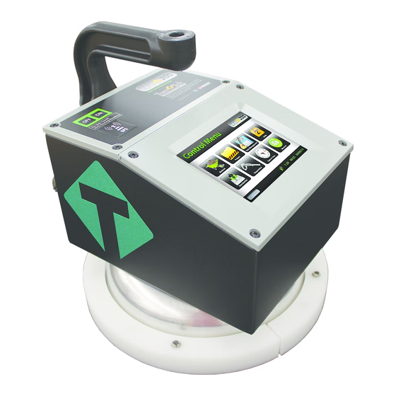
Gauge Features Handle On\Off Button Used to carry the gauge Turns gauge on and off Handle Extension GPS Module Used to connect handle Location of GPS extension unit on the gauge (Accurate to 5+- Meters) TouchScreen Used to input and interact with the gauge Faceplate... -
Page 7: External Controls
External/Internal Controls External controls on the SDG 200 consist of an ON/ OFF switch and 480x640 VGA touch screen display for navigating through the user interface and entering alpha/numeric data. Be sure not to drag your finger from one button to the next. -
Page 8: Power Save/Auto Shut Down
Setting up the SDG 200 Prior to using the SDG 200 for the first time the gauge will need to be configured to make measurements and record data correctly. The following steps must be completed before operating the SDG 200: 1. -
Page 9: Installing/Charging The Battery
Installing/Charging the Batteries You will find a plate on the back of the SDG 200 with 4 spring loaded bolts. • Turn each bolt approx. 2 full turns until the spring releases • Remove the plate from the gauge • Next you will find a wire with a connector, disconnect the battery from the gauge •... -
Page 10: Start Software
It is important to re-charge the battery after each use. Starting the Software Turn the SDG 200 on by pressing the ON button. After a few seconds the TransTech splash screen will appear followed by the Main Menu Screen. The Main Menu screen will display six options. Start SDG200,... -
Page 11: Main Menu
The Update Software button will The GPS Control button when pressed will open a screen be used in the event that TransTech which will allow you to enable releases an update to the software or disable the GPS. -
Page 12: Local Time And Change Date Format
Local Time and Change Date Format To set the time, Press Set Time. Press the appropriate numbers for the time in 24 hour format. Once you are satisfied with your entry, Press Accept to store and return to the previous screen. To set the date, Press Set Date. -
Page 13: Setup Gps
Setup the GPS Setting up the GPS is nothing more than turning it on and waiting to connect to satellites. It can take up to 15 minutes to connect to satellites depending on your location. From the Main Menu, Press GPS CONTROL. GPS status can be toggled ON or OFF. -
Page 14: Control Menu
Control Menu From the Main Menu Press Start SDG 200 to obtain the Control Menu. From this menu, you will find the icons listed below. Starts the standardization process Opens the material details screen Opens the project details screen Opens the diagnostics screen Opens the data management screen. -
Page 15: Select Measurement Units
The SDG 200 is configured to store 10 unique projects that are identified by user entered descriptions. If 10 projects have been defined in the SDG 200 and an 11th project is required, one of the original 10 will need to be modified to reflect the new project. - Page 16 Project Details The default Projects stored in a new SDG 200 will have generic Project names (i.e. Project1, Project2, etc) along with generic Project details (i.e. My Street, My Road, Contact). Project Detail screens will resemble the Material Detail screen such that you are able to select your Project using the up and down arrows.
-
Page 17: Define, Edit Or Upload Material Properties
Proctor Test and Gradation Report for the soil being tested are input accurately into the gauge. The SDG 200 is configured to store 20 unique materials that are identified by user entered descriptions. If 20 materials have been defined in the SDG 200 and a 21 material is required, one of the original 20 will need to be modified to reflect the material properties of the new material. -
Page 18: Define And Editing A Material
Define, Edit or Upload Material Properties Note: Be sure that the units of the gauge are set for the same units as the material you are uploading. If, for example, the gauge was set in U.S. Customary units (ex: 150 lb/ft3) and you were to upload the material in SI units (2402.8 kg/m3) the gauge will notify you that the density is out of range. - Page 19 Defining and Editing a Material From the Control Menu, Press Material for the Material Details screen. The material highlighted in green on the left is displayed in detail on the right. To edit the details of this material, Press Edit Material. There are fifteen material properties for each material.
-
Page 20: Setting Measurement Offsets
Setting Measurement Offsets The SDG 200 has been designed to determine the moisture and density in a compacted soil sample without the need for any offsets. The ability to measure moisture and density is based on an empirical model that was developed by studying common soil types at near optimum moisture contents with typical particle size distributions. - Page 21 Setting Measurement Offsets Offsets for Wet Density and % Moisture can be set manually by the operator in cases where the SDG 200 does not appear to be comparing favorably to collocated measurements. The offsets are simply added to or subtracted from the Wet Density and % Moisture calculated by the SDG 200. Dry Density, Volumetric Moisture, and % Compaction are then recalculated based on the offset values of Wet Density and % Moisture.
-
Page 22: Determining Offset Values
SDG 200 offset will be negative. At a particular location, if you are not able to get repeatable measurements with either the SDG 200 or your reference equipment, there may be an anomaly in the soil that effects the equipment and a new location should be selected. -
Page 23: Upload Material
Uploading a Material The file name of the materials located on the USB drive will appear on the left and some details identifying that specific material will be displayed on the right. Use the up or down arrows to highlight the material you wish to upload. -
Page 24: Part 2: Running A Test
Surface Preparation While the SDG 200 unit stands off from the soil, surface condition is still important. It is necessary for the soil surface to be free from any loose and disturbed material, stones, large air pockets or ‘divots’ and other debris. -
Page 25: Measure Density
Measure Density Turn the SDG 200 on by pressing the ON button. After a few seconds the TransTech splash screen will appear followed by the Main Menu screen. The Main Menu screen will display six options. Start SDG200 Internet (Coming Soon) - Page 26 Measure Density Press Project to verify the Project Name that the data will store under as well as the Project Details. Once verified, Press Control Menu from the status bar. Press Measure, to enter into the Soil Reading screen. In the bottom left corner, the name of the material to be tested and project are displayed for verification as well as the temperature of the soil.
- Page 27 Measure Density Position the gauge on the material in position 1 as it appears on the screen. Do not touch the gauge while it is busy taking a measurement. When reading 1 is complete, the green 2 will be illuminated. Move the gauge to position two and press 2.
-
Page 28: Select A Different Material To Test
Select a Different Material to Test At any time you wish to go back and change the Material to be tested you may do so. From the Control Menu, Press Material. By using the up or down arrows you can change the material, return to the Soil Reading screen and begin testing. -
Page 29: Part 3: Data Storage And Downloading Data
Part 3: Data Storage and Downloading Data The SDG 200 saves two types of data files. One file contains information that is referred to as diagnostic data, the other file contains information that is referred to as measurement data. Data files can be removed from the SDG 200 via a USB flash drive. -
Page 30: Storage Capacity
Storage Capacity The SDG 200 has the capability to store up to twenty detailed projects and twenty detailed materials with an overall storage capacity of over 1000 MB for all data files. Upon completion of a set of five measurements, the complete details of the test will be written to a file and saved on the instrument ONLY AFTER THE ACCEPT BUTTON HAS BEEN PRESSED. -
Page 31: Part 4: Maintenance And Troubleshooting
Keep SDG bottom surface clean: For accurate readings, the SDG 200 should have a smooth interface with the surface. Try not to place the SDG 200 on top of large rocks that would cause the gauge not to sit properly. Also, do not try to “dig” the gauge into the material. -
Page 32: Troubleshooting
Maintenance The Diagnostic button on the Control Menu will turn red as a reminder. Only authorized distributors or the factory are able to perform this type of calibration. Troubleshooting The chart below provides guidance to a few suspect conditions. Problem Remedy Buttons Sticking/Frozen Software Repress the frozen button firmly for three seconds. -
Page 33: Troubleshooting
Troubleshooting The chart below provides guidance to a few suspect conditions. Problem Remedy Battery Problems/Gauge Keeps Shutting Ensure battery pack is plugged in Check battery voltage-plug gauge into charger and Down/Gauge Will Not Come On wait for the green LED to illuminate to indicate a full charge Call Factory Data is not recording... -
Page 34: Definition Of Material Properties
Definitions of Material Properties The following descriptions and material properties need to be entered in the gauge for measurement or data reporting purposes: Material ID: Usually a numeric entry that will associate the soil being tested with the gradation and proctor test report. -
Page 35: Part 6: Standardization Of Sdg
A metallic plate has been installed in the bottom of the SDG 200 carrying case that is suitable for this purpose. Although this verification is referred to as a standardization of the gauge, the results of the standardization in no way influence the measurement of the gauge, they only serve to alert the user to a change in the way that the gauge is operating. -
Page 36: Part 7: Explanation Of Gradation And Compaction Reports
Part 7: Explanation of Gradation and Compaction Reports All of the information needed to configure an SDG 200 to measure the density and moisture content of a material is available on Compaction Test Reports (Proctor Test) and Particle Size Distribution Reports (Gradation/Sieve Analysis) completed as outlined by ASTM D 422 and ASTM D 1557. - Page 37 Part 7: Explanation of Gradation and Compaction Reports The thirteen properties that will need to be entered through the SDG’s user interface are shown on the Material Details screen above and defined below. Further definitions of these properties can be found in Part 5 of the SDG Operators Handbook.
- Page 38 Part 7: Explanation of Gradation and Compaction Reports % Greater than 3 inches is the percentage of the sample that is retained on the 3 inch sieve. Typical gradation tests report the “percent finer” or percentage that passes a particular sieve. In this example the percent finer for the 3 inch sieve is 100% so 0% of the sample is retained on the 3 inch sieve.
- Page 39 Part 7: Explanation of Gradation and Compaction Reports !! Note: The sum of %Greater the 3 inches, %Gravel, %Sand, and %Fines must add up to 100%. The default values programmed in the SDG software add up to 100%. As soon as one of those values is edited, the sum will no longer add up to 100% and an error message will be displayed until all of those gradation values are entered such that the sum is 100% again.!!
- Page 40 Appendix A: Using the SDG MTL Generator The SDG MTL Generator is a spreadsheet based application developed to determine the gradation inputs that the SDG needs to measure moisture and density of a soil in cases when the gradation performed was not done in accordance with ASTM D 422.
- Page 41 Appendix A: Using the SDG MTL Generator Screen One: Screen Two: The second screen of the MTL displays the plot of the particle size distribution curve and displays a table of all of the material properties that will be converted into a text file to upload to the SDG. On Screen 1, input the sieves used in the gradation (in mm) and the percent of material passing each sieve in columns A and B.
- Page 42 Appendix A: Using the SDG MTL Generator Screen Two: Once the gradation data is entered, fill in the rest of the material definition information in the yellow cells on Screen 1. The explanations and limitations for those definitions are explained on Screen 1. Clicking on the button to view the Particle size distribution curve displays Screen 2.
- Page 43 Appendix A: Using the SDG MTL File Tool The MTL File Tool is designed to allow users to easily create .mtl files to upload into the SDG. If a gradation report completed in accordance with ASTM D 422 is available, all of the information on that report can be entered into the table on the Gradation file tool and a .mtl file will automatically be generated and saved to the Desktop of your PC.
-
Page 44: Sdg Unit Warranty
Unused products will be issued a credit to the Purchaser’s account that was used to purchase the product. TransTech will not credit prepaid shipping cost. The original packing slip or invoice is required to be sent back with the product to be returned. - Page 45 Notes:...
- Page 46 Notes:...
- Page 47 Notes:...
- Page 48 ����������������� ��������������������� ������������������������� ����������������� ��������������������������������� ������������������������� ����������������������������������� ������������...
Need help?
Do you have a question about the SDG 200 and is the answer not in the manual?
Questions and answers