Advertisement
Quick Links
EN
INSTALLATION AND OPERATING MANUAL
Global Water Solutions Ltd.
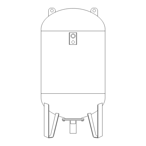
SuperFlow™ Series
Installed on __________ by ________________
PLEASE READ ALL INSTRUCTIONS BEFORE INSTALLING YOUR NEW
GLOBAL WATER SOLUTIONS (GWS) TANK
CAUTIONS AND WARNINGS
⚠ CAUTION: To prevent personal injury, ensure all water pressure is released from the pressure system
prior to work being performed. Ensure pumps are disconnected and/or electrically isolated.
⚠ WARNING: It is strongly recommended that the system is protected by a suitable pressure relief
valve set at or below the maximum tank pressure rating. Failure to install a relief valve may result
in tank explosion in the event of a system malfunction or over pressurization, resulting in property
damage, serious personal injury or death.
⚠ WARNING: If the pressure tank leaks or shows signs of corrosion or damage do not use it.
⚠ WARNING: If the expansion tank is heavier than 30 kgs, proper equipment such as lifting crane etc.
should be used in order to avoid damage to the tank and personnel.
These instructions have been prepared to acquaint you with the correct method of installing and
operating your GWS pressure tank. We urge you to study this document carefully and follow all of
the recommendations. In the event of installation difficulties or the need for further advice, you should
contact the dealer from whom you purchased the system or the nearest GWS sales office.
• SuperFlow™ Series tanks are designed for use in well water, potable water booster systems (Refer to
Sec. 1 for installation details) and for use in non-potable closed loop hydronic or solar water heating
systems (Refer to Sec. 2 for installation details) as well as for use in open loop potable water heating
applications. (Refer to Sec. 2 for installation details.)
• See tank data label for maximum working pressure and maximum temperature.
• Be sure to protect tank, piping and all system components from freezing temperatures.
• The manufacturer is not responsible for any water damage in connection with this pressure tank.
INSTALLATION MUST BE IN ACCORDANCE WITH LOCAL AND STATE PLUMBING CODES.
www.globalwatersolutions.com
1. Well Water and Booster System Tank Installation
1.1 Proper GWS Tank Location
In order to ensure your tank provides its maximum service life it should always be installed in a covered,
dry position. The tank should not be allowed to rub against any surrounding hard surfaces, such as walls
etc.
1.2 System Connection
1. Place the GWS tank in its final desired location.
2. Level as necessary. All vertical and horizontal model tanks should be placed on a firm base. If vibration
is likely to occur in the vicinity the tank should be mounted on a resilient mounting.
3. Connect the tank to the pump supply line with a short pipe to eliminate unnecessary friction loss.
4. All piping should be in accordance with prevailing local codes and standards.
5. Tanks mounted on booster sets should be strapped down for shipment.
1.3 Adjusting Precharge Pressure
Correct precharge is required for proper tank performance.
1. For tanks installed with a pressure switch controlled pump with a differential pressure set up to 2 bar
(30 psi), the precharge should be set to 0.2 bar (2 psi) below the cut-in pressure.
2. For tanks installed with a pump controlled by a pressure switch with a pressure differential greater
than 2 bar (30 psi), electronic controls or variable speed controls, the precharge should be set to 65%
of the cut-out or maximum system pressure.
3. For tanks installed on mains' pressure, the tank precharge should be set equal to the mains' pressure.
For mains' pressure exceeding 6 bar (88 psi), a suitable pressure regulator should be installed.
4. Precharge of SuperFlow™ tanks should be checked every 3 months.
For correct operation, pressure tanks should be precharged as follows:
1. Turn off the pump, disconnect the tank from the system and completely drain all water inside the tank
to avoid water pressure affecting precharge readings.
2. Using a suitable pressure gauge, check the precharge pressure of the tank.
3. Release or add air as necessary to adjust to the required precharge pressure.
4. Replace protective air valve cap and seal with the air valve label, if provided. This will enable you to
determine if the valve has been tampered with in case of future service calls.
⚠ CAUTION: Never over-charge the tank and precharge the tank with air at ambient temperature only!
If the tank is to be precharged over 4 bar (58 psi):
Revision: M-BT1-1.07
1. Adjust the precharge of the tank to 4 bar (58 psi).
2. Install the tank into the system.
3. Fill the system with water to equalise the system and precharge pressure at 4 bar (58 psi).
4. Increase precharge pressure in maximum 3 bar (44 psi) steps and afterwards adjust the system
pressure to the new precharge pressure by filling water into the system.
5. Repeat steps 3 and 4 until the required precharge is reached.
Emptying a tank that has a precharge over 4 bar (58 psi):
1. Make sure there is some water in the tank.
2. Isolate the tank from the system (close isolation valve).
3. Make sure no additional water can get into the tank (shut off the pump and/or any water supply).
4. Release air from tank until 3 bar (44 psi) tank/air pressure is remaining.
5. Open a drain valve and afterwards the isolation valve to drain the tank.
⚠ CAUTION: Make sure that the system pressure is never lower than 4 bar (58 psi) below precharge. If
system pressure needs to be lowered, the tank should be isolated or emptied as previously described.
1.4 Pump Run Control Operating Principles
Without a pressure tank, a water system's pump would cycle (turn on) every time there was a demand
for water. This frequent and potentially short cycling would shorten the life of the pump. Pressure tanks
are designed to store water when the pump is running and then deliver pressurized water back to the
system when the pump is shut off (Fig 1.4). A properly sized tank will store at least one liter of water for
every liter per minute (LPM) of pump capacity. This allows for fewer pump starts and longer run times
which should maximize the life of the pump.
1. Before drawdown
2. During
3. Pump comes on
drawdown
and begins to fill
the tank
Fig. 1.4
1.5 Multiple Tank Installation
All tanks must have the same precharge for the system to function properly. Tanks should be installed on
a header to ensure all tanks receive equal and balanced pressure. Adjust each tank precharge as detailed
in section 1.3. The system pressure switch or control should be centrally located (see Fig 1.5) in order
for the tanks to function properly.
NOTE: All tanks must have
equal precharge
Relief
Pressure
Valve
Switch
Header to be sized
for maximum velocity of
1.8m/sec (6ft/sec)
Fig. 1.5 Multi-tank Installation
2. Thermal Expansion Tank Installation
Thermal expansion tanks are designed to accommodate the natural expansion of water as it is heated.
Thermal expansion tanks may be used in several different applications including closed loop hydronic
heating systems, direct and indirect solar heating systems, and open loop potable water heating systems.
GWS has developed three different series of tanks to be used for each application: HeatWave™ for
closed loop hydronic heating systems, SolarWave™ for indirect closed loop solar heating systems, and
ThermoWave™ for direct solar heating and open loop potable water heating systems. For high volume
thermal expansion applications Challenger™ and SuperFlow™ Series tanks may be used.
⚠ CAUTION: Check tank data label for maximum operating pressure and temperature prior to
installing.
⚠ CAUTION: Additives (such as glycol) can affect the thermal expansion and expansion tank operation.
Check with your GWS dealer or nearest GWS sales office for more details.
2.1 Precharge
Using a suitable pressure gauge, check the tank precharge pressure prior to installation. Refer to the tank
data label for factory precharge pressure. Tanks in closed loop heating circuits should be precharged to
system fill pressure. Tanks in open loop heating storage systems should be precharged to mains' pressure.
For tanks in closed loop solar systems precharge should be set at minimum system operating pressure
and/or fill pressure. Release or add air by the tank air valve accordingly. Make sure the tank is completely
drained of water and there is no system pressure affecting the precharge pressure reading when adjusting
tank precharge.
2.2 Thermal Expansion Tank Location
As tanks, pipes and connections can leak even when installed correctly; make sure to install the tank at
a location where any leak will not cause water damage. The thermal expansion tank should be installed
on the cold or supply side of any heating system. The tank should be installed indoors and protected
from freezing temperatures.
2.3 System Connection
SuperFlow™ tanks are designed to be self-supporting and should be connected to the system with
additional piping (See Fig. 2.3).
Hot
Cold
BackFlow Preventer or
Check Valve
Relief
Valve
Vertical
Tank
w/ Feet
Fig. 2.3
Advertisement

Related Manuals for Global Water SuperFlow SFB-750LV

Summary of Contents for Global Water SuperFlow SFB-750LV
- Page 1 ⚠ CAUTION: Never over-charge the tank and precharge the tank with air at ambient temperature only! GLOBAL WATER SOLUTIONS (GWS) TANK ⚠ CAUTION: Additives (such as glycol) can affect the thermal expansion and expansion tank operation. Check with your GWS dealer or nearest GWS sales office for more details.
-
Page 2: Declaration Of Conformity
MBPA-16 8-10000 II, III, IV EN13831:2007 4. Membrane Replacement Instructions Global Water Solutions Ltd. (GWS) warrants its SuperFlow™ tanks for a period of 1 years from the MBPA-25 8-10000 II, III, IV EN13831:2007 date of manufacture for manufacturing defects on the steel shell. Warranty applies to GWS products...