Table of Contents
Advertisement
Quick Links
Qubino
The INNOVATIVE and SMALLEST
Weather Station
ORDERING CODE
Z-WAVE FREQUENCY
ZMNHZD1
868,4 MHz
ZMNHZD2
921,4 MHz
ZMNHZD3
908,4 MHz
ZMNHZD4
869,0 MHz
ZMNHZD5
916,0 MHz
ZMNHZD8
865,2 MHz
Weather Station is used for measuring temperature,
humidity, wind & rain properties and sending the
measurement values to your Z-Wave network.
The Weather Station can measure 10 different values: two
sets of temperature/humidity sensors, wing gauge with 5
sensors (direction, velocity, wind gust, temperature and
wind chill) and a rain sensor. With the use of the included
Weather Station USB KEY all 10 values (end points) are
sent and rendered in your home Z-Wave network.
Qubino Weather Station Key is used for receiving Wireless
data packages (from Thermo/ Hygro Sensor Ch1, Thermo/
Hygro Sensor Ch2, Rain Gauge, Wind Gauge) and sends
it to the Z-Wave Controller.
The Key is designed to be plugged into the USB Power
Adapter. Module receives data for Temperature, Wind
Chill, Velocity, Wind Gust, Wind Direction, Humidity, Rain
Rate and Battery Level for each Sensor.
It is designed to act as repeater in order to improve range
.
and stability of Z-wave network
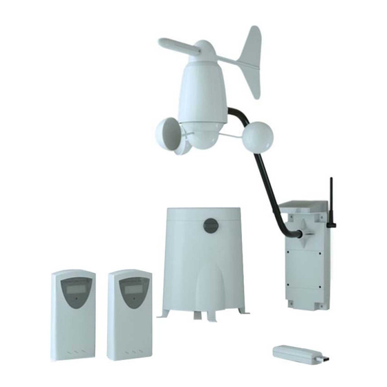
Package contents:
Weather Station USB Key
2 x Thermo-Hygro Sensor
Anemometer (Wind Sensor with Solar panel)
- Wind cups
- Wind vane
- Anemometer arm
- Anemometer base
- 4 screws
Rain Sensor
- Funnel shaped lid with battery hatch
- Sensor base
- Bucket see-saw mechanism
- Protective screen
-
4 screws
Weather Station USB Key
Installation
Connect the Weather Station Key into the USB
Power Supply.
Locate the module far from metal elements.
Locate the module in the range of Z-Wave Network
and in the range of all 433 MHz sensors.
S
Service button (used to add or remove module
from the Z-Wave network).
L
LED
LED Blinking Meaning
LED is 1 second ON and 1 second OFF
The module is in exclusion mode
LED is ON
The module is in inclusion mode
LED Blinks 1 time fast
The module received data from Thermo/Hygro Sensor Ch1
LED Blinks 2 time fast
The module received data from Thermo/Hygro Sensor Ch2
LED Blinks 3 time fast
The module received data from Wind Sensor
LED Blinks 4 time fast
The module received data from Rain Sensor
Module
Inclusion (Adding to Z-Wave
network)
Connect module to USB Power Supply
auto-inclusion (works for about 5 seconds after
connected to power supply) or
enable add/remove mode on main controller
hold service button S between 1.5 and 4 seconds
NOTE: For auto-inclusion procedure, first set main
controller into inclusion mode and then connect module to
USB power supply.
Module Exclusion/Reset (Removing from
Z-Wave network)
Connect module to power supply
enable add/remove mode on main controller,
hold service button S between 4 seconds and 8
seconds
By this function, all parameters of the module are set to
default values, own ID is deleted and the module will
include as unsecure next time.
If service button S hold more than 1.5 and less than 4
seconds module is excluded, but configuration parameters
are not set to default values and the module will include
next time as it was set into the Configuration Parameter
250.
Association
Association enables Weather Station module to transfer
commands inside Z-Wave network directly (without main
controller) to other Z-Wave modules.
Associated Groups:
Group 1: Lifeline group (reserved for communication with
the main controller), one node allowed.
Group 2: basic on/off (triggered when the Wind Gust of the
Wind Gauge exceed the Configuration Parameter 1 Value)
up to 16 nodes.
Group 3: basic on/off (triggered when the Rain rate exceed
the Configuration Parameter 2 Value) up to 16 nodes.
Endpoint 1: Thermo/ Hygro Sensor Ch1 – Temperature
Group 1: Lifeline group, 0 nodes allowed.
Endpoint 1 receives Temperature data from Thermo/
Hygro Sensor on Channel 1. It is capable of receiving data
in range of -199.0 °C and 199.0 °C. However, the
operating temperature of the 433 MHz sensor is from -10
°C to 60 °C.
Endpoint 2: Wind Gauge – Direction
Group 1: Lifeline group, 0 nodes allowed.
Endpoint 2 receives Direction data from Wind Gauge. The
data is in range of 0.0° to 360.0°.
Endpoint 3: Wind Gauge – Velocity
Group 1: Lifeline group, 0 nodes allowed.
Endpoint 3 receives wind speed data from Wind Gauge. It
is capable of receiving data in range of 0.00 m/s to 88.00
m/s.
End point 4: Wind Gauge – Wind gust
Group 1: Lifeline group, 0 nodes allowed.
Group 2: basic on/off (triggered when the Velocity exceed
the Value of Configuration Parameter 1) up to 16 nodes.
Endpoint 4 receives wind speed data from Wind Gauge. It
is capable of receiving data in range of 0.00 m/s to 88.00
m/s.
End point 5: Wind Gauge – Temperature
Group 1: Lifeline group, 0 nodes allowed.
Endpoint 5 receives Temperature data from Wind Gauge.
It is capable of receiving data in range of -199.0 °C and
199.0 °C. However, the operating temperature of the
sensor is from -10 °C to 60 °C.
End point 6: Wind Gauge – Wind Chill
Group 1: Lifeline group, 0 nodes allowed.
Endpoint 6 receives Temperature data from Wind Gauge.
It is capable of receiving data in range of -199.0 °C and
199.0 °C. However, the operating temperature of the
sensor is from -10 °C to 60 °C.
End point 7: Rain Sensor
Group 1: Lifeline group, 0 nodes allowed.
Group 2: basic on/off (triggered when the Rain rate exceed
the Configuration Parameter Value 2) up to 16 nodes.
Endpoint 7 receives and calculates rain rate. The rain rate
is in range of 0.00 mm/h and 300.00 mm/h.
End point 8: Thermo/ Hygro Sensor Ch1 – Humidity
Group 1: Lifeline group, 0 nodes allowed.
Endpoint 8 receives Humidity data from Thermo/ Hygro
Sensor on Channel 1. The data is in range of 0% and
100%.
–
End
point
9:
Thermo/
Hygro
Sensor
Ch2
Temperature
Group 1: Lifeline group, 0 nodes allowed.
Endpoint 9 receives Temperature data from Thermo/
Hygro Sensor on Channel 2. It is capable of receiving data
in range of -199.0 °C and 199.0 °C. However, the
operating temperature of the sensor is from -10 °C to 60
°C.
End point 10: Thermo/ Hygro Sensor Ch2 – Humidity
Group 1: Lifeline group, 0 nodes allowed.
Endpoint 10 receives Humidity data from Thermo/ Hygro
Sensor on Channel 2. The data is in range of 0% and
100%.
Configuration parameters
Parameter No. 1 – Wind Gauge, Wind Gust Top Value
Available configuration parameter (data type is 2 Byte
Dec):
default value 1000 (10,00 m/s)
0 – 8800 = value from 0.00 m/s to 88.00 m/s -
if the Wind Gust is Higher than the Parameter Value,
a device triggers an Association.
Parameter No. 2 – Rain Gauge, Rain Rate Top Value
Available configuration parameter (data type is 2 Byte
Dec):
default value 200 (2,00 mm/h)
0 – 30000 = value from 0.00 mm/h to 300.00 mm/h -
if the Sensor Rain Rate is Higher than the Parameter
Value, a device triggers an Association
Parameter No. 3 – Wind Gauge, Wind Gust
Available configuration parameter (data type is 1 Byte
Dec):
default Value 1
0 - If the Wind Gust is Higher than the Parameter No.
1 Value, then a Device sends Basic Set = 0x00.
1 - If the Wind Gust is Higher than the Parameter No.
1 Value, then a Device sends Basic Set = 0xFF.)
Parameter No. 4 – Rain Gauge, Rain Rate
Available configuration parameter (data type is 1 Byte
Dec):
default Value 1
0 - If the Rain amount is Higher than the Parameter
No. 2 Value, then a Device sends Basic Set = 0x00.
1 - If the Rain amount is Higher than the Parameter
No. 2 Value, then a Device sends Basic Set = 0xFF.)
Unsolicited Report
If you enable Unsolicited Reports on the End Points, the
USB Key will send data to the controller every time it
receives data from the 433MHz sensors, which are
different from the precious data.
Parameter No. 5 – End point 1 – Unsolicited Report
Available configuration parameter (data type is 1 Byte
Dec):
default Value 1
0 – Unsolicited Report disabled
1 – Unsolicited Report enabled
Parameter No. 6 – End point 2 – Unsolicited Report
Available configuration parameter (data type is 1 Byte
Dec):
default Value 1
0 – Unsolicited Report disabled
1 – Unsolicited Report enabled
Parameter No. 7 – End point 3 – Unsolicited Report
Available configuration parameter (data type is 1 Byte
Dec):
default Value 1
0 – Unsolicited Report disabled
1 – Unsolicited Report enabled
Parameter No. 8 – End point 4 – Unsolicited Report
Available configuration parameter (data type is 1 Byte
Dec):
default Value 1
0 – Unsolicited Report disabled
1 – Unsolicited Report enabled
Parameter No. 9 – End point 5 – Unsolicited Report
Available configuration parameter (data type is 1 Byte
Dec):
default Value 1
0 – Unsolicited Report disabled
1 – Unsolicited Report enabled
Parameter No. 10 – End point 6 – Unsolicited Report
Available configuration parameter (data type is 1 Byte
Dec):
default Value 1
0 – Unsolicited Report disabled
1 – Unsolicited Report enabled
Parameter No. 11 – End point 7 – Unsolicited Report
Available configuration parameter (data type is 1 Byte
Dec):
default Value 1
0 – Unsolicited Report disabled
1 – Unsolicited Report enabled
Parameter No. 12 – End point 8 – Unsolicited Report
Available configuration parameter (data type is 1 Byte
Dec):
default Value 1
0 – Unsolicited Report disabled
1 – Unsolicited Report enabled
Parameter No. 13 – End point 9 – Unsolicited Report
Available configuration parameter (data type is 1 Byte
Dec):
default Value 1
0 – Unsolicited Report disabled
1 – Unsolicited Report enabled
Parameter No. 14 – End point 10 – Unsolicited Report
Available configuration parameter (data type is 1 Byte
Dec):
default Value 1
0 – Unsolicited Report disabled
1 – Unsolicited Report enabled
Parameter No. 15 – Random ID Enable
Available configuration parameter (data type is 1 Byte
Dec):
default Value 0
0 – Random ID disabled
1 – Random ID enabled
If Random ID is disabled, the Weather Station USB Key
can receive data from multiple 433 MHz Sensors on the
same Channel. If the Random ID is enabled, the USB Key
can receive data from only one sensor on the same
channel. If the USB Key does not receive a data from a
sensor on a specific channel for more than 2.5 hours, it
clears the Random ID of the device and waits for a new ID.
If you replace the batteries in the modules, the Random ID
will change. If you want that the USB Key accept a module
immediately, set the Parameter No. 15 to "0" and in the
next step again to "1".
Parameter No. 250 – Unsecure / Secure Inclusion
Available configuration parameter (data type is 1 Byte
Dec):
default Value 0
0 – Unsecure Inclusion
1 – Secure Inclusion
The Weather Station Key supports both, the secure and
unsecure inclusion. Even if the controller does not support
security command classes, the Key could be included as
unsecure
and
keep
all
the
functionality.
By default, the Key includes as unsecure. To include the
Key as secure follow the procedure:
1.
Include the Key into the controller
Set the parameter 250 to the value "1"
2.
3.
Enable add/remove mode on main controller,
4.
Hold service button S between 1.5 and 4 seconds
to exclude the module
5.
If the exclusion of the module was successful, the
LED on the module starts blinking
6.
Unplug the module out of the power supply
7.
enable add/remove mode on main controller
8.
Plug the module into the power supply to star auto-
inclusion
9.
Now the module should be included as secure
The same procedure is to include the module as unsecure.
Safety Procedure
I
n the case of lost connection between the 433 MHz
Wireless Sensor and the Weather Station USB Key (more
than 15 minutes of lost connection), the module will set
Sensor values to extreme values. (Temperature =
-199.0 °C, Velocity = 88.00 m/s, Rain = 300.00 mm/h,
Humidity = 100 % or Direction = 0.0°), so that the
associations and scenarios are triggered to lower the
chance of potential damage.
If the Weather Station USB Key lose the power supply (or
any other reason reset the Key), the Key will not report
Sensor Values to the controller until new data is received
or maximum 240 seconds. If after 240 seconds, the Key
still does not have new data from the sensor, it will set the
sensor values to extreme values.
On each End point we can get battery level from
corresponding sensor. On the Root device is a battery
level from the sensor with the lowest battery level.
Technical Specifications
Weather station
Dimensions (WxHxD)
460x120x430mm
Weight
2 kg
USB Key
Advertisement
Table of Contents

Related Manuals for QUBINO ZMNHZD1

Summary of Contents for QUBINO ZMNHZD1
- Page 1 USB power supply. Group 1: Lifeline group, 0 nodes allowed. Qubino Weather Station Key is used for receiving Wireless 1 – Unsolicited Report enabled By default, the Key includes as unsecure. To include the Endpoint 8 receives Humidity data from Thermo/ Hygro Parameter No.
- Page 2 The battery statuses of the sensors are checked every shorter electronic life span, damaged battery and distorted Endpoint 1, 2, 3, 4, 5, 6, 7, 8, 9, 10 Qubino air circulation and sheltered from direct sunlight and other hour. If the low battery indicators light up, replace the parts.
Need help?
Do you have a question about the ZMNHZD1 and is the answer not in the manual?
Questions and answers