Table of Contents
Advertisement
Quick Links
5.00 OPERATING PARAMETERS
NAME
MEANING
SETTING (for PTC std)
Range between «LoS» &
SEt
Main Set Point
«HiS»
Thermostat differential
Range 0 ... 10 °C
HYS
(hysteresis)
Minimum value for SET POINT
Range –50 ... +100 °C
LoS
parameter
Maximum value for SET POINT
Range –30 ... +154 °C
HiS
parameter
Thermostat control action:
0: cold;
Act
cold/heat
1: heat.
LoA
Low temperature alarm point
Range –50 ... +100 °C
HiA
High temperature alarm point
Range –30 ... +155 °C
0: disabled;
1: enables Hit;
Alr
Alarm mode of operation
2: enables Lot;
3: enables Hit & Lot.
Probe offset. Temp. correction
Range –9.9 ... +9.9 °C
OFS
factor
dPt
Defrost pause time
Range 1 ... 254 (see "tis")
ddt
Defrost duration time
Range 0 ... 99 (see "tis")
AcY
Anticycling time
Range 0 ... 254 (see "tis")
Adi
Alarm delay on power-on
Range 0 ... 99 min
0: Celsius
unt
Measure unit
1: Fahrenheit
dio
Digital input
0 ... 2 (optional)
0: dPt [h], ddt [m], acy [s];
Time scale of defrost and
1: dPt [m], ddt [s], acy [s];
tiS
anticycling
2: dPt [h], ddt [m], acy [m];
3: dPt [m], ddt [s], acy [m];
utd
Update time delay
Range 0 ... 60 s
0: decimal;
rES
Resolution
1: unit.
Limits between «LoS» &
St2
Set point 2 (dio - energy saving)
«HiS»
6.00 ANOMALIES SIGNALING
MSG
CAUSE
OUTPUT
Lot
Measured temperature is
The relay status
lower than «LoA»
does not change.
The internal buzzer
will switch on.
HIt
Measured temperature is
The relay status
higher than «HIA»
does not change.
The internal buzzer
will switch on.
PrF
The probe input line is
The relay will switch
open or short circuited
off
ATEX reserves the right to make changes without further notice to any products herein to improve reliability, function or design. ATEX does not assume any responsibility
for any improper use or application of any product or circuit described herein. ATEX products are not designed, intended, or authorized to be use as components in
systems or applications intended to support or sustain life, or for any other application in which the failure of the ATEX product could create a situation where personal
injury or death may occur.
7.00 PARAMETER DESCRIPTION
SEt – Main Set Point: it's the required temperature.
HYS - differential hysteresis: the value that controls the
compressor/heater operation, moving the value of the set point in such a
way that the system does not oscillate.
LoS - low limit of set point: a limit below which it is not possible to
move the set point value.
HiS - high limit of set point: a limit above which it is not possible to
move the set point value.
Act - thermostat action: describes the way by which the controller
manages the controlled variable. 0: direct/cold action, good for
refrigerating units, 1: inverse/heat action, usable for boiler units.
LoA - low operation point of alarm temperature: a limit below which
the system goes in alarm and simultaneously the display shows «LoT».
HiA - high operation point of alarm temperature: a limit above which
the system goes in alarm and simultaneously the display shows «Hit».
Alr - alarm mode of operation: the high and low temperature alarms
can be enabled or disabled as required by the installer. The available
options are: 0 = all alarms disabled; 1 = only high temperature alarm
enabled; 2 = only low temperature alarm enabled; 3 = high and low
temperature alarms enabled.
OFS - offset of temperature: it is the variation temperature added or
subtracted to the temperature measured by the probe to compensate for
any deviation from the real value.
dPt - defrost pause time: it is the time between the start of two
consecutive defrost actions (time cycle).
ddt - defrost duration time: it is the duration of the defrost in each
cycle. Set ddt=0 to disable any defrost action.
AcY - anticycling delay time: it is the minimum time between two
successive maneuvers of the main relay (off – on cycle). It is also the
delay for the first activation of the relay at the start-up.
Adi - alarm delay initialization: delay between the power-up of the
instrument and the arming of the alarms if enabled.
unt – Measure unit: it switches the temperature unit between Celsius
and Fahrenheit.
dio - digital input mode operation: (optional) no active.
tiS - scale times: it switches the scale times of the dPt from hours to
minutes, ddt from minutes to seconds, acy from seconds to minutes and
vice versa.
utd – update time delay: it sets the time delay between two display
refreshes.
rES - resolution: it allows to display the measured value with decimal or
unitary resolution.
St2 – 2dary set point: No active – it is useful for the energy saving
option, combined with the dio parameter.
ATEX Industries srl
ATEX Industries srl
ATEX Industries srl
ATEX Industries srl
Z.I. Ponte Rosso - Via Forgaria, 7
33078 S. Vito al Tagliamento – PN - Italy
Tel.: +39 0434 85183 r.a.
Fax: +39 0434 85338
web: www.betaelectronics.it
e-mail: beta@betaelectronics.it
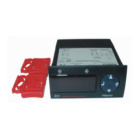
RD31
by ATEX
Rev.: 07-07-2006
Cod.: 00990226
The RED LINE SERIES
Installation and operating
instructions
Temperature controller
Advertisement
Table of Contents

Summary of Contents for BETA Electronics RD31
- Page 1 2: dPt [h], ddt [m], acy [m]; RD31 Adi - alarm delay initialization: delay between the power-up of the 3: dPt [m], ddt [s], acy [m]; instrument and the arming of the alarms if enabled.
- Page 2 -the cables of the probes and the ones of the controller supply or the loads must be separated and not close, to reduce spikes and noise on 4.50 HOW TO ACTIVATE MANUALLY A DEFROST CYCLE (only for RD31-50xx and RD31-60xx standard – not “OnOff”) the sensor.
Need help?
Do you have a question about the RD31 and is the answer not in the manual?
Questions and answers