Table of Contents
Advertisement
Advertisement
Table of Contents

Subscribe to Our Youtube Channel
Related Manuals for FläktGroup Multi-DENCO


Summary of Contents for FläktGroup Multi-DENCO
- Page 1 ® Multi-DENCO OPERATION MANUAL...
-
Page 2: Table Of Contents
Multi Table of Contents -DENCO Overview of Units and Scope of Supply ......... 13 1.1 Introduction ....................13 1.2 Model number explained ................13 1.3 Product series overview ................14 1.4 DENCO-OfficeCool .................. 15 1.5 Scope of supply ..................15 1.6 Accessories and special equipment ............ - Page 3 13.1 Pre-Commissioning Checklist (DQA 880) ..........109 13.2 Pressure Test Certificate (DQA 653) ............112 13.3 Multi-DENCO Commissioning Report (DQA 890) ........113 PROTECTION NOTICES The reproduction, distribution and utilization of this document as well as the communication of its contents to others without express authorization is prohibited.
- Page 4 The following pages demonstrate the possible type code and options for a Multi-DENCO unit. The DENCO OfficeCool short type code is listed on page 12. Please note that the type code is subject to updates and addition due to our continuous improvement process, therefore for the latest options available please contact your local office.
- Page 5 Multi-DENCO Refrigeration DENCO Multi-DENCO Refrigeration R410A Single circuit Small compressor Standard compressor Not fitted Electronic expansion valve Not fitted Shut off valves compressor and liquid line Shut off valve liquid line Solder connections Twin solder connections Refrigerant leakage detection Not fitted...
- Page 6 Multi-DENCO Water Denco Multi-DENCO Water Shut off valves chilled water Not fitted Threaded pipework connections (BSPT) Flange pipework connections PN06 Flange pipework connections PN16 Solder connections Not fitted Temperature monitoring probes Not fitted 2-way water valve 2-way water valve, pressure independent 3-way water valve with bypass 3-way water valve with bypass &...
- Page 7 Multi-DENCO CombiCool Denco Multi-DENCO CombiCool Shut off valves chilled water Not fitted BSP pipework connections Flange pipework connections PN06 Flange pipework connections PN16 Solder connections Not fitted Temperature monitoring probes Not fitted 2-way water valve 2-way water valve, pressure independent 3-way water valve 3-way water valve with bypass &...
- Page 8 Multi-DENCO Controls DENCO Multi-DENCO CO Controls C5-12 controller Not fitted LonWorks interface BACnet MS/TP interface BACnet I/P, SNMP, Webpage interface Not fitted Touch screen display Not fitted Run status unit Not fitted Water detection, sensor tape and drain pan sensor...
- Page 9 Multi-DENCO Casing DENCO Multi-DENCO Casing Pipework bottom entry Standard display position Lower display position Not fitted White Other unit colour (special) Filter differential pressure gauge Not fitted Top air discharge protection grille (Eyelash) Top air inlet protection grille (Eggcrate) Air damper...
- Page 10 Multi-DENCO Outdoor Unit * DENCO Multi-DENCO Outdoor unit Condenser R410A EC fan AC fan with fan speed controller AC fan Single circuit Not fitted 3~ 400 V, N, PE, 50 Hz 1~230 V, N, PE, 60 Hz 1~265 V, N, PE, 60 Hz...
- Page 11 Multi-DENCO Accessories DENCO Multi-DENCO Accessories Size 010 Size 018 Size 030 Size 045 Size 065 Size 092 Size 130 Base stand Plinth PLIO Plinth, other colour (special) Raised floor tile support Condensate pump Condensate pump at humidifier Shut off damper...
- Page 12 Multi-DENCO DENCO-OfficeCool Denco Multi-DENCO Chilled water OfficeCool Split System OfficeCool Size 010 Size 018 Size 030 Size 045 Downflow Upflow Front full height panel Standard heat exchanger Heat pump heat exchanger Not fitted Steam humidifier standard conductivity Steam humidifier low conductivity...
-
Page 13: Overview Of Units And Scope Of Supply
Introduction We would like to thank you for purchasing our products. Multi-DENCO units are intended and designed for indoor installation for cooling, hea- ting, humidification, dehumidification and filtering of air at atmospheric pressure. The units are designed as refrigeration systems and/or chilled water systems and it is prohi- bited to use our units for any other purposes. -
Page 14: Product Series Overview
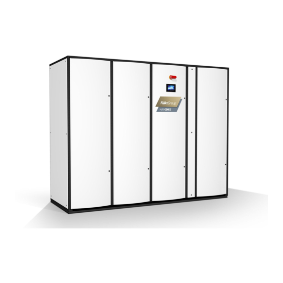
Overview of Units and Scope of Supply Multi-DENCO Product series overview There are 3 versions of the Multi-DENCO product: A-Version, C-Version and X-Ver- sion. These versions have some common elements and also individual characteristics. Fig. 1-1: A Multi-DENCO Unit Common features &... -
Page 15: Denco-Officecool
– Heat pump options available Scope of supply A typical order of a Multi-DENCO unit could consist of (but is not limited to): – Indoor unit of Multi-DENCO configuration with associated internal options pre- installed (unless requiring placement external to the unit or further installation, in which case, hardware is provided loose within the unit) –... -
Page 16: References Within Manual
Overview of Units and Scope of Supply Multi-DENCO References within manual The following references to standards and regulations are made within this manual. These may be updated or revised by the relevant bodies, after publication of this manual. In all instances, review the latest versions for any relevant updates. -
Page 17: Safety And User Information
HIS IS AN ORIGINAL OPERATION MANUAL VERIFIED BY THE MANUFACTURER This document has been developed by the manufacturer specifically for details relating to the Multi-DENCO range. Information within this document may be common to other designs or products, but the information contained is exclusive to Multi-DENCO and non-transferable. -
Page 18: Document Format
Document format Significant information for each chapter will be highlighted in the following format: NOTE! Here you will find additional details on using the Multi-DENCO unit. – This symbol is used to indicate normal lists. • This symbol indicates instructions to follow. -
Page 19: Signs Used Within This Manual
Multi-DENCO Safety and User Information Signs used within this manual 2.4.1 Mandatory Signs General Mandatory Sign Refer to manual or documentation Wear ear protection Wear eye protection Wear safety footwear Wear protective gloves Wear protective clothing Wear a protective mask Guards must be used during operation 2.4.2 Prohibition Signs... - Page 20 Safety and User Information Multi-DENCO 2.4.3 Warning Signs General warning sign Warning of low temperature Warning of electricity Warning of suspended loads Warning of toxic substances Warning of hot surfaces Warning of automatic starting machinery Warning of sharp elements Warning of crushing to limbs...
-
Page 21: Labelling Of Safety Information
Multi-DENCO Safety and User Information Labelling of safety information The following symbols and notices are provided in appropriate places throughout this document to designate the safety instructions: 2.5.1 DANGER – Death/serious irreversible injury Indicates an extremely hazardous situation which will result in death or serious irre- versible injury, if the safety instruction is not followed. - Page 22 Safety and User Information Multi-DENCO 2.5.3 CAUTION – Minor or moderate injury Indicates a hazardous situation which can result in minor or moderate injury, if the safety instruction is not followed. Example: Injury due to sharp cutting edges! • While cleaning care should be taken to prevent risk of injury due to thin fins.
-
Page 23: Safety-Conscious Working
Multi-DENCO system. – No open flames near the system. To comply with EN 378-3 you must wear suitable Personal Protective Equipment (PPE) at any point working on a Multi-DENCO unit. As a minimum we recommend: • Wear safety footwear •... - Page 24 – Greenhouse potential GWP: 1980 – Water hazard class WGK: 1, with a slight risk to water Due to the nature of a refrigeration circuit, a Multi-DENCO system can contain dan- gerously hot and dangerous cold aspects within the same system or circuit. Failure to wear PPE could result in moderate injury.
-
Page 25: Proper Use
Further information can be found in Chapter 6 and Chapter 8 of this manual. Proper use The Multi-DENCO series are designed as indoor units and for connection to a heat rejection system. They are designed for cooling, heating, humidification, dehumidifica- tion and filtering of air at atmospheric pressure. -
Page 26: Disposal
1. 2.13 Environmental considerations Some Multi-DENCO versions can use refrigerants, therefore careful and specific atten- tion is required regarding the handling and storage. Consideration must be given to minimise or eliminate any discharge of refrigerant (accidental or deliberate). Chilled... -
Page 27: Technical Description
– Configuration of network settings 3.1.1 DENCO-OfficeCool This is a variation of a Multi-DENCO unit designed specifically to address the needs of comfort cooling. The design is aimed at reducing fan velocities, reduced sound and features for integration with Local Environment Control Units (LECUs) allowing for adjustable environment to suit comfort levels. -
Page 28: Operating Limits
Default configuration for standard design. 1.00MPa for certain configurations Operating modes A basic Multi-DENCO unit only has the capacity to perform cooling, therefore only being able to control the upper limit of the temperature of the room. Heaters and humi- difiers can be added to the design to allow for control of both the lower limit of tempe- rature and to control the humidification of the room. -
Page 29: Operating Strategies
FreeCool circuit will become available again. Operating strategies Multi-DENCO's inbuilt advance software combined with the latest EC variable techno- logy and networking capability, enables the unit to operate with intelligent control stra- tegies to increase performance or maximise energy savings. In most instances we would recommend using a Running Redundancy strategy to help maximise the energy savings possible. - Page 30 This also saves energy as the Multi-DENCO fans only supply the same amount of air to the floor void, as the amount of air being removed by servers.
-
Page 31: Components
Multi-DENCO Technical Description Components Fig. 3-3: Components Casing The casing design gives the unit a high level of air tightness. The side and rear panels are flat and are flush with the edge of the frame. The front doors are curved and are removable during servicing. - Page 32 Multi-DENCO EC fan All Multi-DENCO units use direct driven, variable speed, high efficiency EC plug back- ward curved fan with three dimensional profiled blades as standard. The impeller is optimally balanced according to ISO1940 and fan speed modulates on standard set- tings.
-
Page 33: Heat Rejection Systems
Condensers can be installed either with a direct 1 to 1 relationship with the indoor unit or 2 condensers can be used with a single Multi-DENCO unit as part of 1 single circuit. This arrangement is refer to as 'twin condensers'. - Page 34 Condensing units perform the same functions as condensers, but they also contain the compressor. Used for the X-Version of Multi-DENCO and H-Version of DENCO-Office- Cool, usually the indoor unit would be used with 1 condensing unit, but for certain unit sizes, 2 condensing units can be used.
-
Page 35: Shipping And Storage
If the unit is stored for a period of time before installation or commissioning, it must be protected from the elements, build-up of dust and dirt! Handling Multi-DENCO units are heavy and can have a high centre of gravity. Failure to safely secure the equipment may result in death or serious injury. •... -
Page 36: Storage
Shipping and Storage Multi-DENCO • Before lifting or shipping the unit, make sure that all mountings are fixed and secured. • Only use lifting gear with sufficient load carrying capacity. • Never use damaged lifting equipment. • Ropes/chains shall not be knotted or be exposed to sharp edges. -
Page 37: Installation
– (If applicable to local regulation) Check installation site fulfill requirements as defined in EN 378-3:2008+A1:2012. – It is recommended that once the the Multi-DENCO unit is located, then it is fixed in placed (e.g. bolted, bracketed etc) to prevent unwanted movement or vibrations. - Page 38 5.1.2 Noise consideration at installation site It is important noise has been considered before the installation. Options are available to equip your Multi-DENCO unit with sound reduction features. Noise is usually a high consideration of DENCO-OfficeCool installations therefore. Ask your local sales repre- sentative for details.
-
Page 39: Substructures
Multi-DENCO Installation Substructures 5.2.1 Under unit drip tray To protect the floor underneath a unit from any condensation, a drip tray can be moun- ted underneath. The drip tray can be used in a raised floor (underneath a base frame) or with a plinth. - Page 40 Installation Multi-DENCO 5.2.5 Ceiling connection duct For units that wish to connect with a suspended ceiling, a connection duct can be used to create an air path. The ceiling connection duct is made of the same material as the unit's panels. The height of ceiling connection ducts are made to specification and they can bolt onto the top of the close control unit through a service panel on either side.
-
Page 41: Unit Placement
• Never stand beneath suspended loads. Multi-DENCO units are heavy and can have a high centre of gravity. The unit, or parts of the unit can, tip and fall. Failure to safely install the equipment may result in death or serious injury. -
Page 42: Clearance And Access
2000 Tab. 5-1: Fig. 5-8 Columns A, B and D are recommended minimum values to ensure satisfactory operation by your Multi-DENCO unit. Column C is the mandatory minimum values to ensure serviceability for your Multi-DENCO unit. Note! Column C is ONLY the minimum service requirements and does not reflect any safety requirements that may affect your local region. - Page 43 Installation 5.4.2 Access Multi-DENCO has been designed to be serviceable exclusively through the front doors of the unit (the curved panels). Access to the right hand side panel (as you face the unit) can increase the speed of service, but is not mandatory.
-
Page 44: Installing Enclosed Accessories
Multi-DENCO Installing enclosed accessories Below is a list of items or options that could be supplied with your Multi-DENCO unit. The accessories could be inside of the unit on delivery or as a separate package. The below items will need further installation once the unit is in place. - Page 45 Multi-DENCO Installation 5.5.4 Water detection Important Note! The water detection tape should be installed prior to commissioning and the end user should be made aware that, upon contact with water, an alarm is generated by the controller as an indication of the presence of water. This alarm is not critical to the unit's operation, therefore the unit will continue to operate.
- Page 46 5.5.6 Remote monitoring touch screen display • The display can be mounted up to 50 m away from the C5-12 controller within the Multi-DENCO unit. • A 24 VAC supply is required, local, to power the display, together with a two core screened data cable that networks the display to the pLAN connection on the C5-12 controller.
-
Page 47: Installation Of Outdoor Units
Installation Installation of outdoor units Note! It is mandatory to connect the Multi-DENCO indoor unit to a heat rejection unit. This is achieved typically in five different forms, depending on the version used: – Condensers (DMOUCD) – Condensing units (DMOUUD) (including heat pumps) –... - Page 48 Installation Multi-DENCO 5.6.3 Positioning The condenser must be installed on a level surface that can support the weight of the equipment and allowing for access from all sides. If multiple condensers are used for 1 indoor unit, the condensers must be installed on the same level and the same distance to the indoor unit.
- Page 49 Multi-DENCO Installation 5.6.4 Clearances Condensers must be located in an unobstructed position to ensure adequate air circu- lation through the cooling coil. Care must be taken to avoid air recirculation from one unit to another. Clearances around the condensers must be in accordance with condenser specific drawings supplied in the unit documentation.
-
Page 50: Fan Touch Protection
It is extremely important that no one can come into contact with the fans within the Multi-DENCO units during operation or immediately after operation. Users must wait 5 minutes after turning off a Multi-DENCO unit before removing any safety guard, to ensure fans have come to a complete stop. - Page 51 Multi-DENCO Installation It is the responsibility of the installer to carry out the assessment and to prepare the EC Declaration of Conformity. For the installation of the interconnecting pipework and electrical cabling, the declaration must then be signed by your legally responsible representative (which may be the Managing Director of the Company).
-
Page 52: Medium Connections
Only copper refrigerant lines meeting EN 12735-1:2010 standards shall be used for refrigeration pipework installation. R410A is the standard refrigerant used within Multi-DENCO units, ensure that pipework used is suitable for the higher pressures used with this refrigerant. The relevant requirements of the standard, especially apply to: –... - Page 53 Multi-DENCO Medium Connections 6.2.2 Material quality For refrigeration pipework: – Copper tube quality must be the equivalent of EN 12735-1 – Refrigeration grade copper must be used – Pipework must be cleaned and dehydrated – Use of joints, bends or sets must be kept to a minimum –...
- Page 54 NOTE! For condensing units, see separate installation manual. On Fig. 6-1 and Fig. 6-2 the labels are as follows: Discharge line (hot gas) from the Multi-DENCO indoor unit Branches of discharge line Liquid Line returning to the Multi-DENCO indoor unit...
- Page 55 Multi-DENCO Medium Connections Horizontal airflow Isometric View Top View Fig. 6-1 Vertical airflow Isometric View Side View Fig. 6-2 FläktGroup DC-2013-0101-GB • Subject to modifications • R4-05/2018...
- Page 56 All pipework, which is subject to changes in temperature, expands and contracts. The routing and joining of the pipework must be capable of absorbing this movement. An example of the rate of expansion on a Multi-DENCO unit is as follows: Pipe Pipe Operating Expansion in 0 °C...
- Page 57 – Any painting of insulation installed outdoors must be completed in line with manu- facturer's guidelines Each site must be individually assessed depending on pipework exposure, position, length and accessibility to pipework, but for Multi-DENCO units: A-Version: Discharge lines and liquid lines do not need to be insulated, but may be required due to site conditions and accessibility to pipework.
- Page 58 Flux left on the pipes looks unsightly and can cause oxidisation, pitting and prematurely age the tubing. 6.2.9 Oil traps Fig. 6-4: Requirements of discharge lines on Multi-DENCO units FläktGroup DC-2013-0101-GB • Subject to modifications • R4-05/2018...
- Page 59 On certain downflow units, access to the refrigeration pipework connections can be dif- ficult (especially if there is no side access to the unit). Multi-DENCO units are designed to allow for the removal of fan closest to the pipework to make installation easier.
-
Page 60: Refrigerant Pipework Testing Procedures
A pressure test certificate must be signed, witnessed and passed to the commissioning engineer. NOTE! The use of 'tracers' or 'dyes' are not permitted on Multi-DENCO units under any cir- cumstances. NOTE! Depending upon your commercial agreement, you may be required to perform the vacuuming and oil and refrigerant pre-charging of the system, before the commis- sioning engineer's arrival. - Page 61 Multi-DENCO Medium Connections 6.3.1 A-Version: Size 010 to 065 For standard units, all devices fitted to the low pressure side of the system are suffi- ciently pressure rated and can remain connected to the system during pressure testing. 1: Ensure that the adjacent area is clear of non-essential staff, complete a risk assessment and establish an exclusion zone for safety purposes.
-
Page 62: Humidifier Water Connections (Optional)
Medium Connections Multi-DENCO 6.3.3 X-Versions and DENCO-OfficeCool H-Versions For guidelines on how to perform pressure testing for these installations, please refer to the separate installation manual. Some condensing units may be delivered with a 'pre-charge' of refrigerant: ensure this is not released during pressure testing. - Page 63 Multi-DENCO Medium Connections NOTICE ON WATER USE! – Under no circumstances should the water supply be fed from a water softening system. – Do not add disinfectants or anti-corrosive substances (irritants). – It is not recommended to use industrial water or chemically and bacteriologically polluted water for cooling circuits.
-
Page 64: Connecting Condensate Drain
Medium Connections Multi-DENCO Connecting condensate drain The following should be considered during installation: Air handling unit – Drainpipe runs shall be 22 mm OD or larger of water carrying quality of either copper or high temperature rigid plastic and should be adequately supported at regular intervals and have a slope of at least 2 % to ensure drainage. -
Page 65: Connecting Water Pipework
Chilled water pipework connections are placed at the bottom of the Multi-DENCO unit and are terminated with flanges, BSP connectors or just copper tubes (solder connec- tion). Please refer to the unit dimensional drawing. - Page 66 Medium Connections Multi-DENCO AIR HANDLING UNIT CASING CHILLED WATER RETURN TO RECOMMENDED CHILLED WATER MAIN/CHILLER EXPANSION TANK WATER FILL RECOMMENDED CONDENSATE TRAY/DRAIN CHILLED WATER SUPPLY FROM CHILLED WATER MAIN/CHILLER LINE TYPES: HUMIDIFIER CONDENSATE / WATER SUPPLY HUMIDIFIER DRAIN CHILLED WATER SUPPLY...
- Page 67 Multi-DENCO Medium Connections 6.6.1 Water quality Recommendation on water quality for chilled, warm and condensing water circuits/heat exchanger: Parameter Value Unit pH-value (at 20 °C) 7.5 - 9 μS/cm Conductivity (at 20 °C) < 700 Dissolved solid materials (cR) mg/l <...
- Page 68 Medium Connections Multi-DENCO When using glycol: • Water-glycol mixture does not have a burst effect starting from frost resistance of - 20°C, as slush ice forms when the mixture is cooled below the freezing point. • Use only one type of glycol, do not mix different types.
- Page 69 Multi-DENCO Medium Connections 6.6.4 Hot water heating (optional) The L.P.H.W. (low pressure hot water) coil is fitted with a modulating three port valve, which is wired and fitted within the unit casing. It is important to consider the fitting of commissioning sets in the supply/return pipe- work to allow accurate water measurements and flow adjustments.
-
Page 70: Electrical Connections
Electrical Connections Multi-DENCO Electrical Connections When making an electrical installation, the installer must: • be qualified and licensed according to local and regional regulation. • Observe regulation relating to electrical power supply for the installation region • Observe the Low Voltage Directive 2014/35/EU •... -
Page 71: Connecting Mains Power Supply
7.2.4 Cable routing inside unit – Multi-DENCO units are designed for cable entry from the BOTTOM of the unit. – Secure any interconnecting cables within the unit and ensure that the cables cannot make contact with the fan or any hot components. -
Page 72: Connecting Outdoor Unit
We STRONGLY recommend that the outdoor unit should be connected to the indoor unit for its power supply. 7.3.1 A-Version Condensers (DMOUCD) that are supplied with A-Version Multi-DENCO units are pro- vided with their OWN SEPARATE ISOLATOR. For condensers, the following power and controls layouts are possible: Fig. - Page 73 NOTE! Power supply is dependent on outdoor unit's size. See electrical drawing for details. Multi-DENCO X-Version and DENCO-OfficeCool units are provided with PAC interface control boards to allow for control of condensing units. If 2 outdoor units are required, 2 boards will be provided.
-
Page 74: Connecting Signal Cabling
– 2 core screen cable for data signal to the unit's C5-12 controller – A 24V AC power source (this can be from the Multi-DENCO unit) The remote display can be installed up to 50m away from the Multi-DENCO unit. In all installations, consider the effect of signal attenuation and voltage drop. - Page 75 Electrical Connections 7.4.3 Unit networking When multiple Multi-DENCO are located within the same cold space, it is best practice to set them up in a network. Creating a network has the advantages of being able to perform sensor averaging or rotating standby units.
-
Page 76: Customer Terminals On C5-12 Unit Controller
Electrical Connections Multi-DENCO Customer terminals on C5-12 unit controller Unit Network/Remote Display/Unit Display Air intake sensor Air discharge sensor C5-12 CONTROLLER TERMINALS Serial Card Interface Card (Optional) CUSTOMER TERMINAL BLOCKS Condensate Critical Maintenance Remote contact Emergency off Run status #... -
Page 77: Commissioning
– Different options can require different commissioning procedures (e.g. winter kit). – This chapter applies to initial commissioning as well as re-commissioning due to extended shut down periods or relocation. – Only R410A can be used in Multi-DENCO systems. Refrigerants poses hazardous risks: – Refrigerant cylinders can be heavy. -
Page 78: Pre-Commissioning Procedure
Commissioning Multi-DENCO 8.1.2 Suggested equipment It is important that all equipment is safe to use, is calibrated and is portable appliance tested (PAT) where appropriate. Below is a list of recommended equipment to be able to fully commission a unit: –... - Page 79 • Check that a copy of this manual is available • Check a copy of the electrical drawings/wiring diagrams are available Multi-DENCO unit • Check the unit internally and externally for any damage • Photograph and record any damage (including shipping damage) and inform the end user •...
- Page 80 Commissioning Multi-DENCO 8.2.3 Checking refrigerant circuits (A-Version, X-Version & H-Version) • Check the oil traps are installed and to specifications (chapter 6.2.9) • Check that pipework is sized correctly and within the limits (e.g. length between indoor and outdoor unit) (chapter 5.6.2) •...
- Page 81 It is as follows: Initial evacuation • Connect the service manifolds to the Multi-DENCO system in an appropriate and safe manner. • Make sure that all system valves are open (i.e. shut off valves) •...
- Page 82 Commissioning Multi-DENCO NOTE! Multi-DENCO units can contain two different types of compressors – each with their own oil type. Please follow the below recommendations: A-Version - Size 010 - 065 A-Version - Size 092 - 130 FV50S POE 160SZ Emkarate RL68H...
-
Page 83: Commissioning Procedure
– Current conditions (during commissioning) – (Possible) future conditions For example, attempting to commission a Multi-DENCO A-Version unit in a room with no heat source is difficult, as you would not be able to give a consistent operation to observe refrigerant charge. Alternatively, commissioning a unit on a cold day could result in lower condensing temperatures, which may cause over-charging of a unit. - Page 84 • Ensure the outdoor unit's isolator is set to 'ON' (if applicable) • Enable any 'in-line' isolation for the Multi-DENCO unit • Set the door interlock isolator (if fitted) to the 'ON' position •...
- Page 85 Details of how to change values in the C5-12 controller are available in the Multi-DENCO con- trols manual.
- Page 86 Commissioning Multi-DENCO Procedure With a stable system, additional refrigerant can be progressively added to the circuit to bring the system to the required charge. When adding refrigerant, the following proce- dure and advice applies: • Refrigerant should be added to the suction line as liquid •...
- Page 87 Function Test of Safety Device(s) Multi-DENCO units are fitted with High Pressure (HP) switch(s) to mechanically protect the refrigeration circuit. After charging, these MUST BE TESTED. For details of the procedure, please refer to the controls manual.
- Page 88 Commissioning Multi-DENCO 8.3.6 Commissioning chilled water circuits The following procedure applies to any water circuit used within a Multi-DENCO system (C-Version, CombiCool circuit, O-Version etc). Procedure • Check for an established water flow • Check that any temperature sensors are securely fastened to the correct pipework •...
- Page 89 2-port Pressure Independent Control Valves (PICV) NOTE! The following instructions are for 2-port PICV valves used with C5-12 controllers in Multi-DENCO units. For all other configurations or equipment please see separate manuals or contact your local office. FläktGroup DC-2013-0101-GB • Subject to modifications • R4-05/2018...
- Page 90 Commissioning Multi-DENCO To set up the maximum design chilled water flow rate, on site: • The unit must be powered on, pre-commissioned and running under automatic control • The chilled water pump must be operating to provide pressure differential across the unit of 100 kPa (minimum 50 kPa, maximum 350 kPa) •...
- Page 91 Multi-DENCO Commissioning Procedure 1. Calculate the 'system refrigerant'. – This is the refrigerant required to charge a standard system without a winter kit option (indoor/outdoor unit and interconnecting pipework). 2. Calculate the refrigerant required to fill the liquid receiver to 80% (see Tab. 8-4).
- Page 92 Commissioning Multi-DENCO 5. When liquid is observed, you will find that you have not use all of the estimated refrigerant (system and liquid receiver) – You will have only filled the liquid receiver to its minimum level (Fig. 8-2) Required level Level when 'liquid flashes' are observed.
-
Page 93: Post-Commissioning Procedure
As mentioned previously, it is very important that you submit a copy of the 'Multi-DENCO Commissioning Report' (chapter 13.3) to your local sales/service repre- sentative, so that this can be retained against the project. Failure to do so may invali- date warranty. -
Page 94: Operation
– Location of power distribution board isolator – Location of the mains isolator – Either fitted within the door of the Multi-DENCO unit or within 1m of the unit – Location of circuit breakers (MCBs) inside the Multi-DENCO unit – Shut off (isolation) valves for the Multi-DENCO unit including (if applicable): –... - Page 95 Multi-DENCO Operation 9.2.2 The home screen (C5-12) 1: Unit ON/OFF (by keyboard) Unit Number (for networking) 2: Unit Status 10: Model Reference 3: Alarms Page 11: Icon if any alarms are active 4: Unit Graphs 12: Date 5: Login 13: Unit function Icons...
-
Page 96: Alarms And Error Messages
Once fan momentum has ceased and the inverter energy discharged, you can open the doors and conduct work. • To stop the Multi-DENCO unit, simply press the ON/OFF button on the home screen. The screen will display 'UNIT OFF BY KEYBOARD' if successful. -
Page 97: Servicing And Maintenance
Multi-DENCO Servicing and Maintenance 10 Servicing and Maintenance Regular preventative maintenance of your equipment is strongly recommended to ensure that it is kept in excellent operating condition. Along with equipment recommended in Chapter 2, we recommend that a protective mask is worn during service and maintenance. -
Page 98: Maintenance Access
Fig. 10-1 10.2.1 Example Maintenance schedule Below show an example maintenance schedule for a Multi-DENCO unit. We advised the below is the minimum requirements. Most situations will require further actions and a shorter time interval to ensure good operating conditions. - Page 99 Multi-DENCO Servicing and Maintenance Interval Action 1: Check for any outstanding alarms. Daily 2: Check display for good operation. 3: Visual inspection of exterior condition of the unit. 4: Visual inspection in and around the unit for the presence of refrigerant oils, which may show signs of a leak.
-
Page 100: Refrigerant Leak Testing
– Changes or extensions to the system – Suspicions of refrigerant leakage – On Multi-DENCO systems with a R410A refrigerant charge of 2.4 - 23.9 kg (equiva- lent 5 - 50 tonnes CO ) a yearly leak test is mandatory. -
Page 101: Closing Down Procedure
Multi-DENCO Servicing and Maintenance 10.6 Closing down procedure It is essential for starting, closing down, emergency operation and fault finding to know the location of the following components: – Location of isolator for power distribution to the unit – Main Isolator (integral to unit or local position) –... -
Page 102: Logbook & Eu Regulation
Servicing and Maintenance Multi-DENCO 10.7 Logbook & EU Regulation A logbook should be available throughout the working life of the equipment. In the EU this is a legal requirement if the system charge is 2.3 kg or above. The logbook needs to be updated after each maintenance to comply with EN 378-4:2008+A1:2012 and should include the following information: –... -
Page 103: Fault Finding And Troubleshooting
Fault Finding and Troubleshooting 11 Fault Finding and Troubleshooting The Multi-DENCO range is designed to perform its primary function: cooling of the con- trolled space, for as long as possible. As long as a consistent and suitable power sup- ply is given to the unit, only 'Critical' alarms will stop the unit performing its primary function. -
Page 104: Common Issues
(electrical power, water, free airflow etc.). Multi-DENCO units use fans which are regulated independently by the main control board. Removing guards whilst unit is operational risks death or serious injury. - Page 105 Multi-DENCO Fault Finding and Troubleshooting Fault Possible Reason Possible Remedy High pressure in refrigeration sy- Too much refrigerant within Refer to commissioning report and compare current conditi- stem system ons with conditions during commissioning. If significant changes then perform re-commission the unit.
-
Page 106: Dismantling And Disposal
Dismantling and Disposal Multi-DENCO 12 Dismantling and Disposal 12.1 Dismantling To dismantle a Multi-DENCO unit, proceed as follows: • Ensure all incoming electrical connections are isolated and cannot be inadvertently energised. • Inverter technology and rotating fans required at least 5 minutes from electrically isolating the unit before any doors or panels can be removed. -
Page 107: Disposal
• Once mechanically and electrically separated from the system, attend to releasing the Multi-DENCO unit from any fixings to the floor or other sub-structures • Prepare the unit for handling and transportation as per chapter 4 12.2 Disposal... -
Page 108: Appendix
This is the template for recording the system pressure test conducted on the Multi-DENCO circuit, once the mechanical installation has been completed. 13.3 Multi-DENCO Commissioning Report (DQA 890) This is the template for the commissioning report of Multi-DENCO units. FläktGroup DC-2013-0101-GB • Subject to modifications • R4-05/2018... -
Page 109: Pre-Commissioning Checklist (Dqa 880)
Multi-DENCO Appendix 13.1 Pre-Commissioning Checklist (DQA 880) e – Co ommi ission ning C Check klist As a pre e-requisite to acceptin g a firm boo oking for co ommissionin ng we need clarification n that all aspects s of the inst... - Page 110 Appendix Multi-DENCO Tick Boxes Checkl ist Item Comments If chilled d water or c condenser w water system is to be fille ed with a gly ycol mix ha this bee en done and d accurate concen tration read dings availa...
- Page 111 Multi-DENCO Appendix Comme ents: Comple eted By: Signatu ure: On Beh half Of: Date: Failure to comp plete this form or failure to ha ave all require d items ready f for commissio oning may resu in an abort tive visit by ou...
-
Page 112: Pressure Test Certificate (Dqa 653)
Appendix Multi-DENCO 13.2 Pressure Test Certificate (DQA 653) Pressure Test Certificate GEA Heat Exchangers Limited Dolphin House - Moreton Business Park Moreton on Lugg - Hereford - HR4 8DS Telephone: +44 (0) 1432 277277 Fax: +44 (0) 1432 268005 Customer... -
Page 113: Multi-Denco Commissioning Report (Dqa 890)
Multi-DENCO Appendix 13.3 Multi-DENCO Commissioning Report (DQA 890) Multi Denco Commissioning Record Book Before working on this equipment, ensure that all incoming electrical connections are isolated and checked as voltage free by a competent person. FAILURE TO DO SO MAY RESULT IN SERIOUS INJURY OR DEATH Refer to appropriate electrical wiring schematic for all external wiring Section A: 1 copy for completion by contracts engineer in respect of each model or variant on site. - Page 114 Appendix Multi-DENCO Multi Denco Commissioning Record Book Air Volume Checks Measured Air Volume Air On Temperature °C Max Fan Speed Setting % or V Air Off Temperature °C Min Fan Speed Setting Air Flow Fail Setting Check % or V...
- Page 115 Multi-DENCO Appendix Multi Denco Commissioning Record Book Chilled Water (if option fitted) Option Fitted to Machine Yes/No CW Flowrate Double Reg Valve Setting No / kpa CW Water Inlet Temp. °C CW Water Outlet Temp °C Option Fitted to Machine...
- Page 116 Appendix Multi-DENCO Multi Denco Commissioning Record Book F-Gas regulation No 842/2006 Record Log Sheet Information For Owners Use - Answer All Questions Plant Name Reference Number Location of Plant Serial Number Plant Operator Plant Operator Operator Contact Cooling Loads Served...
- Page 117 Multi-DENCO FläktGroup DC-2013-0101-GB • Subject to modifications • R4-05/2018...
- Page 118 Multi-DENCO FläktGroup DC-2013-0101-GB • Subject to modifications • R4-05/2018...
- Page 119 Multi-DENCO FläktGroup DC-2013-0101-GB • Subject to modifications • R4-05/2018...
- Page 120 WWW.FLAKTGROUP.COM MULTI-DENCO FläktGroup is the European market leader for smart and energy efficient Indoor Air and Critical Air solutions to support every application area. We offer our customers innovative technologies, high quality and outstanding performance supported by more than a century of accumulated industry experience. The widest product range in the market, and strong market presence in 65 countries worldwide, guarantee that we are always by your side, ready to deliver Excellence in Solutions.
Need help?
Do you have a question about the Multi-DENCO and is the answer not in the manual?
Questions and answers