Table of Contents
Advertisement
MAIN INSTALLATION MANUAL
®
FOR AN AURAGEN
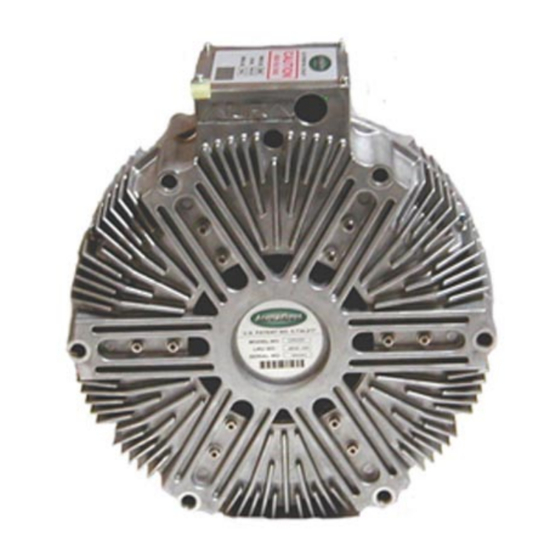
INDUCTION
POWER SOURCE
Vehicle Powered
Mobile Electric Power
Models G5000, G6000D, G6000X, G8500, G8500X
Aura Systems, Inc.
2335 Alaska Avenue, El Segundo, CA. 90245
Phone: (310) 643-5300 - Fax: (310) 643-7457 - Toll Free (800) 909-AURA
Web Site: www.aurasystems.com
Advertisement
Table of Contents


Need help?
Do you have a question about the G5000 and is the answer not in the manual?
Questions and answers