Advertisement
Quick Links
DZ185
OPERATOR'S MANUAL
137
120
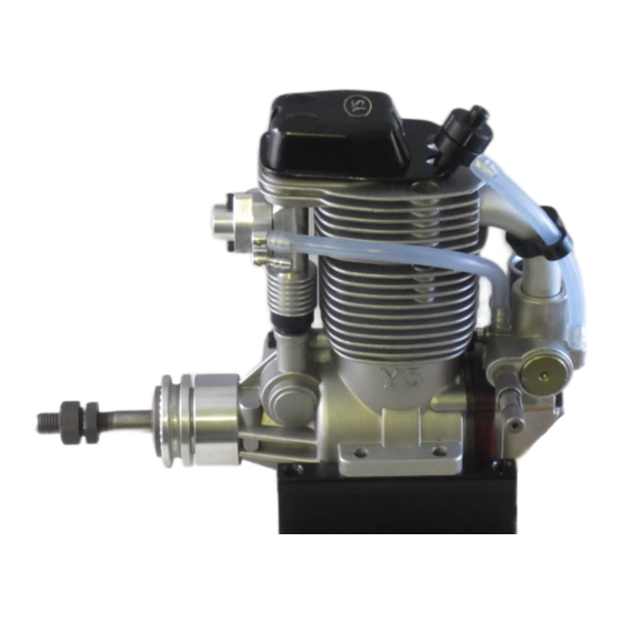
FIG 1
63
25
Regulator
Front Nut ( HEX13)
Rear Nut ( HEX13)
Front Mount
149.5
Safety Instructions
In order to use the engine, please read through this instruction manual care-
fully. This is a complex, high-performance engine. If you have any difficulties
for understanding any part of this instrucyion manual, please contact the
hobby shop from whom you purchased the engine, or contact us directory.
1. The propeller double locknut assembly supplied with the engine must be
used when mounting the propeller.
2. Select a good quality propeller and follow the manufacturer's instruction.
3. Choose a propeller size that will not allow the engine to exceed the maxi-
mum practical RPM in flight.
4. Always ensure that no people are in front of or besides the propeller while
thet engine is running.
5. To start the engine, set the throttle to the idle position and use an electric
starter.
6. After starting the engine, always move behind the propeller to adjust the
needle settings.
7. The engine becomes extremely hot both during and after engine runs. Do
not touch the engine, exhaust header, muffler, or any parts attached to the
engine while it runs or before it has cooled down.
8. The ignition systtem develops an extremely high voltage, so please be
careful during its operation. It is very dangerous to modify the ignition sys-
tem by yourself.
9. Sparking noise may cause interference and shorten the rangr of the
aircraft's receiver. Please perform a range check with the engine running on
the ground before you fly. If there are any problems with range, DON'tT FLY.
10. If the engine runs incorrectly, DON'T FLY.
11. Do not use this engine for anything other than radio controlled airplanes.
Do not use it for radio controlled helicopters.
12. You have full responsibility while you operate the engine. Please be
extra careful for your safety and the safety of tothers wgenever you operate
the engine.
Installation
WE RECOMMEND THAT THIS ENGINE BE MOUNTED ON A SHOCK ABSORB-
ING SOFT MOUNT
1
Connect the engine to the fuel tank and CDI system as shown in fig.1.
The battery and switch for the CDI unit is not supplied with the engine. The soft
mount and fuel filter are optional.
Bore
35mm
Stroke
31.8mm
Weight
960g
Displacement
30.6cc
Practical rpm
1,000~9,000rpm
14
Needle Valve
Fuel Filter
Tube A
Air
Tube B
Break-in Needle
Fuel Tank Clunk
Rear Mount
2. The recommended fuel tank size is 500cc to 700 cc(18oz to 24 oz). A standard
clunk type fuel tank may be used. If this type of tank is used, you must use the spe
cial clunk supplied with the engine. Please note that with this clunk, some
fuel cannot be drained from the tank. As soon as any part of the clunk becomes
exposed, the engine will stop due to air entering the fuel pump.
3 Always use a fuel filter. We recommend YS filter ( 6720 ). With this filter, you must
remove the cloth portion of the filter and leave both the metal filter screens in place.
Fuel
1. Use a good quality alcohol based model engine fuel containing 10% to
25% nitro, and oil content 5% to 25%. You can not use gasoline fuel.
2. When you filling the tank, disconnects Fuel Tube "A", or Fuel Tube "B"
see "Fig.1" from connecting tube to filling. If you use "T" nipple on the fuel
line to filling, use fuel stopper on the Fuel Tube "A" see "Fig.1" to avoid fuel
in to the engine.
Propeller
1. Due to the high output power of the DZ185 engine, it is supplied with
a double locknut system for added safety. Mount the propeller and tighten
the rear nut. Next, tighten the front nut. The rear nut has an offset shoul
der so the front nut will secure itself to the rear nut.
2. Please retighten propeller nut periodically.
3. Select a propeller that will allow the engine to run at maximum speed be
tween 6,000 to 8,000 rpm range.
4. We recommend sizes 19X11 to 21X10. Other prop sizes may be
used as long as the correct rpm range.
High Speed Needle Adjustment
1
Adjustment of the high speed is done by the carburetor needle
valve.When the needle valve is turned clockwise, the mixture is
leaner. When it is turned counter-clockwise, the mixture is richer.
A good starting position for the high speed needle valve is 2 turns
open from the fully closed position. At this setting the engine will
be very rich and may die when you remove the glow driver.
If this happens, turn the needle valve in 1/2 turn and try again.
The final running setting for the high speed needle will be approx-
imately 1 to 1-1/2 turns open from fully closed.
2
When the engine is started, open the throttle gradually. Next, find
the peak position ( highest RPM ) by adjusting the needle valve.
Then the needle valve should be opened approximately 1/8 _ 1/4
turns from full RPM to achieve best performance.
Break in needle
Open break-in needle half turn in counter clockwise direction while
break-in. After break-in, close it to 1/6 turn or fully closed position. By
this procedure, fuel flows into crankcase through break-in needle. It
makes lubrication better and also prevents percolation (vapor rock) .
We recommend to open it a little under high tempreture in summer time.
NOTE: Engine power decrease as break-in needle open. When you
need maximum power, close the needle fully.
Breake-in
1. Start the engine with high speed needle valve open 1 1/2 - 2 turns
and the brek-in needle open 1/2 turn from the fully closed position
and with the throttle at the idle position.
2. After starting the engine, increases the RPM gradually by operating
the throttle. Do not suddenly apply full throttle.
3. If the mixture is too rich and the engine misfires, turn the needle
valve clockwise to make the mixture leaner.
4. Breake-in the engine with one or two tanks of fuel (500cc) on the
ground, running at the richest possible mixture setting.
5. Close the break-in needle till 1/6 or fully closed position after break-in.
Idling adjustment
1. To get 1,200rpm to 2,000rpm idling.
2. When the regulator is turned counter-clockwise, the idle mixture is leaner.
When the regulator is turned clockwise, the idle mixture is richer. Adjust
regulator by turn 45 degree at a time.
3. If idle mixture is too rich, gradually rpm drops and stops after continuous
idling. If engine stops when you change attitude of airplane on the ground
also too rich on idle mixture. If mixture is too lean on idle, rpm is go up
and down and not keep stable when you make continuous idle.
Glow Plug
Select the most appropriate glow plug from those designed specifically for
4 cycle engines. Glow plug selection greatly affects the maximum engine
output and low idle. If RPM's decrease or stop when the booster cord is
removed, replace the plug. We recommend the YS#4 plug for maximum
performance.
Tappets Adjustment
1. Tappet clearance is preset at the factory.
2. Clearance adjustment may need after first one hour running time due to
initial wear. After first adjustment, clearance should be checked as normal
maintenance for every 10 hours running for maintain maximum perfor
mance.
3. Clearance adjustment should be done when the engine is cool.
4. The proper clearance should be set at 0mm (0.000") to 0.1mm (0.004").
The adjustment is achieved by loosening the lock nut see "Fig.2" and
turning the adjustment screw see "Fig.2". The engine must be at top
dead center on the compression stroke before any adjustments are made.
This engine runs best with the valves set at a tight setting. If the valves
are set too loose, power will be affected.
Fig2
Tappet Clearance
Cam Gear Timing
If for some reason you have to disassemble your engine, please follow
these important steps on reassembling the cam gear.
1. Remove the carburetor and back plate assembly. Notice the impression
mark or dot opposite the rod journal on the crankshaft.
2. This mark is to point straight down or lined up with the outer case seam
line at the bottom and hold crankshaft securely.
3. Reinstall the cam with the dot facing you. After you fully installing cam
and then check dot should be pointing straight down will give you right
timing.
Operation of YS Super Mount (Option)
1. It is hold by 4 screws, 2 on the front ring and 2 on the rear soft mount.
There are two different height of spacer we provide.
A set spacer (MN110S) : 10mm thickness
B set spacer (MN111S) : 4mm thickness
2. Please be sure not to hit any part of the fuselage by the engine after it
installed.
3. If damper oil is leaked, refill TAMIYA damper silicon oil #600. Damper is a
consumption parts, please exchange if you fined worn or some defect.
Cleaning
This engine is using silicon gaskets, "O" rings etc. Please use methanol or
model engine fuel for cleaning. Do not use Kerosene, Gasoline, Machine
oil, Automobile parts cleaner or house hold lubricants to clean. It will harm
silicon parts.
Engine Cooling
Be sure to secure cooling air for engine cooling. If it is not enough cool-
ing air for the engine causes heat up the regulator and carburetor to make
vaporized or percolates the fuel and will get deteriorations of engine perfor-
mance or stop the engine. Please read carefully below for provision.
1. Please open air intakes and outlets as big as possible.
2. Take off cowling when you make long engine adjustment included idle
adjustment. When air temperature is high, it may heat ups the regulator
and carburetor to make vaporized or percolate the fuel even with out cowl
ing. If it happens, wait till engine well cooling down before you restart and
adjust.
Rusting provision
Do not leave fuel in the engine after you finished for day. If you store the en-
gine long period of time, few drops (about 1cc) of model engine lubricant oil
from carburetor and clank several times. Do not use Automobile engine oil.
They will not mix together with alcohol.
Parts and Repair Service
If you can not find repair parts form hobby shops, you can order parts direct
to our factory. We also do repair your engine at our factory. If you need
repair service, please make detailed of states and send together with the
engine.
Warranty
We strictly inspect each process of production from parts to final assemble
for keep good quality. If a performance deteriorates or part fails due to a
manufacturing error under normal usage will repair no charge with in 1 year
starting from the date of purchase. Warranty will not cover normal wear.
Even with in 1 year warranty term, improper disassemble or assemble, un-
der improper usage, any modification will avoid this warranty and there will
be normal charge for parts and labors.
Advertisement

Related Manuals for YAMADA DZ185

Summary of Contents for YAMADA DZ185
- Page 1 2. Clearance adjustment may need after first one hour running time due to 1. Due to the high output power of the DZ185 engine, it is supplied with not touch the engine, exhaust header, muffler, or any parts attached to the initial wear.
- Page 2 Drive washer retainer F8081 Intake pipe F1269 Intake pipe O-ring E4079 Wrist pin access plug F1266 Propeller washer YAMADA MFG. CO.,LTD. F2267 Propeller nut set F2084 Wrist pin access screw 67 TUCHITORI, INUYAMA, AICHI, JAPAN 484-0917 F4088 Check valve E1273S...
Need help?
Do you have a question about the DZ185 and is the answer not in the manual?
Questions and answers