
Subscribe to Our Youtube Channel
Related Manuals for FlexGain FOM16

Summary of Contents for FlexGain FOM16
- Page 1 VER :2.0...
-
Page 3: Table Of Contents
FOM16 Installation Description FOM16-V2.0-20021114 FOM16 Installation Description Table of Contents 1. PREVIOUS PREPARATION............................. 1 2. MECHANICAL INSTALLATION ..........................2 3. ELECTRICAL INSTALLATION..........................4 4. OPTICAL INSTALLATION ............................7 5. FRONT PANEL INDICATOR ........................... 7 6. FRONT PANEL OPERATION ..........................10 6.1 M... -
Page 5: Previous Preparation
FOM16 Installation Description FOM16-V2.0-20021114 1. Previous Preparation 1.1 Tools and Materials Ground Strip Wire cutters Multi-meter Power cable (AWG 8, Single-bone): Red and black both Ground cable (AWG 14, Single-bone): Green FC/PC Patch cord: FC/PC connectors, 1310mm single mode fiber... -
Page 6: Mechanical Installation
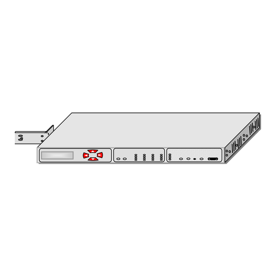
2. Mechanical Installation 2.1 FOM16 is a standard 1 RU unit, which can be mounted on 19 or 23-inch rack. It also works as a desktop unit. The front view and the rear view are shown in Fig.1 and Fig.2, respectively. - Page 7 FOM16 Installation Description FOM16-V2.0-20021114 Fig.4 23-inch rack mountable (II) Fig.5 19-inch rack mountable (I) Fig.6 19-inch rack mountable (II)
-
Page 8: Electrical Installation
3. Electrical Installation 3.1 FOM16 can be either AC- or DC-powered. If both AC and DC are fed at the time, The AC power is selectable internally first and the DC power is used as a back up power source. - Page 9 FOM16 Installation Description FOM16-V2.0-20021114 75 Ω 75 Ω TXTIP4 TXTIP1 TXTIP4 TXTIP1 TXTIP3 TXTIP2 TXTIP3 TXTIP2 RXTIP1 RXTIP4 RXTIP1 RXTIP4 RXTIP3 RXTIP2 RXTIP3 RXTIP2 GROUP D GROUP C 75 Ω 75 Ω TXTIP4 TXTIP4 TXTIP1 TXTIP1 TXTIP3 TXTIP2 TXTIP3 TXTIP2...
- Page 10 Alarm Contact Fig.11 Alarm contact pin assignment 3.7 FOM16 is equipped with a rear LAN port that is an RJ-45 connector. This port operates at a rate of 10 Mbps over an ETHERNET cable. Pin assignment is shown in Fig.12.
-
Page 11: Optical Installation
4.3 When planning the routing of fiber optic cables, avoid sharp bends. 5. Front Panel Indicator Fig.11 shows the front view of the FOM16, and Table 1 lists the functions of the FOM16 controls, connectors, and indicators, located in the FOM16 front panel. The index numbers in Table 1 correspond to the item numbers in Fig.13. - Page 12 FOM16 Installation Description FOM16-V2.0-20021114 Table.1 FOM16 Controls, Connectors and Indicators NO. Controls or Indicators Function Description Two by twenty (2×20) characters LCD to show menu items. display window Enter key pad Used to move down the menu tree or enable a selection.
- Page 13 ON when any near end alarm occurs. Far End indicator ON when any far end alarm occurs. Abnormal operation ON when FOM16 is in abnormal operation, that is, any of loopbacks indicator of tributaries and optical links is activated. Alarm-Cut-Off...
-
Page 14: Front Panel Operation
FOM16 Installation Description FOM16-V2.0-20021114 6. Front Panel Operation The front panel consists of a two by twenty (2x20) characters LCD display window and four keypads each labeled with ESC, Enter, Up, Down, as shown in Fig13. Enter key is used to move down the menu tree or to enable a selection. -
Page 15: Menu Mapping Tree
FOM16 Installation Description FOM16-V2.0-20021114 6.1 Menu Mapping Tree LINE STATUS SETTING LINE CODING SETTING LINE EQUALIZER SETTING ADDRESS SETTING CONFIGURE RESET LOOPBACK SETTING LOOPBACK RELEASE PROTECTION SWITCH LINE STATUS MONITOR LINE CODING MONITOR LINE EQUALIZER MONITOR STATUS GET ADDRESS GET VERSION... -
Page 16: Configure Menu
FOM16 Installation Description FOM16-V2.0-20021114 The main menu is shown in Fig.13. It is the first menu display after power up. LOCAL REMOTE LOCAL NE Fig.13 Main menu The first tier menu includes LOCAL and REMOTE. Each sub-menu is further broken down into sub-level menu. - Page 17 FOM16 Installation Description FOM16-V2.0-20021114 ALL 1 2 3 4 5 6 > 3. Use ◄ and ►key to cycle through to a proper service status and press Enter to select. IS OOS IS OOS In Service Out Of Service 4. When completed, the button line shows “...
- Page 18 FOM16 Installation Description FOM16-V2.0-20021114 6.2.2 Line Coding Setting Menu PATH: CONFIGURE CODE 1. Use the ◄ key and ► key to cycle through to a proper channel and press the Enter key to select the module. SVC CODE EQU TYPE >...
-
Page 19: Line Equalizer Setting Menu( T1 Type Only)
FOM16 Installation Description FOM16-V2.0-20021114 6.2.3 Line Equalizer Setting Menu( T1 TYPE ONLY) PATH: CONFIGURE EQU 1. Use the ◄ key and ► key to cycle through to a proper channel and press the Enter key to select the module. SVC CODE EQU >... -
Page 20: Address Setting Menu
6. Use the same procedure to set YYY, ZZZ. 7. You may follow the steps below to make sure the address is set correctly: Local → Status → Address → IP 8.Note: You have to re-power the FOM16 to enable the address setting. -16-... -
Page 21: Reset Menu
FOM16 Installation Description FOM16-V2.0-20021114 6.2.5 Reset Menu PATH: CONFIGURE RESET 1. Use the ◄ key and ► key to cycle through to a proper channel and press the Enter key to select the function. ADDRESS RESET > Reset FOM16 2. Use the ◄ key and ► key to cycle through to a proper channel and press the Enter key to select the option. -
Page 22: Release Loopback Setting Menu
FOM16 Installation Description FOM16-V2.0-20021114 4. When completed , the bottom line shows “ -- -- OK -- -- “ message. LOCAL REMOTE -- -- OK -- -- 6.2.7 Release Loopback Setting Menu PATH: CONFIGURE RLSLPBK LS 1. Use the ◄ key and ► key to cycle through to a proper channel and press the Enter key to select the module. -
Page 23: Protection Switch Menu
FOM16 Installation Description FOM16-V2.0-20021114 6.2.8 Protection Switch Menu PATH: CONFIGURE PROTSW 1. Use the ◄ key and ► key to cycle through to a proper channel and press the Enter key to select the function. LPBK RLSLPBK PROTSW < Protect Switching 2. -
Page 24: Status Menu
FOM16 Installation Description FOM16-V2.0-20021114 6.3 Status Menu The status group includes SVC, CODE, EQU, ADDRESS, VERSION, and EQP. Use the ◄ and the ►keys to cycle through to a proper item and pressing the Enter key to select the underlined item. - Page 25 FOM16 Installation Description FOM16-V2.0-20021114 PATH: STATUS SVC OPT 1. Use the ◄ key and ► key to cycle through to a proper channel and press the Enter key to select the module. SVC CODE EQU > LS OPT Status-Service Optical 2.
-
Page 26: Line Coding Status Menu
FOM16 Installation Description FOM16-V2.0-20021114 6.3.2 Line Coding Status Menu PATH: STATUS CODE 1. Use the ◄ key and ► key to cycle through to a proper channel and press the Enter key to select the module. SVC CODE EQU >... -
Page 27: Address Status Menu
FOM16 Installation Description FOM16-V2.0-20021114 3. The system reponses the setting message at bottom line. 1 2 3 4 5 6 > NOTE: If channel type is E1 , it shows message 1 2 3 4 5 6 > 6.3.4 Address Status Menu PATH: STATUS ADDRESS 1. -
Page 28: Version Status Menu
FOM16 Installation Description FOM16-V2.0-20021114 6.3.5 Version Status Menu PATH: STATUS VERSION 1. Use the ◄ key and ► key to cycle through to a proper channel and press the Enter key to select the address item. ADDRESS VERSION > Software Version 2. -
Page 29: Alarm Menu
FOM16 Installation Description FOM16-V2.0-20021114 6.4 Alarm Menu The alarm group includes CUR, HIS, and CLR_HIS. Use the ◄ and the ►keys to cycle through to a proper item and pressing the Enter key to select the underlined item. CUR HIS CLR_HIS Get Current ALM 6.4.1 Get current alarm Menu... -
Page 30: Get History Alarm Menu
FOM16 Installation Description FOM16-V2.0-20021114 WORK PROT WORK PROT WORK PROT WORK PROT LFIN FERF PATH: ALARM CUR SYS 1. Use the ◄ key and ► key to cycle through to a proper channel and press the Enter key to select the module. -
Page 31: Clear History Alarm Menu
FOM16 Installation Description FOM16-V2.0-20021114 There are total 30 records. 4. The system reponses the alarm message at bottom line. 1 2 3 4 5 6 7 8 > Then LCD shows the time of alarm occurred. 1 2 3 4 5 6 7 8 >... -
Page 32: Get Current 15 Minutes Pm Menu
FOM16 Installation Description FOM16-V2.0-20021114 C_C15 C_C1H C_C1D > C_P15 C_P1D > Clr Current 15Min Clr Previous 15Min C_ALL < Clr ALL PM 6.5.1 Get current 15 minutes PM Menu PATH: PM G_C15 1. Use the ◄ key and ► key to cycle through to a proper channel and press the Enter key to select the module. -
Page 33: Get Previous 15 Minutes Pm Menu
FOM16 Installation Description FOM16-V2.0-20021114 6.5.3 Get previous 15 minutes PM Menu PATH: PM G_P15 1. Use the ◄ key and ► key to cycle through to a proper channel and press the Enter key to select the module. LS OPT G_P15 G_P1D >... -
Page 34: Clear Current 15 Minutes Pm Menu
FOM16 Installation Description FOM16-V2.0-20021114 6.5.5 Clear current 15 minutes PM Menu PATH: PM C_C15 1. Use the ◄ key and ► key to cycle through to a proper channel and press the Enter key to select the module. LS OPT C_C15 C_C1H C_C1D >... -
Page 35: Clear Previous 15 Minutes Pm Menu
FOM16 Installation Description FOM16-V2.0-20021114 6.5.7 Clear previous 15 minutes PM Menu PATH: PM C_P15 1. Use the ◄ key and ► key to cycle through to a proper channel and press the Enter key to select the module. LS OPT C_P15 C_P1D >... -
Page 36: Clear All Pm Menu
FOM16 Installation Description FOM16-V2.0-20021114 6.5.9 Clear all PM Menu PATH: PM C_ALL 1. Use the ◄ key and ► key to cycle through to a proper channel and press the Enter key to select the module. C_ALL < Clr ALL PM 2. - Page 37 FOM16 Installation Description FOM16-V2.0-20021114 2. When completed, the button line shows “ -- -- OK -- -- “ message. -- -- OK -- -- All LEDs will light on and off sequentially, if LEDs are good. -33-...
-
Page 38: Management Options
The use of a terminal is optional for configuration, monitoring and maintenance operations. The FOM16 provides two management interfaces (FOM16 Console and FOM16 SNMP). Section 7.2 focus details on FOM16 Console. Form details on FOM16 SNMP, please refer to FOM16 SNMP User’s Manual. - Page 39 Log file contents, user chooses all contents and deletes them. And users click “save” bottom on Text editor or WordPad. Log file is saved on PC, not on FOM16. User can check the log file to view the history items of Remote stored in the FOM16.
- Page 40 The system is able to store up to 30 records. If there are alarms in the FOM16, alarm is displayed by red color to warn the user. The alarm report example is shown in Fig.18.
- Page 41 IP address, gateway IP address, Trap target IP and Subnet mask. User selects setup time to update time in FOM16. Users enter IP, GWIP, TRIP and Subnet mask addresses to provide address for the SNMP agent on the FOM16 . IP input command is shown as Fig.7.
- Page 42 Equipment and Version provides information of the system equipment and version. Time sets PC time to the system time of FOM16. Alarm cut off provides a cut off mechanism for audio alarm during the alarm period. Reset command restarts theFOM16.
- Page 43 FOM16 Installation Description FOM16-V2.0-20021114 Fig.22 Optical and Low speed unit control window Each node provides some options for SVC (service setting), code mode, loopback setting, and Performance threshold setting. When the SVC is clicked, the popup menu is shown in Fig.23. SVC provides in-service, out-of-service, and retrieve options.
- Page 44 Fig.26. There are three scroll-boxes to input performance thresholds of per 15 minutes, 1 hour, and 1 day periods. Users can choose performance type to monitor. If users have to set the performance thresholds, FOM16 will auto record the threshold parameters in the system. PM retrieve will get the thresholds from the FOM16.
- Page 45 FOM16 Installation Description FOM16-V2.0-20021114 Fig.26 Performance Thresholds Setting Dialogue 7.2.3 Query Results Query Results will display the all responses and send commands. And the results also keep a history in log file. Click mouse right bottom will erases all records in the Query Result window.
-
Page 46: Troubleshooting And Diagnostics
FOM16 Installation Description FOM16-V2.0-20021114 8. Troubleshooting and Diagnostics This section includes a description of the FOM16 diagnostics test and troubleshooting procedure. 8.1 Diagnostics tests FOM16 supports four types of loopback connections: Low-speed local loopback in the local FOM16. Low-sped remote loopback in the remote FOM16. - Page 47 FOM16 Installation Description FOM16-V2.0-20021114 Local FOM16 Remote FOM16 Tributary Tributary Interface Interface Optical Optical Interface Interface DEMUX DEMUX Optical Optical Interface Interface Tributary Tributary Interface Interface Fig.29 Low-speed remote loopback Local FOM16 Tributary Optical Interface Interface DEMUX Optical Interface Tributary Interface Fig.30 Optical local loopback...
- Page 48 FOM16 Installation Description FOM16-V2.0-20021114 Local FOM16 Remote FOM16 Tributary Interface Tributary Interface Optical Optical Interface Interface DEMUX DEMUX Optical Optical Interface Interface Tributary Interface Fig.31 Optical remote loopback -44-...
-
Page 49: Troubleshooting
The FOM16 cannot work 1. No power 1. Check that both ends of the power cable are properly connected. 2. If the FOM16 is powered from DC, check the polarity of the power connections. 2. Blown fuse Disconnect the power from both... - Page 50 FOM16 Installation Description FOM16-V2.0-20021114 -46-...
Need help?
Do you have a question about the FOM16 and is the answer not in the manual?
Questions and answers