Advertisement
Quick Links
OFFICE:
BOUTROS BLDG., 1ST BSMT, CHEIKH‐GHABI, BEIRUT 2068 7808
T E L : 9 6 1 ‐ 1 ‐ 2 1 6 9 9 4 ( 2 L I N E S ) , F A X : 9 6 1 ‐ 1 ‐ 3 3 9 6 0 0
HEADQUARTERS AND FACTORY:
T E L : 9 6 1 ‐ 7 ‐ 9 9 6 3 3 3 ( 2 L I N E S ) , F A X : 9 6 1 ‐ 7 ‐ 9 9 6 1 1 6
TECHNICAL SUPPORT:
961‐71‐996333 E-MAIL: SUPPORT@SASCONTROLLERS.COM
W W W . S A S C O N T R O L L E R S . C O M
ELEVATOR CONTROL MODULEVERSION 3.5
ELEVATOR CONTROL MODULEVERSION
MICROZED V3.5
MICROZED V
S. & A. S. BLDG, SEASIDE ROAD, JIEH CHOUF
3.5
3.5
USER'S MANUAL
FOR S/W VERSION V4.00.R 1821
Advertisement

Summary of Contents for S.& A.S. MicroZed V3.5
- Page 1 W W W . S A S C O N T R O L L E R S . C O M ELEVATOR CONTROL MODULEVERSION ELEVATOR CONTROL MODULEVERSION 3.5 MICROZED V MICROZED V3.5 USER’S MANUAL FOR S/W VERSION V4.00.R 1821...
- Page 3 4. VIEWING ERRORS AND 4. VIEWING ERRORS AND 3. CONTENTS OF PAGES 3. CONTENTS OF PAGES 2. TERMINAL DESCRIPTION 2. TERMINAL DESCRIPTION 1 .GENERAL DESCRIPTION 1 .GENERAL DESCRIPTION ERROR CODE DESCRIPTION ERROR CODE DESCRIPTION DISPLAYED ON LCD DISPLAYED ON LCD 3.1 ELEVATOR STATUS TRANSLA- 2.1 TERMINAL LAYOUT 1.
- Page 4 16 floors in down collective simplex. The firmware could be upgraded on site. Furthermore, the MicroZed v3.5 controller has a serial RS485 port enabling it to be connected to a hand held diagnostic tool (sold separately).
- Page 5 1 .GENERAL DESCRIPTION 1 .GENERAL DESCRIPTION 1.2 TECHNICAL DATA 1.2 TECHNICAL DATA Supply voltages Board supply: 17vac +15% -25% - 120mA Periphery supply: 22vdc +15% -25% Inputs Each input has a led to indicate its status – all inputs are optically isolated Input ac ve voltage level is 22vdc Control outputs Each output has a led to indicate its status –...
- Page 6 2. TERMINAL DESCRIPTION 2. TERMINAL DESCRIPTION 2. TERMINAL DESCRIPTION 2. TERMINAL DESCRIPTION 2.1 TERMINAL LAYOUT 2.1 TERMINAL LAYOUT ↓ ↑ 2.2 INPUT TERMINALS Slow down and final stop in the up direction magnetic switch/ Zero speed reached in VVVF SDFS UP Slow down and final stop in the down direc on magne c switch SDFSDN End of sha in the up direc on magne c or limit switch to force slow speed...
- Page 7 2. TERMINAL DESCRIPTION 2. TERMINAL DESCRIPTION 2.3 OUTPUT TERMINALS 2.3 OUTPUT TERMINALS 2.3.1 OUTPUT TERMINALS FOR AC 1 SPEED AND AC 2 SPEED 2.3.1 OUTPUT TERMINALS FOR AC 1 SPEED AND AC 2 SPEED Biasing voltage from periphery supply – posi ve side...
- Page 8 2. TERMINAL DESCRIPTION 2. TERMINAL DESCRIPTION 2.3.4 INDICATOR OUTPUT TERMINALS 2.3.4 INDICATOR OUTPUT TERMINALS ↑ Up direc on arrow ↓ Down direc on arrow Floor informa on A for Gray code indicator Floor informa on B for Gray code indicator Floor informa on C for Gray code indicator Floor informa on D for Gray code indicator Floor informa on E for Gray code indicator...
- Page 9 2. TERMINAL DESCRIPTION 2. TERMINAL DESCRIPTION With 2 or 3 Down Collec veor Extensions Full Collec ve Car 15 Car 14 Car 13 Car 12 Car 11 Car 10 Car 9 Car 8 Car 7 Car 6 Car 5 Car 4 Car 3 Car 2 Car 1...
- Page 10 2. TERMINAL DESCRIPTION 2. TERMINAL DESCRIPTION With 2 Full Collec ve Down Collec ve Extensions Biasing voltage from periphery supply – posi ve side Biasing voltage from periphery supply – negative side Down 0 Up 0 Down 1 Up 1 Down 2 Up 2...
- Page 11 2. TERMINAL DESCRIPTION 2. TERMINAL DESCRIPTION The table below shows how the calls are allocated on the extension board #2: With 2 Full Collec ve Down Collec ve Extensions Biasing voltage from periphery supply – posi ve side Biasing voltage from periphery supply –...
- Page 12 2. TERMINAL DESCRIPTION 2. TERMINAL DESCRIPTION The table below shows how the calls are allocated on the extension board #3 With 3 Down Collec ve Full Collec ve Extensions P +22V Biasing voltage from periphery supply – posi ve side Biasing voltage from periphery supply –...
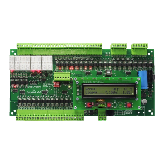
- Page 13 3. CONTENTS OF PAGES 3. CONTENTS OF PAGES DISPLAYED ON LCD DISPLAYED ON LCD 3. CONTENTS OF PAGES DISPLAYED ON LCD 3. CONTENTS OF PAGES DISPLAYED ON LCD Page 1 Company name, So ware version Time, date and day of the week Page 2 line: Elevator status ...
- Page 14 4. VIEWING FAULTS AND 4. VIEWING FAULTS AND FAULTS CODE DESCRIPTION FAULTS CODE DESCRIPTION 4. VIEWING ERRORS AND ERRORS DESCRIPTION . VIEWING ERRORS AND ERRORS DESCRIPTION 4.1 HOW TO VIEW THE ERRORS 4.1 HOW TO VIEW THE ERRORS Errors detected by the board are divided into three levels: Level I errors: errors that block the elevator when they occur.
-
Page 15: Down
4. VIEWING FAULTS AND 4. VIEWING FAULTS AND FAULTS CODE DESCRIPTION FAULTS CODE DESCRIPTION 4.3 ERROR CODE DESCRIPTION 4.3 ERROR CODE DESCRIPTION Error Message Error Descrip on Level Action taken - Waits for safety circuit to close. Calls are cancelled if fault Safety circuit and/or door opened during S yopnd in travl persists more than 5sec. - Page 16 4. VIEWING FAULTS AND 4. VIEWING FAULTS AND FAULTS CODE DESCRIPTION FAULTS CODE DESCRIPTION 4.4 FAULTS TRANSLATION 4.4 FAULTS TRANSLATION ENGLISH FRENCH SWEDISH ARABIC ﻓﺘﺢ اﻷﻤﺎن ﻓﻲ اﻟﺠوﻟﺔ S yopnd in travl Sec. ouv. enmarche S ybrutenifärd ﻓﺘﺢ اﻷﻤﺎن ﻓﻲ اﻟﺠوﻟﺔ S yopnd in travl Sec.
- Page 17 5. AUXILIARY 5. AUXILIARY FUNCTIONS FUNCTIONS MENU MENU 5. MENU 5. MENU 5.1 PASSWORD 5.1 PASSWORD A password is required for accessing the menu. The password consists of 6 digits. Two passwords can access the menu. The first is provided by S. & A.S. Co. Ltd. and is referred to as client password. This password can only be changed by S.
- Page 18 5. AUXILIARY 5. AUXILIARY FUNCTIONS FUNCTIONS MENU MENU 5.3 MENU DESCRIPTION 5.3 MENU DESCRIPTION What you see Visibility Default Normal Insp Descrip on and Comments Range Mode Mode on the display Condition Value V4.00.K Firmware version + revision number V Normal Li /Door Status + Floor number FLxx...
-
Page 19: Down
5. AUXILIARY 5. AUXILIARY FUNCTIONS FUNCTIONS MENU MENU What you see Visibility Default Normal Insp Descrip on and Comments Range Mode Mode on the display Condition Value When this feature is enabled, the motor PTC Detec on Disabled/Enabled Disabled PTC is con nuously monitored When this feature is enabled, the output Light Inverted Disabled/ Enabled... -
Page 20: Down
5. AUXILIARY 5. AUXILIARY FUNCTIONS FUNCTIONS MENU MENU What you see Visibility Default Normal Insp Descrip on and Comments Range Mode Mode on the display Condition Value When this feature is enabled, the door Permanent closing signal is permanently engaged Automa c door Disabled/Enabled Disabled... -
Page 21: Down
5. AUXILIARY 5. AUXILIARY FUNCTIONS FUNCTIONS MENU MENU What you see Visibility Default Normal Insp Descrip on and Comments Range Mode Mode on the display Condition Value AC 2speed / Hydraulic / Drive Selects the drive type AC 2speed VVVF Intermediat VVVF drive &... - Page 22 5. AUXILIARY 5. AUXILIARY FUNCTIONS FUNCTIONS MENU MENU What you see Visibility Default Normal Insp Descrip on and Comments Range Mode Mode on the display Condition Value Car Panel Lock Sets the 2nd locked floor and its Cabin Lock2 FL# Enabled &...
- Page 23 5. AUXILIARY 5. AUXILIARY FUNCTIONS FUNCTIONS MENU MENU What you see Visibility Default Normal Insp Descrip on and Comments Range Mode Mode on the display Condition Value Ini ates a trip to calculate the distance Calc. HiSpd traveled to accelerate from zero to high VVVF drive &...
- Page 24 5. AUXILIARY 5. AUXILIARY FUNCTIONS FUNCTIONS MENU MENU 5.3.1 MENU TRANSLATION INTO FRENCH AND ARABIC 5.3.1 MENU TRANSLATION INTO FRENCH AND ARABIC ENGLISH FRENCH SWEDISH ARABIC 3.00.H V3.00.H V3.00.H ط أ ﻋﺎدي Normal FLxx Normal Etxx )--=اظﻬﺎر اﻷﺨطﺎء )ﺤﺎﺴم View Faults (Fatal=--) VoirFautes (Fatal=--) رﺤﻠﺔ...
-
Page 25: Down
5. AUXILIARY 5. AUXILIARY FUNCTIONS FUNCTIONS MENU MENU ENGLISH FRENCH SWEDISH ARABIC اﻟﻌ ر ﺒﺔ ﻋﺎﻟﻘﺔ ﺒﻌد ﻤرور Car jammed delay Delaicabinebloquee Fördr.pga.överlast ﻋﻤﻠﯿﺔ ﺒﺎب أوﺘوﻤﺎﺘﯿك Auto Door Opera on Opera on porte auto. Autdörrstyrning اﻟﺴر ﻋﺔ ﺨﻼل اﻟﻔﺤص Inspec on speed Vitesse de Revision Inspek onshas ghet اﻨﺤدار... - Page 26 5. AUXILIARY 5. AUXILIARY FUNCTIONS FUNCTIONS MENU MENU ENGLISH FRENCH SWEDISH ARABIC ﻀﺒط اﻟﺘﺎ ر ﯿﺦ Adjust Date Ajuster La Date Ställ datum ﻀﺒط اﻟﯿوم Adjust Day Ajuster Le Jour Ställ dag ﺤﻔظ اﻟﻀﺒط ﻋﻠﻰ Upload se ngs to DT Enregistrerparam.sur DT Laddainst.
- Page 27 6. DIP SWITCHES FUNCTION DESCRIPTION 1 2 3 1 2 3 4 4 ON = Encoder is powered from MicroZed v3.5 Not used OFF = Hardware implementation of EOS DNI and EOS UPI is enabled, this mean whenever EOS DNI/EOS UPI opens when lift is going in the down/up direction, speed reference signals (High, Low, Intermediate) are immediately removed.
- Page 28 EOS UP1 and EOS DN1 must be installed at a distance of 1.5 m from last floor and first floor respectively. Encoder must be connected to MicroZed v3.5 controller. 7.2 SETTINGS IN THE MAIN MENU 7.2 SETTINGS IN THE MAIN MENU Set the “Drive”...
- Page 29 8. MANUAL 8. MANUAL FLOOR FLOOR ADJUSTMENT ADJUSTMENT 8. MANUAL FLOOR ADJUSTMENT 8. MANUAL FLOOR ADJUSTMENT Manual floor adjustment allows the installer to fine-tune the floor stopping position of the lift and should only be done after learning trip procedure and distance calculation. Normally, if all DZ flags (or magnets) are accurately positioned on the floor level, no additional floor tuning would be necessary.
- Page 30 9. ACCESS 9. ACCESS CONTROL CONTROL 9. ACCESS CONTROL 9. ACCESS CONTROL Access control (i.e. carcalls lock) feature is now available. This means that if a car call is locked, a correspond- ing passcode must be entered to register and service this car call. 9.1 LOCKED FLOORS PASSCODES AND LOCKED FLOORS 9.1 LOCKED FLOORS PASSCODES AND LOCKED FLOORS In the menu, go to the "Access Control"...
- Page 31 10. FIRMWARE 10. FIRMWARE UPGRADE UPGRADE 10. FIRMWARE UPGRADE 10. FIRMWARE UPGRADE 10.1 INSTALLING THE SAS DEVICE FIRMWARE UPGRADE SOFTWARE 10.1 INSTALLING THE SAS DEVICE FIRMWARE UPGRADE SOFTWARE In order to upgrade firmware on site, a CD will be provided by S. &A.S.Ltd & the below steps shall be followed: 1.
- Page 32 10. FIRMWARE 10. FIRMWARE UPGRADE UPGRADE Select “Search automatically for updates driver software”.
- Page 33 10. FIRMWARE 10. FIRMWARE UPGRADE UPGRADE Select install this driver software anyway. The Driver SETUP procedure will be done only once For Windows vista/Win7. So, the driver of any new SAS Device connected to the PC USB port will be installed automatically. 10.2.2 DRIVER SETUP FOR WINDOWS XP 10.2.2 DRIVER SETUP FOR WINDOWS XP Each time New SAS Device is plugged into the PC USB port, a “Found New Hardware Wizard”...
- Page 34 10. FIRMWARE 10. FIRMWARE UPGRADE UPGRADE The driver of the new SAS Device connected to the PC USB port will be installed automatically. 10.3 FIRMWARE UPGRADE PROCESS 10.3 FIRMWARE UPGRADE PROCESS Run “SAS_PTool” application. The following window will appear prompting the user that the SAS board is detected on the USB port: Click Open to choose the *.sas file that will be used to upgrade the firmware.
- Page 35 10. FIRMWARE 10. FIRMWARE UPGRADE UPGRADE The upgrade progress is shown as below: Once the upgrade is complete, the footnote “Firmware upgraded successfully” will appear: Then the SAS device firmware upgraded successfully, and the SAS device will automatically run the new firmware.
- Page 36 10. FIRMWARE 10. FIRMWARE UPGRADE UPGRADE 10.4. FIRMWARE UPGRADE USING GOOGLE PLAY STORE ON SMART PHONE 10.4. FIRMWARE UPGRADE USING GOOGLE PLAY STORE ON SMART PHONE 10.4.1 INSTALLING THE SASPTOOL FIRMWARE APPLICATION ON THE MOBILE 10.4.1 INSTALLING THE SASPTOOL FIRMWARE APPLICATION ON THE MOBILE In order to upgrade the firmware from your mobile, follow the below steps: 1.
- Page 37 10. FIRMWARE 10. FIRMWARE UPGRADE UPGRADE Power off the SAS board Use a USB cable to connect board to the mobile. Turn SAS device on. The following window will appear showing that a SAS Device is now connected: Click on the sas file that you need to download. POPUP POPUP window will appear showing the file name, its description and its date:...
- Page 38 10. FIRMWARE 10. FIRMWARE UPGRADE UPGRADE Once the download is completed, the message “Firmware downloaded successfully” will appear: Disconnect the USB cable. The user can now process with normal operation. If you desire to delete any sas file from the mobile list, press and hold on the filename until a POPUP POPUP window...
- Page 39 11. BOARD 11. BOARD DIMENSION DIMENSION 11. BOARD DIMENSION 11. BOARD DIMENSION 10.0 mm 291.0 mm 5.0 mm 4.0 mm 4.0 mm...
- Page 40 12. APPENDIX A 12. APPENDIX A 12. APPENDIX A 12. APPENDIX A This appendix contains all wiring diagrams relevant to assembling the board in a panel.
- Page 41 SOP1 HIGH CDRV +22V MICROZED V3.5 BOARD S.&A.S. Ltd. Note: Jieh Chouf Lebanon (*) FW V3.00.H and later support@sascontrollers.com MICROZED V3.5 HYDRAULIC WIRING DIAG: SUPPLY & OUTPUTS DC Contactors Size FCSM No. DWG No. A350HYDV1W1_Supply_ContDC.Sch Scale Sheet 1 of 16...
- Page 42 CDRV CLGT LGHT +22V MICROZED V3.5 BOARD S.&A.S. Ltd. Note: Jieh Chouf Lebanon (*) FW V3.00.H and later support@sascontrollers.com MICROZED V3.5 HYDRAULIC WIRING DIAG: SUPPLY & OUTPUTS AC Contactors Size FCSM No. DWG No. A350HYDV1W2_Supply_ContAC.Sch Scale Sheet 2 of 16...
- Page 43 STAR CDRV +22V MICROZED V3.5 BOARD S.&A.S. Ltd. Note: Jieh Chouf Lebanon (*) FW V3.00.H and later support@sascontrollers.com MICROZED V3.5 HYDRAULIC WIRING DIAG: SUPPLY & OUTPUTS - HYDRAULIC STAR/DELTA DC Contactors Size FCSM No. DWG No. A350HYDV1W3_Supply_STAR-DELTA_ContDC.Sch Scale Sheet 3 of 16...
- Page 44 STAR CDRV +22V MICROZED AR V3.1 BOARD S.&A.S. Ltd. Note: Jieh Chouf Lebanon (*) FW V3.00.H and later support@sascontrollers.com MICROZED V3.5 HYDRAULIC WIRING DIAG: SUPPLY & OUTPUTS - HYDRAULIC STAR/DELTA AC Contactors Size FCSM No. DWG No. A350HYDV1W4_Supply_STAR-DELTA_ContAC.Sch Scale Sheet...
- Page 45 MICROZED V3.5 BOARD S.&A.S. Ltd. Note: Jieh Chouf Lebanon (1): DZ is recomended for automatic support@sascontrollers.com door. MICROZED V3.5 HYDRAULIC WIRING DIAG: INPUTS/DOOR INFO (2): FW V3.00.H and later AC Contactors (*): "PP" only for magnetic switches Size FCSM No. DWG No.
- Page 46 AC MOTOR SUPPLY ACCORDING TO CAM VOLTAGE CDOOR CLSE CDOOR CLSE CLSE MICROZED V3.5 BOARD S.&A.S. Ltd. Jieh Chouf Lebanon support@sascontrollers.com MICROZED V3.5 HYDRAULIC WIRING DIAG: DOOR INFO DC Contactors Size FCSM No. DWG No. A350HYDV1W6_Ips_ContDC.Sch Scale Sheet 6 of 16...
- Page 47 SUPPLY ACCORDING TO 0Vac CAM VOLTAGE CDOOR CLSE CLSE CLSE CDOOR MICROZED V3.5 BOARD S.&A.S. Ltd. Jieh Chouf Lebanon support@sascontrollers.com DOOR INFO MICROZED V3.5 HYDRAULIC WIRING DIAG: AC Contactors Size FCSM No. DWG No. A350HYDV1W7_Ips_ContAC.Sch Scale Sheet 7 of 16...
- Page 48 MICROZED X BOARD #2 MICROZED V3.5 BOARD A MICROZED V3.5 BOARD B RS485 Data CAT5 Shielded Cable S.&A.S. Ltd. Jieh Chouf Lebanon support@sascontrollers.com MICROZED V3.5 HYDRAULIC WIRING DIAG: LANDING CALLS FOR DUPLEX ON EXTENSION Size FCSM No. DWG No. A350HYDV1W8_CALLS-Duplex.Sch Scale...
- Page 49 LAND CALLS DOWN LAND CALLS UP IF DUPLEX IF DUPLEX MICROZED V3.5 BOARD S.&A.S. Ltd. Jieh Chouf Lebanon support@sascontrollers.com MICROZED V3.5 HYDRAULIC WIRING DIAG: CALLS W/O EXTENSION FULL COLLECTIVE - 6 STOPS Size FCSM No. DWG No. A350HYDV1W9_CALLS-Full6.Sch Scale Sheet...
- Page 50 CAR CALLS LAND CALLS DOWN IF DUPLEX MICROZED V3.5 BOARD S.&A.S. Ltd. Jieh Chouf Lebanon support@sascontrollers.com MICROZED V3.5 HYDRAULIC WIRING DIAG: CALLS W/O EXTENSION DOWN COLLECTIVE - 8 STOPS Size FCSM No. DWG No. A350HYDV1W10_CALLS-Dn8.Sch Scale Sheet 10 of 16...
- Page 51 IF DUPLEX CT CT EC EC MICROZED X BOARD MICROZED V3.5 BOARD S.&A.S. Ltd. Jieh Chouf Lebanon support@sascontrollers.com MICROZED V3.5 HYDRAULIC WIRING DIAG: CALLS WITH 1 EXTENSION FULL COLLECTIVE - 11 STOPS Size FCSM No. DWG No. A350HYDV1W11_CALLS-Full11_With1Ext.Sch Scale Sheet...
- Page 52 IF DUPLEX OR MICROZED X BOARD #1 MICROZED V3.5 BOARD S.&A.S. Ltd. Jieh Chouf Lebanon support@sascontrollers.com MICROZED V3.5 HYDRAULIC WIRING DIAG: CALLS WITH 1 EXTENSION DOWN COLLECTIVE - 16 STOPS Size FCSM No. DWG No. A350HYDV1W12_CALLS-Dn16_With1Ext.Sch Scale Sheet 12 of 16...
- Page 53 IF DUPLEX OR MICROZED X BOARD #1 MICROZED V3.5 BOARD IF DUPLEX S.&A.S. Ltd. Jieh Chouf Lebanon support@sascontrollers.com MICROZED V3.5 HYDRAULIC WIRING DIAG: CALLS WITH 2 EXTENSIONS DOWN COLLECTIVE- 16 STOPS MICROZED X BOARD #2 Size FCSM No. DWG No. A350HYDV1W13_CALLS-Dn16_With2Ext.Sch...
- Page 54 MICROZED V3.5 BOARD IF DUPLEX OR MICROZED X BOARD #2 MICROZED X BOARD #3 S.&A.S. Ltd. Jieh Chouf Lebanon support@sascontrollers.com MICROZED V3.5 HYDRAULIC WIRING DIAG: CALLS WITH 3 EXTENSIONS DOWN COLLECTIVE- 16 STOPS Size FCSM No. DWG No. A350HYDV1W14_CALLS-Dn16_With3Ext .Sch Scale...
- Page 55 CT0 CT1 CT15 MICROZED V3.5 BOARD S.&A.S. Ltd. INDICATR="ENHANCED" or Jieh Chouf "7SEGMENT" Lebanon support@sascontrollers.com CALLS - COLLECTIVE MULT COLLECTV="DOWN" MICROZED V3.5 HYDRAULIC WIRING DIAG: DOWN - 16 STOPS Size FCSM No. DWG No. A350HYDV1W15_CALLS-COLLECTIVE_MULT_Dn16.Sch Scale Sheet 15 of 16...
- Page 56 HALL - CT0 CT1 CT15 MICROZED V3.5 BOARD S.&A.S. Ltd. Jieh Chouf Lebanon support@sascontrollers.com CALLS - COLLECTIVE MULT MICROZED V3.5 HYDRAULIC WIRING DIAG: FULL- 9 stops Size FCSM No. DWG No. A350HYDV1W16_CALLS-COLLECTIVE_MULT_Full16.Sch Scale Sheet 16 of 16...
- Page 57 WHICH ELEVATO OR CONT ROLLER IS RIGH HT FOR Y YOU? MicroZed v3 3.3a MicroZed v3.5a MicroZed-A A v3.1 MicroZed-AR v3. ASTR RA v1.2 C 1 speed C 2 speed ...
- Page 58 MicroZed v3 3.3a M M icroZed v3.5a MicroZed-A A v3.1 MicroZed-AR v3.1 ASTR R A v1.2 nary Code ndicator Enha anced Code ndicator cimal code — — ndicator Contactors ...
- Page 59 MicroZed v3 3.3a M M icroZed v3.5a MicroZed-A A v3.1 MicroZed-AR v3.1 ASTR R A v1.2 Grap hical Display — — 24-Cha arx2-lines LCD — — — alphan umeric display Diag gnostic Tool — — —...
Need help?
Do you have a question about the MicroZed V3.5 and is the answer not in the manual?
Questions and answers