Table of Contents
Advertisement
Quick Links
Advertisement
Table of Contents
Troubleshooting

Summary of Contents for Actelis Networks ML700
- Page 1 User Manual ML700 Release 7.14 Revision No. A04 Document No. 520R70714E...
- Page 3 Further, in no event, shall Actelis Networks be liable for incidental or consequential damages in connection with or arising from the use of the ML700 series, cards and modules, accessories kits, this manual or any related materials. Actelis Networks reserves the right to revise this publication from time to time and to make changes in the content hereof without obligation to notify any person of such revisions or changes.
- Page 4 Preface Document Objectives This manual provides a general description of the ML700 device, detailed instructions for the deployment and maintenance of the ML700 device. Intended Audience The intended audience for this document is both technical and non-technical staff within Network Service Provider (NSP) organizations, and it is assumed that the reader has a general understanding of voice and data communications, the xDSL industry and high-speed digital services.
-
Page 5: Ml700 Certification
ML700 Certification FCC Class A Compliance The ML700 complies with the limits for a Class A digital device that is marketed for use in a commercial, industrial or business environment, exclusive of a device which is intended to be used by the general public or is intended to be used in the home. This equipment generates, uses, and can radiate radio-frequency energy and, if not installed and used in accordance with the Quick Installation Guide, may cause harmful interference to radio communications. - Page 6 Preface Canadian Emissions Requirements The ML700 Class A digital apparatus meets all requirements of the Canadian Interference- Causing Equipment Regulations. Cet appareil numérique de la classe A respecte toutes les exigences du Règlement sur le matériel brouilleur du Canada. Warning: This is a Class A product. In a domestic environment, this product may cause radio interference, in which case you may be required to take adequate measures.
-
Page 7: General Safety Summary
10. Many of the cables for this product are supplied by Actelis Networks. Cables that are supplied by the customer must comply with the regulatory inspection authorities and are the responsibility of the customer. -
Page 8: Résumé Des Conditions Générales De Sécurité
évaluations. 10. De nombreux câbles de ce produit sont fournis par la société Actelis Networks. Les câbles qui sont fournis par le client doivent adhérer aux normes des autorités d'inspection et relèvent de la responsabilité... - Page 9 Aussi, ne jamais regarder directement la fibre port TX et le câble de fibre se termine quand ils sont sous tension. 17. Dans le cas d'une alarme FAN, vous devez remplacer le ML700 dans les 4 heures qui suivent. Prévention des décharges électrostatiques (ESD) Dommages 1.
-
Page 10: Allgemeine Sicherheitshinweise
Sicherungen verwenden. Bevor Sie Anschlüsse an die Switche durchführen, bitte sorgfältig die Hinweise in den Benutzerhandbüchern durchlesen. 10. Viele der an die Switche angeschlossenen Kabel, werden von Actelis Networks geliefert. Kabel welche nicht von Actelis Networks geliefert werden, müßen den sonstigen Sicherheitsvorschriften entsprechen. - Page 11 Rates der Europäischen Union über Elektro- und Elektronik-Altgeräte (WEEE). Es wurde unter Anwendung der Direktive nach dem 13. August 2005 auf den Markt gebracht und sollte nicht als Haushaltsmüll entsorgt werden. Bitte nutzen Sie Ihre lokale WEEE-Sammelstelle für die Entsorgung des Produkts und beachten Sie auch alle sonstigen Vorschriften. ML700 User Manual...
-
Page 13: Table Of Contents
ML700 Models ............................1-3 ML700 Architecture ..........................1-4 ML700 Topologies ........................... 1-5 Management ............................. 1-7 ML700 Front and Rear Panel Descriptions ....................1-8 ML700 Front Panel Description ....................1-8 ML700 Rear Panel Description ..................... 1-9 ML700 link with BBA units ........................1-11 ML700 and BBA installation ...................... -
Page 14: Contents
IGMP Bridge Level Configuration ....................5-15 Static Multicast IP Configuration ....................5-16 IP Multicast Monitoring ......................5-18 STP/RSTP and Provider Bridge Configuration ..................5-20 STP/RSTP Configuration Principles ................... 5-21 The STP Workspace ........................5-22 STP/RSTP Bridge Configuration ....................5-23 User Manual ML700... - Page 15 Membership Rules ........................8-12 9 L2CP Processing Supported L2CP Protocols ........................9-2 Configuring Handling of L2CP Frames ....................9-3 Deployment Considerations ........................9-6 Case 1 ............................9-6 Case-2 ............................9-7 Case 3A ............................9-8 Case 3B ............................9-8 ML700 User Manual XIII...
- Page 16 RADIUS Message Parameters Supported by ML ..............12-18 RADIUS Service Type Parameters Supported by ML .............. 12-19 Radius Server Configuration for ML Versions ................12-20 IP Access Control List (ACL)....................... 12-21 Managing the IP Access Control List (ACL) ................12-21 User Manual ML700...
- Page 17 Loop Diagnostic Tools ......................13-52 14 Administration 14-1 Using MetaASSIST View ........................14-2 Configuration Backup and Restore ....................14-2 Log Files Management ........................ 14-5 ML Software Control......................... 14-13 File Restore ..........................14-18 Restarting the ML NE........................ 14-19 ML700 User Manual...
- Page 18 Login problems (common for all interfaces) ................15-27 Resolving MetaASSIST View / Actelis System Software Problems......... 15-28 Resolving Management Connection Problems ..................15-29 Configuration Problems ......................15-29 Login problems (common for all interfaces) ................15-32 Resolving MetaASSIST View / Actelis System Software Problems......... 15-33 User Manual ML700...
- Page 19 Contents Appendix A - Technical Specifications ML700 Specifications ........................... 2 ML700 Supported SNMP MIBs ........................5 Customer Logs .............................. 6 Appendix B - Parts List SFP Modules ..............................2 Cables ................................4 Accessories ..............................6 Appendix C - Step-by-Step Commissioning Procedures CO Site Installation ............................
- Page 20 Contents Appendix H - Environmental Alarm Condition Types Appendix I - Recommended Actelis MiTOP Configuration Parameters MiTOP System Parameters ........................... 2 MiTOP Physical Layer Parameters ....................... 5 MiTOP Applications Parameters ........................6 XVIII User Manual ML700...
-
Page 21: Introduction
Introduction This chapter introduces ML700 Actelis devices, the basic architecture and the most common topologies in which ML700 devices can be installed. The descriptions differentiate between various types of ML700 product models. ML700 User Manual... -
Page 22: About Ml700
ML 600 product line, through offering a cost-effective delivery of Ethernet in the First Mile (EFM) high-speed Carrier Ethernet services over the existing copper infrastructure. The ML700 is designed for point-to-point topologies as well as a CPE only product, working with approved 3... -
Page 23: Ml700 Models
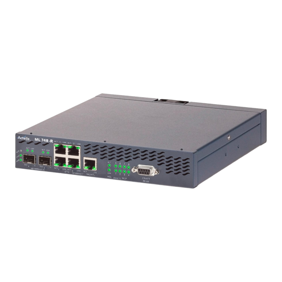
ML700 Models Introduction ML700 Models A range of ML700 models are available for special implementations. The models are either CO (-O) or CPE (-R) specific units and support either 2, 4 or 8 DSL ports. The full Appendix A – Technical... -
Page 24: Ml700 Architecture
Introduction ML700 Architecture ML700 Architecture This section describes the general architecture of ML700 family of products. ML700 architecture consists of the following main functional blocks: Ethernet Bridge and Control – supports Ethernet (ETH-x) and Ethernet-like (HSL-1) Service ports, provides 802.1Q VLAN-aware bridging between these ports, system control and management functionalities. -
Page 25: Ml700 Topologies
ML700 Topologies Introduction ML700 Topologies ML700 systems support the following topologies: Point to Point Topology, with and without BBA link accelerators CPE only for third party CO unit ML700 Applications: Backhauling for Remote (IP) DSLAM Backhauling for Cellular Base Station ... - Page 26 Introduction ML700 Topologies Figure 5: Mix of Applications Figure 6: Business Ethernet Services with 3 party DSLAM CO unit User Manual ML700...
-
Page 27: Management
Actelis systems on the entire network. MetaASSIST EMS consists of MetaASSIST EMS server and MetaASSIST EMS client and requires the MetaASSIST View application. To obtain these software applications and the MetaASSIST EMS Online Help contact your local Actelis Networks sales representative, service representative or distributor. ... -
Page 28: Ml700 Front And Rear Panel Descriptions
ML700 Front and Rear Panel Descriptions This section describes the ML700 front and rear panel connections and LEDs. ML700 Front Panel Description ML700 front panel contains the Ethernet service ports and the management connection ports. The following example shows the ML700 interfaces. Note the following: ... -
Page 29: Ml700 Rear Panel Description
Indicate status of the copper-pair ports located on the device rear panel. Each LED indicates the synchronization status of corresponding modem. ML700 Rear Panel Description The ML700 rear panel contains the copper-pair connections, power, alarms and reset switch. Figure 8: Rear Panel of ML-700 Model ML700 User Manual... - Page 30 Power requirement: -48 VDC nominal (-40 to -60 VDC max), 2 Amperes maximum (17W maximum for ML740). Units’ main Grounding. GND1 GND2 Grounding option for a floating AC/DC converter, refer to ML700 Quick Installation Guide document for details. 1-10 User Manual ML700...
-
Page 31: Ml700 Link With Bba Units
(distance from CO unit and BBA), spectral regulations and environmental noise. ML700 and BBA installation BBA unit is line power fed from the ML700-O unit, no option for local power feeding. Contact Actelis’ customer support for Express powered BBA roadmap. Links’ performance with BBA depends on loop topology and available location for BBA placement. -
Page 33: Getting Started
Getting Started This chapter provides information on how to connect to and navigate the MetaASSIST View. In This Chapter Commissioning Procedure ........... 2-2 Craft Connection to the ML .......... 2-3 MetaASSIST View Workplace ........2-6 ML700 User Manual... -
Page 34: Commissioning Procedure
The CRAFT port setting on the management host/computer should match the ML device. Initially (after factory setup) all ML devices accept 9600 bps baud rate. Appendix C with Step-by-Step Commissioning procedure (on page C-1) User Manual ML700... -
Page 35: Craft Connection To The Ml
2. Launch the MetaASSIST application by doing one of the following: Click the MetaASSIST View icon on the Desktop, or From the Start menu, select Programs> Actelis Networks>MetaASSIST View. The MetaASSIST Main window opens and the Connect dialog is automatically invoked. ML700 User Manual... - Page 36 Configure and set the baud-rate in the dialog to match your computer. 4. Determine how sessions will be available to the hosted CPEs displayed under the CO: Auto Login to CPE enabled - default setting. All the hosted CPEs will be accessible. User Manual ML700...
- Page 37 NOTE: User Name and Password are case sensitive. Change passwords according to Password Control (on page 12-8). 7. To save parameters for the next login, checkmark Save Parameters. 8. Click OK. A new session is opened to the NE. The MetaASSIST View Main window appears. ML700 User Manual...
-
Page 38: Metaassist View Workplace
MetaASSIST View Main window shows directly connected ML device and all auto-discovered indirectly (via HSL) connected ML devices. View areas are adjustable. Where applicable, panes with tables have a multiple selection feature allowing you to click- and-drag to select multiple rows. User Manual ML700... -
Page 39: Menu Bar
Generate SSH Client Key - used to generate new keys for secure connection with ML device (SSHv2) with or without a passphrase NE List Control - used to maintain updated list of NEs to which sessions have been opened. Exit - closes the application. ML700 User Manual... - Page 40 time to the selected NEs. Help. Provides help and MetaASSIST View version information. Actelis Systems Online Help - contains full user manual with advanced search capabilities. About MetaASSIST View - MetaASSIST View version information. User Manual ML700...
-
Page 41: Physical Tab
Network Element (NE) to which a session was opened. If the NE is a CO, this tab also provides access to the hosted CPE. The NE tab space is divided to Topology Tree and NE Navigation Tree. ML700 User Manual... - Page 42 Displays IP address when available and indicates full management access. In most cases, all HSL linked NEs along with the corresponding TID and IP are automatically added during connection. For other cases, see Logging In descriptions. 2-10 User Manual ML700...
- Page 43 IP address availability - SNMP agent is unavailable for NEs without an IP address. Figure 9: Navigation tree area The following table describes the icons in the Navigation tree. These also appear in the work area and system alarms table. ML700 User Manual 2-11...
- Page 44 The Network Element pane provides a glance view of local Network Element and when applicable, Network Element linked via HSL. To access the Network Element pane In the Network Element tree, click Network Element. The Network Element pane opens in the work area. 2-12 User Manual ML700...
-
Page 45: Connectivity Tab
Connectivity Tab The Connectivity tab provides several options, available as main tree items: NOTE: The available options may vary depending on your ML700 model. Ethernet Connection - used to monitor status and setup of the particular Ethernet Connection (predefined via the Physical tab). -
Page 46: Current Alarms Area
(German), ñ (Spanish), å (Swedish and other Nordic languages) and Ö(Hungarian). NOTE: MetaASSIST View and MetaASSIST EMS ignore the following: ? (0x3F ASCII code), " (0x22 ASCII code) and /n line feed (0x0A ASCII code) characters. 2-14 User Manual ML700... - Page 47 IP/LAN Connectivity on Directly Connected NE ..3-11 IP/LAN Connectivity on Indirectly Connected NE ..3-12 L2 (MGMT VLAN) Connectivity ........3-14 L3 (IP) Connectivity ............ 3-14 SNMP Agent and Trap Parameters ......3-15 System Name Configuration ........3-20 Date and Time Setting..........3-21 ML700 User Manual...
-
Page 48: Management Configuration
The peer NE (either CO or CPE) has “Access from Peer” Enabled (factory setup) – controls IP-less access (via craft port). Note: A MAV Craft port session shows CO NE linked via HSL only in P2P topology of ML700 and ML600 models (except for ML688). User Manual ML700... - Page 49 IP/Ethernet connection - requires configuration of IP Address, Gateway and Subnet Mask configured on the NE. The MGMT VLAN must be consistently configured on all NEs. Note: The IP/Ethernet access on each NE can be controlled and additionally secured (by ACL or SSH). ML700 User Manual...
-
Page 50: Opening A Metaassist View Session
Ethernet service port - by default, it is configured for service traffic only. Can also be configured for in-band management. HSL port. Enables indirect access to remote ML systems from the directly connected system. By factory default, all HSL ports are included in default MGMT VLAN (VID=100) as tagged members. User Manual ML700... -
Page 51: Tcp/Ip Connection To The Ml
1. Launch the MetaASSIST application by doing one of the following: Click the MetaASSIST View icon on the Desktop, or From the Start menu, select Programs> Actelis Networks>MetaASSIST View. The MetaASSIST Main window opens and the Connect dialog is automatically invoked. ML700 User Manual... - Page 52 CPE of interest and selecting Auto-connect. NOTE: If Save Parameters is enabled, the Auto-login settings are saved. 5. LLDP - this option is relevant to ERPS. In order to configure ERPS (at a later phase), it is required to enable LLDP. User Manual ML700...
-
Page 53: Auto-Discovery Of Ml Systems
Each time the MetaASSIST application is invoked, the Connect dialog appears. In addition to the standard Craft and TCP/IP connectivity options, the dialog provides access to Auto- discovery options. 1. In the Connect dialog box, click the Search button. ML700 User Manual... -
Page 54: Units That Failed To Connect
To view the device that failed to auto-connect or login and troubleshoot the connection 1. In the Network Element Tree: Click Network Elements Linked via HSL and then ML failed to auto-connect and/or login or Click on the corresponding link on the Network Elements Linked via HSL pane User Manual ML700... - Page 55 Accesses the L2/L3 setting configuration options. Used to change IP, subnet mask, Gateway configuration mismatch or MGMT VLAN configuration mismatch. Configure VLANs Accesses the VLAN configurations options of the selected device. For more (link) details about this procedure, see VLAN Configuration (on page 8-1). ML700 User Manual...
-
Page 56: Ip-Less Connection To Ml (Cpe)
NE Linked via ETH view is disabled on non-IP CPE. CPE NEs support full TL1/MAV capabilities (including file transfer-based features) on non-IP CPEs. CPE NEs supports SNMP trap forwarding from non-IP CPE through IP-based CO. 3-10 User Manual ML700... -
Page 57: Ip/Lan Connectivity On Directly Connected Ne
To provide IP/LAN connectivity on a locally connected NE, you will need the Management VLAN, IP address, IP gateway address, and IP subnet mask information from your Network Administrator for each NE installed in the topology. ML700 User Manual 3-11... -
Page 58: Ip/Lan Connectivity On Indirectly Connected Ne
The peer NE (either CO or CPE) has "Access from Peer" Enabled (factory setup). When opening a local (craft connection) MetaASSIST View session to an ML700 CPE in a P2P topology, the CO NE linked via HSL is displayed as well. - Page 59 Set as local - Read only - sets the LAN parameters to the same values as those of the host CO. Set manually - initially displays the configuration of the remote NE. The parameters can be modified. Click OK. ML700 User Manual 3-13...
-
Page 60: L2 (Mgmt Vlan) Connectivity
Management Configuration L2 (MGMT VLAN) Connectivity L2 (MGMT VLAN) Connectivity ML700 provides Management LAN access according to 802.1Q bridge mode (VLAN aware) - accessible via COLAN (MGMT) for untagged management traffic. L3 (IP) Connectivity ML systems are assigned the default IP address and Gateway of 0.0.0.0 (unusable) and a Subnet Mask of 255.255.0.0 (Class IP Addresses). -
Page 61: Snmp Agent And Trap Parameters
In the invoked pane, Configuration area, click Configure. The SNMP Settings pane opens. NOTE: To invoke the dialog for a selected Group: in the Network Topology tree select the Group item, in the Menu bar, select Group Operations, SNMP Configure. The SNMP Settings pane opens. ML700 User Manual 3-15... -
Page 62: Snmp Trap Destinations
2. Open SNMP. The SNMP Settings pane opens. 3. Click the Add button. The Add SNMP Trap Destination dialog appears. NOTE: For group operations, open the Add SNMP Trap Destination dialog box via the menu bar: Group Operations, SNMP, Add. 3-16 User Manual ML700... - Page 63 The SNMP version defines the structure of the traps that will be sent to the SNMP management system. 7. In the Port box, type the SNMP/UDP trap notification port of OSS/NMS host where the ML device traps are to be received. Click OK. ML700 User Manual 3-17...
-
Page 64: Snmp Trap Filtering
Traps/Notifications either by ACTELIS ENTERPRISE OID or by OID of the STANDARD MIB where these Traps/Notifications are defined. NOTE: Irrelevant for ML700 DMT model traps (from SHDSL-MIB and EFM-CU-MIB) are grayed- out as unsupported. To filter out SNMP traps for a selected ML system 1. -
Page 65: Snmp Traps From Non-Ip Cpes
Optionally, enable Bridge MIBs and click OK. SNMP Traps from Non-IP CPEs ML700 CPE that is not assigned an IP (hosted by an IP-based CO NE) sends SNMP notifications using the IP address of the host CO NE. All configurations of SNMP Agent/Trap Destination provided on non-IP NE are used by the ML to originate the trap, although CO NE IP address is attached when trap frame is sent to the Management plane thought CO NE. -
Page 66: System Name Configuration
4. To assign the logical name to the system in SNMP, enable Apply to SNMP System Name. Unless this box is enabled, the SNMP System Name will be displayed as the serial number. 5. Click OK. 3-20 User Manual ML700... -
Page 67: Date And Time Setting
7. To set the time zone from the Time Zone list box, select the time zone in accordance to the local time zone (for example, GMT +4:00). NOTE: Time Zone is effective in Auto Sync mode only. 8. Click OK. ML700 User Manual 3-21... -
Page 68: Automatic Date And Time Adjustment
8. In Unicast mode only, in the Server IP Address box, type in the server IP address (default value on factory setup is 0.0.0.0). 9. Click OK. 10. To verify setting the Time Zone, see Configuring Date and Time Manually (on page 3- 21). 3-22 User Manual ML700... -
Page 69: Daylight Saving Time (Dst) Configuration
5. From the Start Day list boxes select the Start Day parameters. 6. From the End Day list boxes select the End Day parameters. NOTE: Start Day month and End Day month must be different. 7. Click OK. NOTE: Daylight Bias of 1 hour is not configurable. ML700 User Manual 3-23... -
Page 71: Equipment And Port Configuration
In This Chapter System-wide Settings ........... 4-2 Alarms and Indications Control ........4-5 SFP Pluggable Modules ..........4-8 Modem Line Ports (MLP) ........... 4-14 High Speed Link (HSL)..........4-17 Ethernet Port .............. 4-25 Static Link Aggregation (LAG) ........4-39 ML700 User Manual... -
Page 72: System-Wide Settings
System pane. To access the System pane In the Network Element tree, click System. The System pane opens in the work area. The pane is divided into three areas: Configuration, Alarms and Conditions and Details. User Manual ML700... -
Page 73: System Configurable Attributes
Manual - the identified external module is not enabled automatically. In order to be monitored, enable the SFP according to SFP Module Manual Control. 4. Set the Output Relays (on page 4-5) according to the installation: External Controls or Office Alarms. ML700 User Manual... - Page 74 All other Alarms (less critical or port alarms) are indicated by the port LED (available per ETH, HSL and MLP ports). In addition, alarms suppressed due to Partial alarm LED configuration are not reported via GPO as well. 7. Click OK. User Manual ML700...
-
Page 75: Alarms And Indications Control
Major or Critical alarm raised on the ML device will also activate the Audible office alarm. Office Alarm will Close due to: Unit initialization Critical or Major failure NOTE: Alarms suppressed due to Partial alarm LED configuration are not reported via GPO. ML700 User Manual... - Page 76 3. Select a row in the table and click Operate. The relay contact closes and "yes" appears in the Operated column. 4. To release the contacts, click Release. The Operated column is cleared and the relay contact opens. 5. Click OK. User Manual ML700...
-
Page 77: Environmental Alarm (Gpi) Configuration
Environmental Alarm Condition Types (on page 1) for details). From the Alarm Severity list box, select the required alarm severity. In the Alarm Description box, type a short description of the alarm. Click OK. ML700 User Manual... -
Page 78: Sfp Pluggable Modules
In the Network Element tree, select one of the following (depending on your system: For ML230/2300 - select Cards and Modules, SDU-x, SFP-x For all other units (ML500, ML600, ML700, etc.) - select Modules, SFP-x User Manual ML700... - Page 79 (in raised).ML integrates a single DDMALERT alarm raised over all possible (10) threshold cross events which may be reported by SFP. Note that SFP alarm thresholds are provided by the manufacturer and cannot be modified via the ML. ML700 User Manual...
-
Page 80: Mitop, Miric And Mirici Sfp Management Access
CBS: 60,000 kbps for T3; 45,000 kbps for E3. NOTE: In case the payload size is lower than the MiTOP default value of 256 bytes (not recommended), CBS value may need to be increased. EBS: 100,000 EIR=100 EBS=1632 4-10 User Manual ML700... - Page 81 MGMT VLAN (to separate the configuration and service data on the SFP) and apply COS=7 to MGMT traffic – to prioritize management above service. NOTE: For connection to the SFP plugged into the CPE NE, configure the SFP in the same Management plane as ML devices. ML700 User Manual 4-11...
- Page 82 Peer IP address - 10.1.50.2 - address of MiTOP-2 Optionally set MAC (usually discovered automatically by ARP) Attention! If you need to edit any parameter, you must fill all parameters in a table, because clicking the Save copies values from the table. 4-12 User Manual ML700...
- Page 83 Service Parameters - set Payload size and Jitter buffer (change default value of 500uSec to 2000uSec). Return and Save Set Connection Status Enable and Save In Monitoring you can see: Alarms (in Status), E3/T3 and Ethernet statistics, Connection status and statistics. ML700 User Manual 4-13...
-
Page 84: Modem Line Ports (Mlp)
View Spectral Details (on page 13-51) - provides detailed spectral information. Details (on page 13-45) - shows detailed information on the selected MLPs Configure Alarms (on page 13-10) - alarm configuration for the selected MLPs 4-14 User Manual ML700... - Page 85 MLP configuration (Configure button) and analysis options. Details - provides MLP control and analysis options. The View Line Inventory button displays hardware and software versions as well as various identification information. The remaining buttons are described following the image. ML700 User Manual 4-15...
-
Page 86: Mlp Configuration
Status (Tx mode, EWL length, etc.), Spectral details (US0 Mask, 13-51) US PSD, etc.) and US/DS signal power (dBm) measurements Line Inventory Available only on the ML700 CO. HW, SW, identification and status information on the CPE side of this copper pair. Quality Details (on page... -
Page 87: High Speed Link (Hsl)
High Speed Link (HSL) ML HSL is a logical port consisting of bonded, multiple MLPs that are allocated to that HSL. The HSL links an ML700 CO and an ML CPE unit. The HSL is then calibrated according to predefined calibration profile templates (on page 6-1). - Page 88 View Templates (on page 6-3) - link to DMT template management pane. Modem Details (on page 13-45) - tabular list of modems allocated to HSL and their details o HSL Details - detailed information on specific HSL 4-18 User Manual ML700...
- Page 89 HSL Connection pane (on page 13-46) (under Connectivity Tab) - shows details on both sides of the connection. It can be used to compare parameters of the CO versus the CPE HSL/MLP, debug mismatches, and more. ML700 User Manual 4-19...
-
Page 90: Hsl Configuration
High Speed Link (HSL) HSL Configuration No configuration is required for the ML700 HSL operation. However, you may optionally configure the Low Bandwidth threshold (for upstream and downstream) and some identification parameters. These serve to further optimize the link operation and determine how the calibration procedure is performed. - Page 91 To enter the current configuration into the configuration template checkmark the Save configuration to HSL template button. NOTE: The HSL Configuration file also stores the HSL calibration parameters. Usage of this file is also accessed through the HSL calibration pane. 9. Click OK. ML700 User Manual 4-21...
-
Page 92: Hsl Calibration
Regarding the Calibration process: modems that provide the optimal performance. HSL calibration invoked on ML700-O will begin when any one of the assigned to the HSL modems becomes available. Modems which are limiting the HSL performance will be automatically removed... - Page 93 Verify that In the HSL pane, Details area, view the Calib. Status parameter to determine the last operation applied on the HSL. Verify that the required profiles (Rate, SNR, etc.) and Template are updated. 3. In the Details area, click Calibrate. The Calibration dialog is invoked. ML700 User Manual 4-23...
- Page 94 The tab will be highlighted and displayed (Rate Profile in the example above). NOTE: If any parameter requires updating, update the specific profile first (see Modem Profiles Management Model (on page 6-1)) and only then update the template (if required). 7. Click OK. 4-24 User Manual ML700...
-
Page 95: Ethernet Port
COLAN (MGMT) Ethernet port for service purposes, see Traffic VLAN Procedure. In addition, port priority and pinout must be changed according to your setup. To dedicate the COLAN (MGMT) Ethernet port for management purposes, see Management VLAN Procedure (on page 8-3). ML700 User Manual 4-25... -
Page 96: Ethernet Port Workspace
Ethernet Glance View - lists all the Ethernet ports and their attributes in tabular format. In addition, the pane allows performing GROUP operations by selecting a number of Ethernet ports on which the desired configuration or control operations will be performed. Table 14: ML700 Workspace Button Description Reset all Statistics... - Page 97 Shows the bridge mode (e.g. 802.1Q) and PVID if relevant. Rate Limit / QoS Shows the Ingress and Egress rate limits and speeds for the port, as well as other QoS parameters such as Classification, Scheduler, etc. ML700 User Manual 4-27...
-
Page 98: Ethernet Port Configuration
2. In the Configuration area, click the Configure button. The Configure Ethernet Port dialog box appears. The example below shows the service Ethernet port dialog. However, other dialogs are similar in appearance, where irrelevant options are disabled. 4-28 User Manual ML700... - Page 99 Equipment and Port Configuration 3. Set the Physical interface ( IEEE 802.3 Ethernet media) (on page 4-30) parameter group. 4. Set the Link Loss Carrier Forward (LLCF) by Port(s) or/and MEP(s) triggers page 4-35) parameter group. ML700 User Manual 4-29...
- Page 100 Refer to Configuring Ethernet Ports for an overview. To configure the Ethernet port 802.3ah Physical Media parameters 1. Access the Ethernet Port Configuration dialog (partial dialog showing the parameters covered in this section is displayed below). 4-30 User Manual ML700...
- Page 101 Flow Control can be established as a part of Auto-negotiation or can be set manually. NOTE: In manual setting it is important that both ports are configured in the same way and in the same MODE, as the Flow control applied in HALF-DUPLEX and in FULL- DUPLEX modes are incompatible. ML700 User Manual 4-31...
-
Page 102: Llcf On Ml Devices
LLCF, where MEP triggered LLCF is supported only on Ethernet Service ports. The LLCF options are configured via the Ethernet Port Configuration dialogs. This section provides information on LLCF operation in ML700 and describes how to configure the LLCF functionality. - Page 103 NOTE: CO NE HSL can be optionally configured to monitor available HSL BW and report LLCF notification upon configurable threshold crosses down. The following figures illustrate end-to-end downstream LLCF notification for four types of failures: HSL down, low bandwidth on the HSL, CO Ethernet port down and CPE port down. ML700 User Manual 4-33...
- Page 104 Equipment and Port Configuration Ethernet Port 4-34 User Manual ML700...
- Page 105 Ethernet Port Equipment and Port Configuration Upstream LLCF in ML700 For UPSTREAM link monitoring (useful in P2P topologies): CO NE ETH port(s) - should be configured to monitor local HSL port as an LLCF trigger - this allows to monitor HSL port physical failure.
- Page 106 Equipment and Port Configuration Ethernet Port For more information on LLCF, refer to LLCF in ML700 Devices (on page 4-32). To define the Local Target LLCF Triggers 1. In the Network Element tree, select Ethernet Ports and choose the Ethernet HSL port that will be enabled for LLCF.
- Page 107 LLCF target port will forward the event (by message or disconnect) only if all enabled ports listed as trigger will fail. If any one of the failed ports in the LLCF Trigger List is up again, the LLCF target port will forward the event (by message or recovery). ML700 User Manual 4-37...
- Page 108 , LLCF will be applied when all (AND condition between LLCF Trigger Ports) listed ports have a failure condition OR at least one (OR condition between LLCF Trigger MEPs) listed MEP have a failure condition. 4-38 User Manual ML700...
-
Page 109: Static Link Aggregation (Lag)
The following buttons are available: Configure (on page 4-42) - displays the LAG port configuration dialog. Statistics - used to view Tx and Rx statistics of selected LAG ML700 User Manual 4-39... - Page 110 Glance View above, the pane contains the following areas: Configuration - shows the current parameter definitions and provides access to the LAG port configuration (Configure button) options. the Suspend button is used to stop the LAG port operation. 4-40 User Manual ML700...
-
Page 111: Overview Of The Lag Configuration Procedure
(LAG member) and switch over to another port (LAG member). Ingress/Egress Rate limiting is supported per port (in the LAG). A LAG takes on the VLAN definitions of the first port assigned to the LAG. ML700 User Manual 4-41... -
Page 112: Enabling And Configuring Lags
Mode - the speed supported by the LAG, and LLCF - Link Loss Carry Forward. . 4. The ML operates according to the Load Balancing Policy - MAC Source and Destination. In this policy, packets are matched with given MAC source and destination addresses. 5. Allocate Ethernet ports to the LAG. 4-42 User Manual ML700... -
Page 113: Allocating Ethernet Ports To Lags
2. For (traffic or management) VLAN configuration for a LAG: Configure ONE of the ports of the LAG according to VLANs (on page 8-1). The VLAN configuration of the rest of the ports to be allocated to a LAG must be empty. ML700 User Manual 4-43... - Page 115 (Bridge) characteristics and provides access to configuration options. In This Chapter Ethernet Bridge Pane ........... 5-2 Ethernet Bridge ............5-3 LLDP Configuration ............5-7 MAC Filtering ............... 5-9 IGMP Snooping ............5-13 STP/RSTP and Provider Bridge Configuration ... 5-20 ML700 User Manual...
-
Page 116: Ethernet Bridge, Stp/Rstp
MAC addresses (on page 5-20) - shows the current STP parameters settings (Configuration area) versus the actual values (Details), and provides access to the configuration options (via the Configure button) User Manual ML700... -
Page 117: Ethernet Bridge
QoS parameters such as Scheduling, encapsulation, etc. To configure the Ethernet bridge 1. In the Network Element tree, select Ethernet Bridge and in displayed pane, click the Configure button. The Configure Ethernet Bridge dialog appears. ML700 User Manual... - Page 118 802.1D (not relevant for some models) - VLAN-unaware - the (not relevant for ML640/ML650/ML700). Forwarding table is shared by all the interfaces. If this option is enabled, the Management VLAN ID parameter (under VLAN setting) is available as well.
- Page 119 (on page 15-16). Tag Type is by default set to 0x8100 (HEX format) and can be changed (Q-Bridge mode only) according to the devices in the network. The Tag Type can be modified under the following conditions: ML700 User Manual...
- Page 120 No Ports with concurrent configuration in MGMT VLAN (with any membership type) and as a Tagged Member in TRFC VLAN, while the TRFC VLAN includes also another port(s) with non-STACKED Membership (TAGGED or UNTAGGED). 6. Click OK. User Manual ML700...
-
Page 121: Lldp Configuration
If the attached devices don't support LLDP, the discovery table of ML NE will remain empty. To enable discovering NEs Linked via Ethernet 1. In the Network Element tree, select Ethernet Bridge. The Ethernet Bridge pane opens. ML700 User Manual... - Page 122 3. Set the parameters as follows and then click OK. Set LLDP State to ON. Configure the Transmit Time Period - this is the interval of time between two sequential LLDP messages to be sent. Default = 30 User Manual ML700...
-
Page 123: Mac Filtering
2. Adjust Bridge - adjust the bridge configuration to the expected MAC filtering behavior, Adjust Bridge Settings to MAC Filters (on page 5-11). 3. Configure ETH port - set the required ML700 ETH port(s) to be secured via the Filtered Access mechanism, see Setting Ports to Use MAC Filters (on page 5-11). - Page 124 NOTE: To edit or delete any of the MAC addresses in the table, select the relevant row in the table, and click Edit Filter or Delete Filter correspondingly. The last record cannot be deleted if there is at least one ETH port configured to use MAC filtering. 5-10 User Manual ML700...
-
Page 125: Adjust Bridge Settings To Mac Filters
Port, Delete/Enter Port 2. To ensure MAC Filtering mechanism restart, Forwarding DB should be cleaned up: On Ethernet Bridge pane click View Dynamic Addresses, then click the Delete All button on the Dynamic Forwarding MAC Addresses pane. ML700 User Manual 5-11... - Page 126 MAC Filtering NOTE: When MAC filtering is used, the units are limited to a configurable number of MAC addresses (1-32 addresses, default 32) being forwarded through the ML NE (even if no unauthorized attempts have occurred). 5-12 User Manual ML700...
-
Page 127: Igmp Snooping
ML unit will handle dynamically learned as static records (initially block the traffic), if both IP are translated to the same MAC. ML unit forwards to the SUM of all registered ports (static or dynamic) for IP which is translated to the same MAC ML700 User Manual 5-13... -
Page 128: Igmp Pane
(Configure button). Initially Blocked Multicast IPs - used for blocking specific IP sources of stream video until they are relevant so they do not load the network. View Multicast IPs - enables monitoring selected IPs 5-14 User Manual ML700... -
Page 129: Igmp Bridge Level Configuration
Used to configure ML with fast convergence option. To set the fast convergence option, enable Allow Query and set Output COS used by Query messages originated from ML. ML devices will send query with IP SA= 0.0.0.0 (as an IGMP proxy). ML700 User Manual 5-15... -
Page 130: Static Multicast Ip Configuration
Configured Multicast IP addresses are persistent and is not affected by IGMP configuration changes (enabled/disabled per Bridge or VLAN levels). To manually add a static IGMP Snooping IP 1. In the IGMP Pane, click the Add Multicast IP Forward button. The following dialog appears. 5-16 User Manual ML700... - Page 131 2. In the VID list, choose the relevant VLAN (supporting IGMP) and then enter the IP. Valid range: 224.0.0.3 to 239.255.255.255. The IP will be manually added to the list. NOTE: Use the Delete MCAST IPs and Delete ALL MCAST IPs button to remove elements from the list. ML700 User Manual 5-17...
-
Page 132: Ip Multicast Monitoring
2. Using the available options, choose the IP addresses to be viewed using one of the following criteria: Specific IP Address - enter a specific IP MCAST Group Address and choose to view it for ALL or a selected VLAN. 5-18 User Manual ML700... - Page 133 (All displays the addresses for all ports). In the Type field - choose Dynamic to show only dynamically identified IP addresses and Static to show only manually defined IP addresses. NOTE: use the Init button to clear the display. ML700 User Manual 5-19...
-
Page 134: Stp/Rstp And Provider Bridge Configuration
Table 18: STP Configuration Description STP Configuration Description Bridge and Port level STP is Does not Participate in STP. BPDUs are dropped. Disabled Bridge and Port level STP is Participates in STP. BPDUs are accepted and answered. Enabled 5-20 User Manual ML700... -
Page 135: Stp/Rstp Configuration Principles
It is assigned according to the bandwidth of the link. The slower the media, the higher the cost. NOTE: When multiple ports have the same path cost to root bridge, the port with lowest port priority is selected as the root port. ML700 User Manual 5-21... -
Page 136: The Stp Workspace
Refresh - updates the displayed data Init Data - resets the data Details (on page 5-26) - shows the configured and the actual information on a Bridge and Port level for the selected port. 5-22 User Manual ML700... -
Page 137: Stp/Rstp Bridge Configuration
1. In the Network Element tree, open Ethernet Bridge. The Ethernet Bridge pane opens. 2. In the STP area, click Configure. The STP Configure dialog appears. 3. Configure the parameters according to the definitions in the table below and click OK. ML700 User Manual 5-23... -
Page 138: Stp/Rstp Ports Configuration
To Configure STP/RSTP parameters on a port level 1. In the Network Element tree, open Ethernet Bridge, STP Ports. The STP Ports (802.1w or 802.1d for RSTP or STP accordingly) pane opens. 2. On the table, select an STP port. 5-24 User Manual ML700... - Page 139 If you connect this port (local port) to a remote port through a point-to-point link and the local port becomes a designated port, the switch negotiates with the remote port and rapidly transitions the local port to the forwarding state. ML700 User Manual 5-25...
-
Page 140: Stp/Rstp Port Details
Actual Root Port of this switch. This is the index of the port on this switch that is Port ID closest to the root. This switch communicates with the root device through this port. This is 0X0000 if your bridge is the root device. 5-26 User Manual ML700... - Page 141 This is the time interval (in seconds) at which the root device (for STP) or any devices Time (for RSTP) transmit a configuration message. Value derived from the Root port. Actual Forward This is the time (in seconds) a device will wait before changing states. Value derived Delay from the Root port. ML700 User Manual 5-27...
- Page 143 Modem Profiles Management Model During the ML700 HSL Calibration (on page 4-21) process, the HSL is calibrated according to user selected, predefined profile templates. A number of factory configured templates are available, where the user can choose from these templates during the HSL calibration. The user selects the templates according to the site conditions and used technology.
-
Page 144: Modem Profiles Management Model
(HDTV) and interactive gaming. Allows operators and carriers to gradually, flexibly, and cost-efficiently upgrade an existing xDSL infrastructure. Supports data rates of up to 100DS/50US Mbps using bandwidth of up to 17MHz. User Manual ML700... -
Page 145: Profile Configuration Workspace
Profiles can be configured by setting each attribute or by uploading a predefined profile and modifying any required parameters and the number of remaining (free) for definitions is indicated. ML700 User Manual... -
Page 146: Rate Profiles
(US) and downstream (DS) such as data rate range (Min and Max) and ratio. NOTE: Use the Scroll bar to view more parameters and the Add/View/Delete Profile buttons to add a new profile or edit any of the listed defined profiles. User Manual ML700... - Page 147 Lists the available (free) profile AIDs. Defined AIDs are not listed. They are available under Copy from Profile for reference or as templates. Description Assign a recognizable description. It will be displayed along with the saved profiles list under Select Profile (see above illustration). ML700 User Manual...
- Page 148 (e.g. modem’s memory cannot serve all possible BW). Parameter default is 4:1 (objective for DS rate four times larger than US rate). User Manual ML700...
-
Page 149: Spectral Profiles
VDSL2, where the relevant parameters and Annexes are available according to the selected mode. Line Spectrum Define single or multiple allowed transmission modes. Each of the transmission modes is combined with the selected Mode Specific PSD profile. ML700 User Manual... -
Page 150: Loading Predefined Spectral Profiles
"DMT-SMODE". Instead of defining the individual spectral profiles, you can load a predefined file. To load a predefined spectral attributes file 1. In the Network Elements tree, under Modem Profiles, select Spectral Profiles. NOTE: Use the Add/View/Delete Profile buttons to define and manage the profiles. User Manual ML700... - Page 151 Modem Profiles Management Model 2. Click the Load DMT-SMODE. The following dialog appears. 3. Click Browse. The available files are displayed (see the example below). Contact Actelis Networks customer support at techsupport@actelis.com for details on the appropriate SMODE for the region.
-
Page 152: Resetting All Spectral File Definitions
To delete all spectral file definitions 1. In the Network Elements tree, under Modem Profiles, select Spectral Profiles. 2. Click the Reset DMT-SMODE button at the bottom of the pane. The following dialog appears. 3. Click Yes to delete all definitions. 6-10 User Manual ML700... -
Page 153: Mode Specific Power Spectral Density Profile
1. In the Network Elements tree, under Modem Profiles and under Spectral Profiles, select Mode Specific PSD Profiles. The defined profiles are listed in the pane according to their user assigned description and characteristics. NOTE: Use the Add/View/Delete Profile buttons to define and manage the profiles. ML700 User Manual 6-11... - Page 154 The new profile will be listed in the Mode Specific glance pane. It will also be removed from the list of available profile AIDs and added to the available profiles for use as templates under the Copy from Profile option. 6-12 User Manual ML700...
- Page 155 PSD for that band. Select the profile according to your regional deployment architecture (e.g. country, CO unit location) Define the Define the relevant Maximum Nominal Aggregated Tx and Rx power limits. Aggregated Power Limits: ML700 User Manual 6-13...
-
Page 156: Line Spectrum Profiles
NOTE: Use the Add/View/Delete Profile buttons to define and manage the profiles. 2. In the displayed pane, click Add Profile. The Line Spectrum profile definition dialog appears. Note that a wide range of Line Spectrum attributes are supported. 6-14 User Manual ML700... -
Page 157: Downstream Pbo Profiles
Downstream PBO. The defined profiles are listed in the pane according to their user assigned description and characteristics. NOTE: Use the Add/View/Delete Profile buttons to define and manage the profiles. 2. In the displayed pane, click Add Profile. The Downstream PBO profile definition dialog appears. ML700 User Manual 6-15... - Page 158 3. Define the profile according to the following table and click OK to save. The new profile will be listed in the glance pane. It will also be removed from the list of available profile AIDs and added to the available profile for use as templates under the Copy from Profile option. 6-16 User Manual ML700...
- Page 159 Click OK. The new profile will be added to the DS PBO Profile pane. E-side Cable Model - define the line between the Exchange and the cabinet (where ML700-C is installed): ESCMA, ESCMB, ESCMC - These parameters, defined in G.997.1, are used in a formula that describes the frequency dependent loss of signal on the cable between the Exchange and the cabinet.
-
Page 160: Upstream Pbo Profiles
1. In the Network Element tree, under Modem Profiles and under Spectral Profiles, select Upstream PBO. The defined profiles are listed in the pane according to their user assigned description and characteristics. NOTE: Use the Add/View/Delete Profile buttons to define and manage the profiles. 6-18 User Manual ML700... - Page 161 Assign the profile an identifiable Description (i.e. ADSL2 Plus...) Do one of the following: either upload values from an existing file and modify them according to the following step, or define each parameter as described in the next steps. ML700 User Manual 6-19...
-
Page 162: Rfi Profiles
1. In the Network Element tree, under Modem Profiles and under Spectral Profiles, select RFI. The defined profiles are listed in the pane according to their user assigned description and characteristics. NOTE: Use the Add/View/Delete Profile buttons to define and manage the profiles. 6-20 User Manual ML700... - Page 163 Assign the profile an identifiable Description (i.e. ADSL2 Plus...) Do one of the following: either upload values from an existing file and modify them according to the following step, or define each parameter as described in the next steps. ML700 User Manual 6-21...
- Page 164 Start - Defines Start tone index for the notch. Range: 0 to 4095. Defines Stop tone index for RFI notch. Range: 0 to 4095. The corresponding frequency values will automatically be displayed. Click Clear All. To clear all values 6-22 User Manual ML700...
-
Page 165: Quality Management
(Interleaved, Fast, Retransmission, and more). Impulse Noise Determines the profile used for the measurement of Impulse Noises via Monitoring the selection of histogram type and counting method. ML700 User Manual 6-23... -
Page 166: Snr Margin
Note that the dialog is divided into two areas containing the same parameters: Downstream and Upstream. To facilitate the configuration process, you may set the Upstream values to equal the defined Downstream values by checkmarking the options Set Upstream Values as Downstream (or define each set of parameters). 6-24 User Manual ML700... - Page 167 Interval - or for Downshift Noise Margin and Downshift Interval - are satisfied. Rate Upshift (or Downshift) occurs when the noise margin is above Upshift (or below downshift) Noise Margin threshold for a period longer than Minimum Time Interval for Upshift (or downshift). ML700 User Manual 6-25...
-
Page 168: Impulse Noise Protection
Impulse Noise Protection. The defined profiles are listed in the pane according to their user assigned description and characteristics. NOTE: Use the Add/View/Delete Profile buttons to define and manage the profiles. 2. In the displayed pane, click Add Profile. The Impulse Noise Protection profile definition dialog appears: 6-26 User Manual ML700... - Page 169 Click OK. The new profile will be added to the INP Profile pane. Checkmark Set Upstream Values as Downstream if US and DS settings are Set the Upstream identical. Value as Downstream Set the INP Mode Select the desired INP Mode. The relevant parameters will be enabled. ML700 User Manual 6-27...
- Page 170 Min INP - see definition under Interleaved. Max Delay - Maximal allowed delay (by retransmission) Min Delay - Minimal allowed delay (by retransmission) Min REIN - Minimum impulse noise protection against REIN (Repetitive Electrical Impulse Noise), counted is symbols 6-28 User Manual ML700...
-
Page 171: Impulse Noise Monitoring
It will also be removed from the list of available profile AIDs and added to the available profile for use as templates under the Copy from Profile option. ML700 User Manual 6-29... - Page 172 2^3=8 symbols. In this example the first bin counts cluster occurrences with inter-arrival time of up to 10 symbols, the second bin counts occurrences of up to 18 (10+8) symbols, the next 26 symbols (10+2x8), etc. 6-30 User Manual ML700...
-
Page 173: Configuring Templates
4. For each relevant Profile, select from the available pool. (Note that not all profile types are accessible for all templates). NOTE: the content of each selected profile may be seen in the right pane by selecting the required tab. 5. Click OK. ML700 User Manual 6-31... - Page 175 Quality of Service (QoS) This chapter describes how to configure the QoS on ML700 units. In This Chapter Overview ..............7-2 Classification Method ........... 7-3 Rate Limit ..............7-5 L2 (CoS) / L3 (DSCP/ToS) Queuing Priorities ....7-6 Classification ..............7-8 CoS Marking ..............
-
Page 176: Quality Of Service (Qos)
Overview Overview ML700 units apply user configured QoS on traffic received on the Ethernet ports and again on the same traffic as it is processed and forwarded to the HSL ports. The following QoS elements can be configured on each Ethernet port: ... -
Page 177: Classification Method
Layer 3 Priority - incoming frames are mapped to a queue (of egress port) corresponding to their DSCP or ToS bits detected in the IP header of the frame. Both VLAN-tagged and VLAN-untagged frames can be classified. ML700 User Manual... - Page 178 Quality of Service objectives configured on the NE. See Rate Limiting (on page 7-5) for more information. Click OK. User Manual ML700...
-
Page 179: Rate Limit
Since the ingress rate limit is applied prior to classification, this type of limiting conflicts with Quality of Service objectives configured on the ML700. Ingress rate limit on ANY type of traffic is available on ETH-x ports only - not on HSL (where this option is blocked to prevent in-band management loss) ... -
Page 180: L2 (Cos) / L3 (Dscp/Tos) Queuing Priorities
L2/L3 Priority is configured (i.e. ports on which L2 or L3 Priority will be used). 2. In the invoked pane, click Configure. The L2/L3 Priority configuration dialog appears. (Below is an example of L2 Priority Configuration dialog). User Manual ML700... - Page 181 Click OK. The priority range appears in the table. Multiple ranges in each class are separated by a comma. 4. Repeat the procedure for additional priority configurations. 5. To restore default priorities, click Set to Default. NOTE: Unmodified priority values remain at their current values. ML700 User Manual...
-
Page 182: Classification
HSL only, are additionally applied to the traffic and may be either equal to or differ from the all-ports-applicable Classification Tables. ML700 models by Factory default provide rules which are equal to the By L2 Priority classification scheme selected on all Ethernet ports, and apply default according to the L2 Priority (COS) Classification Configuration table settings. -
Page 183: Cos Marking
The classification results can be propagated to the L2 Priority COS bits of the original frame either directly in the original Customer TAG or in the external Service Provider Added TAG. ML700 devices allow flexible COS bits marking towards the HSL using the following configurable parameters: ... - Page 184 Click the Configure button in the window area (Egress or Ingress). The Configure L2 Priority dialog appears as show above. For each COS bit to be translated, select the corresponding value in the To COS bits column. 3. Click OK. 7-10 User Manual ML700...
-
Page 185: Scheduler And Queue Congestion Control
(toward wire) direction has four queues, which allow prioritizing the traffic which was classified before switching, on another port in ingress (from wire) direction. Frames are extracted from these four queues using the scheduler mechanism. ML700 allows selecting either Weighted Fair Queue (WFQ) or Strict Priority (SP) scheduler (per-bridge selectable). -
Page 186: Scheduler Configuration
1. In the Network Element tree, select Ethernet Bridge and in the invoked pane, click the Configure button. The Configure Ethernet Bridge dialog appears. 2. Select Ingress Limit Burst behavior, applied only when Ingress Rate Limit is specified on the Ethernet port(s): 7-12 User Manual ML700... - Page 187 ML, setting weights per queue in a way that CIR quantity of all WFQ queues is prioritized above EIR quantity of all WFQ queues. See Auto WFQ (on page 7-14)for more details. 5. Click OK. ML700 User Manual 7-13...
-
Page 188: Auto Wfq
5. Set Rules – to identify service flows and assign them to Services. 6. In the Bridge dialog (on page 7-12), enable Auto-WFQ. The feature is now operative. The resulted auto-weights can be seen on Bridge pane as follows: 7-14 User Manual ML700... -
Page 189: Vlan Configuration
VLAN configuration. VLANs are configured via the VLAN configuration pane. In This Chapter VLAN Configuration Principles ........8-2 Management VLAN Configuration ........ 8-3 Traffic VLAN Configuration ........... 8-5 VLAN Control Overview ..........8-7 VLAN Membership Principles and Rules ...... 8-8 ML700 User Manual... -
Page 190: Vlan Configuration Principles
Strip (on egress) and insert (on ingress) a new Tag. Accept only VLAN-untagged traffic. Filter particular VLAN-tagged traffic. Actelis products support 3 combinations of membership type called Untagged, Tagged, Stacked. For more information see VLAN Membership Principles (on page 8-8). User Manual ML700... -
Page 191: Management Vlan Configuration
MGMT VLAN = 100 is defined on all HSLs (as Tagged member) regardless of their provisioning status (even deleted). To edit the management VLAN: 1. In the Network Element tree, open Ethernet Bridge. 2. Open VLANs. The VLANs pane opens. 3. From the VLANs table, select the management VLAN ID. ML700 User Manual... - Page 192 NOTE: ETH <AID> as a regular Ethernet port, can be assigned as member of management VLAN, providing in-band management. 8. In the HSL Port area, select the HSL check box (only Tagged membership option is available for HSL). 9. Click OK. User Manual ML700...
-
Page 193: Traffic Vlan Configuration
1. In the Network Element tree, expand Ethernet Bridge and open VLANs. The VLANs pane opens in the work area. 2. Click Add VLAN. The Add Traffic VLAN dialog appears. 3. The EVC option is used to associate the VLAN with EVC (on page 10-6). ML700 User Manual... - Page 194 7. Select the VLAN membership type for this port according to Provider/Customer network requirements: : Untagged, Tagged or Stacked 8. In the HSL Port area, select the HSL-1 check box (HSLs are always tagged members) 9. Click OK. User Manual ML700...
-
Page 195: Vlan Control Overview
Each VLAN is displayed along with various configuration parameters. The management options (Edit VLAN, Delete VLAN) are relevant to the selected VLAN. The View EVC option (under Delete All VLANs) can be used to access the EVC management dialog. ML700 User Manual... -
Page 196: Vlan Membership Principles And Rules
VLAN. There are three membership forms for ports participating in a VLAN: Ports that are tagged members of a VID Ports that are untagged members of a VID Ports that are stacked members of a VID User Manual ML700... - Page 197 The following figure shows how ports that are tagged members of a VID handle incoming and outgoing frames. Figure 11: Port is Tagged Member of VID=XXX Table 36: Tagged Member Description Summary Direction Description Allows Tagged (=VID) Traffic only. No change (tagged traffic). ML700 User Manual...
- Page 198 The following figure shows how ports that are stacked members of a VID handle incoming and outgoing frames. Figure 12: Port is Untagged Member of VID=XXX Table 37: Stacked Member Description Summary Direction Description Allows any traffic and always adds a VLAN tag Strips VLAN Tag (PVID) 8-10 User Manual ML700...
- Page 199 PVID. For Untagged Traffic adds VLAN tag equal to PVID. Strips VLAN Tag (PVID). NOTE: When TAGGED (TRFC VLANs) & UNTAGGED (MGMT VLAN) are specified on HSL, do not Strip PVID tag in UNTAGGED MGMT VLAN. ML700 User Manual 8-11...
-
Page 200: Membership Rules
This port (tagged in a VLAN) a same VLAN. one VLAN, i.e. cannot be port tagged in a VLAN can be stacked in multiple VLANs. specified as an untagged and sole member of another VLAN (MGMT VLAN only). 8-12 User Manual ML700... -
Page 201: L2Cp Processing
Provider Network. The following types of tunneling are supported: Transparent, VLAN Tagged, Tunneling by MAC. In This Chapter Supported L2CP Protocols ........... 9-2 Configuring Handling of L2CP Frames ......9-3 Deployment Considerations ......... 9-6 ML700 User Manual... -
Page 202: Supported L2Cp Protocols
All other MAC in "X" range will behave as regular traffic, i.e. they will be accepted, dropped or modified according to VLAN membership of the port and received frame format. The following L2CP MAC application-protocols are supported with PEER handler: (on page 5-20) LLDP (on page 5-7) User Manual ML700... -
Page 203: Configuring Handling Of L2Cp Frames
2. Select the MAC address corresponding to the protocol to be applied on the port and click Configure Ports at the bottom of the pane. The following dialog appears. The dialog shows all the ports along with the way they will process the corresponding frames and the egress ports. ML700 User Manual... - Page 204 (i.e. STP, OAM, Pause Frame, etc.). Tunneling - Tunneling passes the customer control frames invisibly through to the provider's bridge. Three types of tunneling are available: Transparent, by Tag (VID + Ethernet Type option), by MAC (MAC DA+VID option): User Manual ML700...
- Page 205 MAC tunneling, when applied on STACKED ETH ports, works with UNTAGGED L2CP reserved frames only. b. MAC tunneling requires Actelis ML700 on both sides. The mechanism might not work if the MAC tunnel is not terminated by an ML NE.
-
Page 206: Deployment Considerations
NOTE: Cisco frames can be also enforcedly forwarded ignoring regular traffic VLAN rules, and using another VID dedicated for this purpose. For such deployment, use transparent tunnel (see below) on CPE and tunnel by TAG on CO. User Manual ML700... - Page 207 VID used for regular customer traffic forwarding. Tunnel by MAC is set manually only on port(s) facing Customer LAN. Note that the reverse direction of the tunnel on the same NE (HSL-1 to ETH-x) is built automatically. Repeat configuration on CPEs of all other customer site(s). ML700 User Manual...
-
Page 208: Case 3A
Provider Network and configure Drop handler on all Customer Facing (demarcation) ports. See Configuring Handling of L2CP Frames (on page 9-3) for more details. 3. On the Ethernet Bridge pane, click the Configure button in the STP section User Manual ML700... - Page 209 4. Select Bridge Group Address equal to 0x01-80-C2-00-00-08 and Enable STP or RSTP. 5. Click OK. 6. Repeat on all ML NE participating in the service provider STP. NOTE: As demarcation between Provider / Customer Networks has no STP/RSTP solution, ensure that ETH loops are avoided there. ML700 User Manual...
-
Page 211: Ethernet Service Configuration
Ethernet Service . 10 Configuration This chapter describes how ML700 models implement Advanced Ethernet Services MEF features. In This Chapter Introducing MEF Terminology ........10-2 MEF10 QoS flow Overview ........10-4 EVC Connection Definition ......... 10-5 VLAN and EVC Mapping ..........10-6 BW Profile Definition .......... -
Page 212: Introducing Mef Terminology
Protocol type, source and destination ports (L4) The identification rules can also be used: For additional L2 Priority CoS bits remarking (CoS out) As a firewall - to drop frames matched with specified filter(s) 10-2 User Manual ML700... - Page 213 This allows to easily trace multiple EVC Services (like VoIP, FTP and HTTP) of the same EVC (like "Customer A"). EVC, once configured through ML CO and CPE with the same EVC description (i.e. "Customer A"), can be easily retrieved in glance on all NE and per each NE. ML700 User Manual 10-3...
-
Page 214: Mef10 Qos Flow Overview
(on page 10-13) (pool of 32 – seven of which are internally Define identification RULE used) with particular L2, L3, L4 flow identification. Assign the RULE to SERV. Up to 32 RULES can be assigned to the same SERV. 10-4 User Manual ML700... -
Page 215: Evc Connection Definition
Click OK. The description will be added to the EVC pane list. NOTE: The defined EVC may be modified or deleted by selecting it and clicking the corresponding buttons at the bottom of the pane. ML700 User Manual 10-5... -
Page 216: Vlan And Evc Mapping
To add an existing VLAN to an EVC, select the VLAN row and click Edit VLAN. To add a new VLAN to an EVC, click Add VLAN. 3. In the invoked Traffic VLAN pane, define the necessary parameters and select the EVC with which the VLAN will be associated. 10-6 User Manual ML700... -
Page 217: Bw Profile Definition
Profile pane appears. The pane lists the currently defined pool of BW profiles (AID) along with their defined rate limits (CIR, CBS, EIR and EBS) and the services to which each profiles were assigned (Used by Services). ML700 User Manual 10-7... - Page 218 Profiles. Use the option 'CIR/EIR Rates are displayed in' to define the BW display units. 2. Click the Add button at the bottom of the BW Profiles pane. The Add BW Profile dialog appears. NOTE: Ranges may vary according to ML model type. 10-8 User Manual ML700...
- Page 219 EBS (Excess Burst Size) - the size up to which service frames may be sent and be EIR-conformant. Range: Unlimited or up to 16,000 Bytes. 5. Click OK. The new profile will be added to the Bandwidth Profiles list. ML700 User Manual 10-9...
-
Page 220: Evc Services Definition
Ethernet Service Configuration EVC Services Definition EVC Services Definition By factory default, ML700 is configured to use these services as follows: SERV-1 - for internal purposes, to allow L2CP and CFM features. Traffic of these features is identified using Rules-{1-6}; SERV-1 cannot be deleted but it’s queue, shaper and BW profile can be changed ... - Page 221 1. In the Network Topology tree, under Ethernet Services select EVC Services. The Services pane appears. The pane lists the currently defined services along with their attributes. 2. To add a Service, Click the Add Service button at the bottom of the pane. The Add Service dialog appears. ML700 User Manual 10-11...
- Page 222 Shaper cannot be enabled for a Service, if the total sum of CIR+EIR specified for that service(s) is greater than theoretically possible on the HSL port of the ML700 model. 8. Click OK. The new profile will be added to the Bandwidth Profiles list.
-
Page 223: Identification Rules Definition
The order of the identification rules is critical due to "First Match" principle implemented for Identification Rules on the ML700 series. A new rule can be added in any of the available rows (the row number corresponds to the order of the rule). The order of configured rules (except for the first six and last rule) can be modified. - Page 224 The pane also provides access to rule management options via the buttons at the bottom of the pane. The buttons are: Add Rule - used for adding a rule. This button is enabled when selecting an unused rule. 10-14 User Manual ML700...
- Page 225 Edit Rule (Basic) (on page 10-16)) Edit Rule (Advanced) - to display all available rule fields (see Edit Rule (Advanced) (on page 10-18)) 4. Fill out the Rule fields (see details below) and click OK. ML700 User Manual 10-15...
-
Page 226: Edit Rule (Basic)
- when untagged frame pass through a port with Untagged membership defined on it). Or Original frame Priority is copied to outer tag from inner tag when frame pass through a port with Stacking membership defined. 10-16 User Manual ML700... - Page 227 If traffic ingressing the ML device differs from this template (i.e. is double tagged, IPv6, or PPPoE encapsulated), use the Advanced Rule dialog. ML700 has some rules pre-defined with hard-coded template (as in the example above, for CESoETH). Traffic Template for such rules will appear grayed-out and cannot be changed in any (basic or advanced) dialog.
-
Page 228: Edit Rule (Advanced)
Ethernet Service Configuration Identification Rules Definition Edit Rule (Advanced) This section describes how to edit advanced rules. To Configure Advanced Rules Access the dialog according to instructions in Identification Rules Definition. The Edit Rule dialog appears. 10-18 User Manual ML700... - Page 229 Layer 2 Template values - Untagged, Single tag, Double tag or unknown. Layer 3 Template values - Unknown, IpV4, IPV6 Encapsulation (between L2 and L3) values - Unknown, None, PPPoE ML700 User Manual 10-19...
- Page 230 (in which case a mask should be specified). NOTE: If the FROM and TO fields display ****, you may view the configuration by using TL1 commands, or perform reset via the MAV GUI dialog. 10-20 User Manual ML700...
-
Page 231: Calculating The Range Covered By A Rule
Note that VID is provided in Decimal format and Mask is in HEX format. The table below provides an example, how to use/convert formats for VID field Table 44: VID Numbering Field Value Mask Result System {16-31} 0x10 0x10 -{0x10 - 0x1F} BINARY 10000 10000 10000 - 11111 ML700 User Manual 10-21... - Page 232 Note that both MAC address field and mask field are in HEX format. Table 47: MAC Numbering Field Value Mask Result System 0x00-03-85- FF-FF-FF-00-00- 00-03-85-{00-FF}-{00-FF}- 01-01-01 {00-FF} BINARY 00001010. 11111111. 00001010. 00000010. 11111111. 00000010. 00010001. 11111111. 00010001. {00000000 – 11111111} 00000000 00000000 10-22 User Manual ML700...
-
Page 233: Range Calculator Dialog
2. Type the range to be covered by the rules (In the example above the range 3-7 is being examined). 3. Click the Calculate button. The number of required rules, and the range covered by each of them is displayed. 4. Click Close to exit the dialog. ML700 User Manual 10-23... -
Page 234: Deployment Considerations
Ethernet Service Configuration Deployment Considerations Deployment Considerations Table 48: ML700 Deployment Considerations Item Description It is not recommended to change Management Traffic priority, in order to maintain remote Queues management of the CPE. Utilization The highest queue (even if handled as Strict Priority) cannot guarantee absence of... -
Page 235: Ethernet Operation, Administration And Management
ML, how it is configured and the monitoring options. 802.3ah Link Layer OAM descriptions are provided in 802.3ah Ethernet OAM Tools. In This Chapter 802.1ag CFM ............. 11-2 Y.1731 Ethernet OAM ..........11-19 ML700 User Manual 11-1... -
Page 236: 802.1Ag Cfm
(on page 11-2) for an overview of the complete configuration procedure. To set the ML unit to operate with 802.1ag 1. In the Element Tree, under Ethernet Services, select Service CFM. The Service CFM pane appears. 11-2 User Manual ML700... - Page 237 802.1ag CFM Ethernet Operation, Administration and Management 2. Under Service OAM Standard, click the Configuration button. The Ethernet OAM Standard dialog appears. 3. Select CFM (802.1ag) and click OK. The relevant options will be available. ML700 User Manual 11-3...
- Page 238 Add Domain. The following dialog appears. 2. In the AID field, select the corresponding CFM AID. 3. In the Name field, type the name assigned to the domain. 4. Select the domain Level. 11-4 User Manual ML700...
- Page 239 2. In the CFM Domain pane, Configuration area, the currently defined MIPs for the selected domain are displayed (e.g. ETH-1, COLAN etc.). To add or modify the defined MIPs, click the Edit MIPs button. The following dialog appears. ML700 User Manual 11-5...
- Page 240 1. Invoke the pane of the domain whose MAs are to be defined by doing one of the following: In the Network Element tree, under Service CFM, select the relevant domain. In the Network Element tree, select Service CFM and double-click on the defined domain. 11-6 User Manual ML700...
- Page 241 NOTE: To remove an NE from the Participating NEs list, select the NE and click the < (left-arrow) button. 7. Click OK. The CFM MA will be displayed under the applicable Domain in the CFM Navigation tree. ML700 User Manual 11-7...
- Page 242 Up to 16 VLANs and up to 512 MEP IDs can be configured per Maintenance Association. Maximum number of MEPs per NE (not per CFM Domain): SDU-400 = 512 MEPs max; ML700 = 64 MEPs max MEP is supported only on tagged/untagged ports (not stacked) in Down (towards wire) direction only.
- Page 243 6. To enable Continuity Check Messages for the MEP: Set the CCM (Continuity Check) State to Active. Select the CCM COS Priority (0 to 7) assigned to CCM packets in the MEP. 7. Click OK to end the procedure. ML700 User Manual 11-9...
-
Page 244: Cfm Mep Monitoring And Analysis Tools
Stacked VLAN is configured on this port. In all other configurations CFM PDU received on a port will be dropped if found as not matching to ETH type configured by ED-BRIDGE on ML50. 11-10 User Manual ML700... - Page 245 Ethernet Operation, Administration and Management ML700 specific: CFM Traffic of a layer lower than the lowest CFM Domain defined on NE is not dropped (as required by the standard) but behaves as a regular service traffic (dropped or passed as is or passed with VLAN encapsulation) depending on Port VLAN membership where CFM traffic appears.
- Page 246 A total of 10 Loopback operations can be simultaneously executed from the same NE. To configure and run CFM Loopback 1. In the Network Element tree, under Service CFM, select the relevant MEP. The MEP pane is invoked. 11-12 User Manual ML700...
- Page 247 Priority - L2 COS bits of CFM LPBK frame to send. Range 0 to 8 Sequence ID - number applied to each CFM LPBK frame. Uniquely identifies the series. NOTE: Click Clear to clear the configured definitions. ML700 User Manual 11-13...
- Page 248 NOTE: The display can be saved to a text file. To run link trace between two MEPs 1. In the Network Element tree, under Service CFM, select the relevant MEP. The MEP pane is invoked. 11-14 User Manual ML700...
- Page 249 5. Click Send. If connectivity is available (at some level), the returned message will be displayed. The message (e.g. illustrated below) shows the Seq ID (i.e. 5), other configured parameters (i.e. TTL = 64) and link trace information. ML700 User Manual 11-15...
- Page 250 (Last) Ingress ID on another (see example). Egress ID format includes: Shared MAC (of Bridge) provided in the low- order six octets, and internally used (MEP + PORT) unique NE identification in the high-order two octets. 11-16 User Manual ML700...
- Page 251 Organization Specific TLV. ML NE doesn't provide this parameter. If any other device will provide, ML will print out this parameter in HEX form. Link Trace Result Example In this example you can see a fragment of CFM Linktrace response collected in Link Trace dialog: ML700 User Manual 11-17...
- Page 252 The Next Egress ID=00-05-00-03-85-00-28-C6 of 1st response (first line) is equal to Egress ID=00-05-00-03-85-00-28-C6 from 2nd response (2nd line) and Next Egress ID=00-03-00- 03-85-01-5D-CA from 2nd response is equal to Egress ID=00-03-00-03-85-01-5D-CA from 3rd response (3rd). 11-18 User Manual ML700...
-
Page 253: Y.1731 Ethernet Oam
2. Configure the MEGs. 3. Allocate MEPs per each MEG which has end-points on the ML unit. 4. Allocate MIPs if no MEP of this MEG planned on the ML unit. 5. Allocate Remote MEPs (RMEPs). ML700 User Manual 11-19... -
Page 254: Setting Ml To Operate With Y.1731
Maintenance Entity Groups - shows the currently defined MEGs and provides access to the MEG management options using the buttons and by double-clicking on the selected MEG. Note that different options are available when double-clicking a selected MEG or clicking the Edit MEG button 11-20 User Manual ML700... -
Page 255: Y.1731 Meg Definition
In the Network Element tree, select Service CFM and double-click on the defined MEG. 2. In the MEG pane, MIPs area, the currently defined MIPs for the selected domain are displayed. To add or modify the defined MIPs, click the Edit MIPs button. The following dialog appears. ML700 User Manual 11-21... -
Page 256: Y.1731 Mep Definitions And Management
ML model. To add a MEP (to a defined MEG) 1. In the Network Element tree, select Service CFM and click on the MEG to which MEPs will be allocated. The dedicated MEG pane appears. 11-22 User Manual ML700... - Page 257 Select the COS Priority (0 to 7) assigned to of CCM packets to be sent by the MEP. 9. Set performance monitoring as follows: FL Monitor is enabled by default. Set Off to disable. Control ETH-CC multicast messages arrived in the same MEG to make Frame Loss (FL)/Frame Loss Ratio (FLR) calculations. ML700 User Manual 11-23...
-
Page 258: Y.1731 Rmep Configuration
2. Enter the MEP ID - a unique network identification of remote MEP. The MEG ID, MEG level and VID of the RMEP should match that of the MEP. These parameters are configured on the remote NE on which the remote MEP is created. 11-24 User Manual ML700... - Page 259 To simplify the process of MEP and RMEP assignment, a list of unbound auto- discovered RMEPs on a MEG level are provided. Viewing Auto-discovered MEPs To view auto-discovered RMEPs In the MEP area, RMEML NE provides list of unbound auto-discovered RMEPs on a MEG level . ML700 User Manual 11-25...
-
Page 260: Y.1731 Tools
1-day), total FL is divided to Total number of Rx Frames arrived during the interval. Round Trip Frame Delay – is implemented using ETH-DM/DMR unicast messages, as an average delay measured during the interval, monitored per each MEP-to-RMEP connection individually. Provided in microsec units. 11-26 User Manual ML700... - Page 261 Service Availability parameter (MEF10.2) reported for current and previous day, using configurable via SNMP Service Availability and Unavailability criteria (by FLR %). Service Availability result (as per MEF10.2) is normalized to configurable via SNMP Service Availability Objective (by FLR %) criteria. ML700 User Manual 11-27...
- Page 263 Configuring Session Access Warning Text ....12-2 Managing User Accounts ........... 12-3 Password Control ............12-8 Locking Out Users ............ 12-11 Managing Sessions ..........12-13 RADIUS ..............12-15 IP Access Control List (ACL) ........12-21 SSH - Secure Shell ..........12-25 ML700 User Manual 12-1...
-
Page 264: Security Management
Warning text (in ASCII format) prepared in advance. 3. Click OK. The Warning text will now be displayed in the Management Access screen under the TL1/CLI Access Warning. The warning will now be displayed whenever a user opens a session. 12-2 User Manual ML700... -
Page 265: Managing User Accounts
Up to 100 users can be defined per ML system. NOTE: Refer to Default User Accounts and Privileges (on page 12-5) for more information about the available privileges and specifically privileges of the Admin level user. ML700 User Manual 12-3... -
Page 266: The User Accounts Pane
Displays the users that are currently logged onto this NE and enables an Admin level user to disconnect any user. Lock Users Locks out a selected user. This does not delete the user account. Logout User Logs out the selected user. 12-4 User Manual ML700... -
Page 267: Default User Accounts And Privileges
Account passwords can be modified by the System Administrator at any time. Adding a User Account Up to 100 user accounts may be defined. To add a user account 1. In the Network Element tree, expand Management Access and click Users. The corresponding pane appears. ML700 User Manual 12-5... - Page 268 Timeout list box, select the timeout in minutes. Range = 5 to 99 minutes. 4. To set no timeout, select the Set No Timeout check box. The Timeout box is grayed out. 5. Click OK. The Add User dialog box closes and the user is added to the list. 12-6 User Manual ML700...
-
Page 269: Editing User Account
3. To delete the user, click Yes. The user is deleted from the list. NOTE: Users with admin privilege can delete their own user account via the on-going session opened using this user account. No special notification is given, except for the regular warning window. ML700 User Manual 12-7... -
Page 270: Password Control
Off - any number of characters can be used (1 to 20) On - passwords must consist of at least 8 characters (maximum 20) including at least 2 letters and 2 numbers but no more than 20 characters. 12-8 User Manual ML700... - Page 271 5. In the Password Change Allowed box, type the minimum amount of time in which a password cannot be changed (0 - always allowed). NOTE: When configuring the password, MetaASSIST View verifies that the password Change Not Allowed value is smaller than the password Expires After value. ML700 User Manual 12-9...
-
Page 272: Editing Password In Session
1. In the Type Current Password box, type the current password. 2. In the Type New Password box, type your new password. 3. In the Retype New Password box, retype your new password. 4. Click OK. 12-10 User Manual ML700... -
Page 273: Locking Out Users
Only users with admin privileges can configure lockout control parameters as follows. To configure account locking 1. From the Network Element tree, expand Management Access and choose Users. 2. In the invoked pane, click Configure. The Configure User Settings dialog appears. ML700 User Manual 12-11... - Page 274 Auto-Lock for: By default, the lock out time period is 0 (no automatic unlock). In this case, only a user with admin privileges can unlock the account before it can be used again. 12-12 User Manual ML700...
-
Page 275: Managing Sessions
1. In the Network Element tree, expand Management Access and click Users. The corresponding pane appears. 2. Click Managed Logged in Users. The Logged in Users dialog appears showing the currently logged in users and the IP from which the session is connected. ML700 User Manual 12-13... - Page 276 To log out a user: 1. From the table, select a user to log out. 2. Click Logout User. A warning message appears. 3. Click Yes. 4. The user status is displayed as logged out in the list. 12-14 User Manual ML700...
-
Page 277: Radius
(stored encrypted) password; checking for the UserID privileges (read only, read-write, or full admin access) idle session timeout (to close the session between ML and TL1 (MAV) agent automatically if no activities detected). ML700 User Manual 12-15... -
Page 278: Configuring Radius On Ml
NOTE: RADIUS can also be configured on groups of selected ML devices (and their NEs) through the Group menu, RADIUS option. To configure Radius on the ML device 1. From the Network Element tree, under Management Access, choose Radius. The Radius client pane appears. 12-16 User Manual ML700... - Page 279 NOTE: The Secret is configured once per ML, and thus is used the same for both Primary and Secondary Server (assuming the Secondary Server usually is a full replica of Primary Server, with another IP address only). ML700 User Manual 12-17...
-
Page 280: Radius Message Parameters Supported By Ml
Table 57: Group II - Message Parameters Supported by ML Type Name Length Description Message(s) The type of the physical port: NAS-Port- Type 15 - Ethernet 16 - xDSL - Digital Subscriber Line of unknown type 12-18 User Manual ML700... -
Page 281: Radius Service Type Parameters Supported By Ml
NAS from access privilege. which privileged commands can be executed. ML Users with “Write” access NAS Prompt The user should be provided a command prompt on the NAS from which non- privilege. privileged commands can be executed. ML700 User Manual 12-19... -
Page 282: Radius Server Configuration For Ml Versions
VENDOR Actelis 5468 BEGIN-VENDOR Actelis ATTRIBUTE Actelis-Privilege string END-VENDOR Actelis Radius Server "users" file should be updated with the following records: <name> Cleartext-Password:= "<password>" NAS-Identifier=5468, User-Service-Type=Login-User, Login-Service=Telnet, Actelis-Privilege= "RWA"/"RW"/"RO" Idle-Timeout = <value of timeout in sec> 12-20 User Manual ML700... -
Page 283: Ip Access Control List (Acl)
The ML provides a secured-session-access mechanism, which allows defining a list of up to 100 allowed IP addresses (or range of addresses, using a subnet mask)), and their allowed access protocols. Range of IP addresses is supported on ML700 and ML2300 (SDU-400) systems The ML NE management access can be controlled via the following protocols: ... - Page 284 Delete - delete a client from the IP Access Control list. For each deleted client, all ongoing sessions from that client are aborted (if IP Access Control is enabled). NOTE: The last client IP address cannot be deleted while IP Access Control is enabled. 12-22 User Manual ML700...
-
Page 285: Enabling The Acl
Telnet only via the craft port. To Enable the ACL mechanism 1. In the IP Access Control pane click the Configure button. The Configure IP Access Control dialog opens. 2. Check the Enabled box. 3. Click OK. ML700 User Manual 12-23... -
Page 286: Updating The Acl
1. In the IP Access Control pane, choose the relevant row (of the IP that is to be updated) and click the Delete button. The delete confirmation dialog opens. 2. Click Yes. NOTE: For each deleted client, all ongoing sessions from that client are aborted (if IP Access Control is enabled). 12-24 User Manual ML700... -
Page 287: Ssh - Secure Shell
Data integrity - ML device automatically (not-configurable) provides the Message Authentication Code (MAC) algorithm. NOTE: SSH is not applied to Craft port connection. When authentication is disabled in the ML230/ML2300 system, then authentication from any management host (running as an SSH client) is allowed. ML700 User Manual 12-25... -
Page 288: Managing Ssh Communication
(Accept Key <Signature> for Host <IP Address>?) ML device Public key as a trusted host on your Management Host. If key is trusted (check with network administrator), accept the key. 12-26 User Manual ML700... -
Page 289: Generating Ssh Client Key
Generate Server Key (Public and Private); View Server public key parameters (Signature of Public Key, Authentication Key Type, Key Length and Key Generation status); Manage Authenticated Clients Public Key storage (add, replace, delete Authenticated Client Key); ML700 User Manual 12-27... -
Page 290: Generating Ssh Server Key
1. On the SSH review pane, click Generate Server Key. The Generate Server Key dialog appears. 2. From the Key Type list box, select the key type (currently only keys of type DSA are supported and the selection box is disabled). 12-28 User Manual ML700... -
Page 291: Ssh Server/Client Authentication
As shown in the following figure, if the key name is not defined in the ML130/ML1300 system in the Authenticated Public Keys table for management host (IP) “C”, the connection will fail after a PC time-out. Figure 14: Authentication of Public Keys is Enabled ML700 User Manual 12-29... - Page 292 Client Key must be uploaded to the server in advance. As shown in the following figure, P and P are Public Keys of SSH client and should be a prerequisite on the ML130/ML1300 SSH Server. Figure 15: SSH Authentication Flow (on ML device) 12-30 User Manual ML700...
- Page 293 MetaASSIST View a pop-up will prompt the user for online confirmation that the Client Key published by the server is indeed the expected key generated by this ML130/ML1300 system. Figure 16: SSH Authentication Flow (on PC) ML700 User Manual 12-31...
- Page 294 Factory Setup, the Authenticated SSH Client Keys table is empty. MetaASSIST View allows you to add to the table of up to 20 entries. To open the SSH pane 1. In the Network Element tree, open Management Access. 12-32 User Manual ML700...
- Page 295 To replace an authenticated Client Key: 1. In the Authenticated Client Keys pane area a list of all authenticated client keys is displayed. From the list, select a Client Key to replace. ML700 User Manual 12-33...
-
Page 296: Enable Authentication Control On Ssh Server
1. Click Configure. The Configure SSH Server dialog appears. NOTE: For group operations, open the Configure SSH Server dialog box via the menu bar: Group Operations, SSH, Configure. 2. To enable SSH Client Key Authentication, select the Enabled check box. 3. Click OK. 12-34 User Manual ML700... - Page 297 Actelis elements on a site. For more information, see the MetaASSIST EMS User Manual.) In This Chapter Control of Alarmed Conditions ........13-2 Error Counters, Measurements and Threshold Alerts13-12 Performance Monitoring ........... 13-25 HSL Link Monitoring ..........13-41 Copper Line Monitoring ..........13-48 ML700 User Manual 13-1...
-
Page 298: Monitoring
All (active and history) alarms for a selected NE from the Navigation tree - via the Alarms pane of the selected NE (Alarms Pane View (on page 13-5)). 13-2 User Manual ML700... -
Page 299: Ne Connection Status
(Disabling Alarms for Maintenance (on page 13- 11)). NE Connection Status The status bar provides a short informational note about the current connection status, as detailed in the table below. ML700 User Manual 13-3... - Page 300 There is no communication (ping/telnet/craft prompt) to ML or other unreachable MAV stopped any attempt to connect. Click on NE to get status When no NE is selected in Upper Navigation Tree. Other Other transient strings may appear. 13-4 User Manual ML700...
-
Page 301: Alarms Pane View
Alarm History - shows all alarms generated for the selected NE, including those that are no longer active. (The display is limited to the last 512 alarms). NOTE: To reset the Alarm History (Admin privileges only), click the Clear History button in the Alarm History area. ML700 User Manual 13-5... -
Page 302: Alarm Icons And Color Map
Entities that have no alarm status (such as Users); Entities are disabled. Green icon - Cleared Alarm Red Icon - Critical Alarm Orange Icon - Major Alarm Yellow Icon - Minor Alarm Icon with an X - Inaccessible element Tool Icon - Maintenance mode 13-6 User Manual ML700... -
Page 303: Alarm Information In Summary Tables
NEND - (Near End), the problem is in the monitored NE FEND - (Far End), the problem is in the external system attached to the monitored BOTH - the problem is both in the monitored and in the external system attached to the monitored ML700 User Manual 13-7... - Page 304 The Not Reported condition is not reported at all and does not appear in the Alarms and Condition tables. (Not Reported) The Cleared Alarm notification code appears only in the Alarm History table in the Alarms pane indicating clearance of an alarm. (Cleared Alarm) 13-8 User Manual ML700...
-
Page 305: Configuring Fault Notification Sound Effects
4. In the Audio File box, type the .WAV file location or locate it by clicking the Browse button. 5. To listen to the audio file, in the dialog box, click the play button: 6. For additional alarm severities, repeat steps 2 to 6. 7. Click OK. ML700 User Manual 13-9... -
Page 306: Managing Element Specific Alarms
13-8). The severity for any of the displayed conditions can be modified. NOTE: To disable all alarms, check Maintenance - All Alarms Disabled. See Disabling Alarms for Maintenance (on page 13-11). 3. Click OK to save changes. 13-10 User Manual ML700... -
Page 307: Operating Alarms
2. From the work area (in Alarms and Conditions section), click Configure Alarms. The Configure Alarms dialog appears. 3. Select the Maintenance - All Alarms Disabled check box. 4. Click OK. The Maintenance icon appears. NOTE: To enable alarms, clear the Maintenance - All Alarms Disabled check box. ML700 User Manual 13-11... -
Page 308: Error Counters, Measurements And Threshold Alerts
In addition, threshold alerts are generated in case PM counter crossed a pre-configured threshold value. These monitoring options are accessed via the PM Operations Pane (on page 13-13). The pane is available for various items (e.g. MEP) The pane options differ depending on the element. 13-12 User Manual ML700... -
Page 309: Pm Operations Pane
The figure below shows a partial image of the MEP pane with the PM options. The options are relevant to the selected item (i.e. MEP). NOTE: Most PM dialog boxes use the same attributes as described in the PM Attribute Descriptions section. ML700 User Manual 13-13... -
Page 310: Viewing The Counters And Filtering The Display
Up to 32 (15 minute) Historic counters are supported (in addition to the current 15 min counter) Up to seven (single day) Historic counters are supported (in addition to the Current single day counter) 13-14 User Manual ML700... - Page 311 5. Select Date and Time options: All - displays all counters acquired Current date - displays counters acquired over the current date (today) Specific - displays counters acquired over the specified time period. ML700 User Manual 13-15...
-
Page 312: Pm Attribute Descriptions
(RCV). The direction from ML device to external equipment is Transmit (TRMT). ALL - All directions (RCV only is supported); TRMT - Transmit direction only (not supported); RCV - Receive direction only; BTH - Both directions (not supported). 13-16 User Manual ML700... -
Page 313: Configuring Pm Counters Collection
Start time within a 24 hour day when the accumulation process starts The frequency at which the counters are collected The line segments over which counters are collected - by default, counters are collected from all line segments ML700 User Manual 13-17... - Page 314 To configure the PM counters collection NOTE: The procedure described below is the same for all counters. 1. From the appropriate pane (see PM Operations Pane (on page 13-13)), click Init PM. The Initialize PM in MLP dialog appears. 13-18 User Manual ML700...
- Page 315 2. In the Alarms, Conditions and Statistics area, click Configure PM. The Configure PM in MLP <ID> dialog appears. Each PM is displayed according to Mode Type, Location and State (ON/OFF). 3. To disable a PM Mode type, from the State list box, click Off. 4. Click OK. ML700 User Manual 13-19...
-
Page 316: Counter Descriptions Per Element Type
Count of required equivalent Impulse Noises protection. Graphical representation is to INM- also available. Refer to Impulse Noise Monitoring (on page 6-29). INPEQ17-L Count of Loss Of Signal LOSSL Count of Severely Error Seconds SESL Count of Unavailable Seconds UASL 13-20 User Manual ML700... - Page 317 To get counters of MEP RX (Ingress) direction quality per each RMEP individually, MEP SEQNUM parameter should be set to Y, MEP FL parameter should be set to Y, and at least 1 RMEP should be defined. See implementation details on Y.1731 Tools (on page 11-26). ML700 User Manual 13-21...
-
Page 318: Threshold Alerts
2. To clear all Threshold Crossing Alerts, click Clear All. 3. To stop displaying Threshold Crossing Alert warnings, select Do not display Threshold Crossing Alert warnings check box. This step should be repeated for each NE to avoid TCA warnings from displaying. 13-22 User Manual ML700... - Page 319 To set threshold control for each modem: 1. In the Network Element tree, open Modem Ports, Modem Port MLP <ID>. The Modem Port MLP <ID> pane opens. 2. Click Configure PM Threshold. The Filter Configure PM Threshold dialog appears. ML700 User Manual 13-23...
- Page 320 3. In the Apply level to all, enter the threshold level value (in seconds). This causes an alert report when the number of counted error seconds exceeds crosses configured threshold level. (Note that '0' level, prevents TCA generation. 4. Click OK. 13-24 User Manual ML700...
-
Page 321: Ethernet Performance Monitoring
This section describes the available Ethernet performance monitoring options. These include: Port Statistics Bandwidth Usage MAC Forwarding Database Ethernet Service OAM MEP Performance Ethernet Connection (CO-CPE Linked) Ethernet Topology (other NE Linked) ML700 User Manual 13-25... -
Page 322: Port Statistics
Table 68: Rx Ethernet Statistics Rx Counter Description The total number of frames received by this interface. Total frames received Counts all frames before sanity validation (errors, MFS size, etc.) 13-26 User Manual ML700... - Page 323 The number of valid unicast frames received by this interface. Received Valid Unicast In ML700, Multicast and Broadcast frames are counted together with Unicast. frames The number of valid broadcast frames received by this interface.
-
Page 324: Bandwidth Usage
Bandwidth Usage ML700 devices enable monitoring the Ethernet bandwidth parameters per port and per service. This section describes both options. Ethernet Interface Bandwidth Monitoring MetaASSIST View allows you to monitor bandwidth usage (average, current or max) during on-going sessions for up to four ports at a time. - Page 325 View a graph of the average Tx and Rx bandwidth of a selected port - select the port and click Show Graph. Refer to Port Traffic Graph (on page 13-30). ML700 User Manual 13-29...
- Page 326 1. In the Network Element tree, open Ethernet Bridge, Port BW Monitor. The Ethernet Port BW Monitor pane opens. 2. On the table, select a row. 3. Click View Graph. The BW Monitor for <Port> dialog appears. 13-30 User Manual ML700...
- Page 327 2. The BW Values are displayed in sets the measurement units of the display. Note that when choosing the View Graph option, the measurement units will be as selected in the BW Values are displayed in field. 3. To add a service to the list: ML700 User Manual 13-31...
- Page 328 BW scaling can be modified via the Resolution list box with values of 100Kbps, 1 Mbps, 10 Mbps, 100 Mbps and 1 Gbps. The window size in seconds or minutes is always displayed. You can zoom in and zoom out of the display. 13-32 User Manual ML700...
- Page 329 Do this... Disable Auto-Scrolling Clear the Auto Scrolling check box. Select BW scaling From the Resolution list box, select the BW scaling Select the appropriate option Select Tx, Rx or Both, from the Series selection list box ML700 User Manual 13-33...
-
Page 330: Mac Forwarding Database
When Ingress Rate Limiting is enabled (on any port), ML700 allocates 3 entries per each VLAN (all of them) in advance, to allow IEEE L2 Control Protocol (L2CP). The allocated addresses can be viewed in the Forwarding database: o 0x01-0x80-0xC2-0x00-0x00-0x01 - 802.3x Full duplex Pause Frames Address;... -
Page 331: Ethernet Service Oam Mep Performance
Ethernet Services, choose Service OAM, select the relevant MEG and choose the specific MEP to be monitored). Two types of analysis tools are available: PM tools - detailed descriptions for monitoring instructions are provided in Error Counters, Measurements and Threshold Alerts (on page 13-12). ML700 User Manual 13-35... - Page 332 CCM received from the RMEP with indication of RDI (RMEP reports on a problem to see ML MEP) are counted separately from valid non alarmed CCM. RX LBM Received Loop Back Messages counter. Unsupported per MEP 13-36 User Manual ML700...
-
Page 333: Ethernet Connection (Co-Cpe Linked)
EVC information. For each selected link or interface, the following information can be displayed and analyzed: Port configuration Bridge and link configuration and status parameters ML700 User Manual 13-37... - Page 334 Shows traffic flow on the link or on a single interface in the selected direction VLANs Shows the Port Membership and Tag for each VID, for each displayed NE Shows the configuration for selected EVC EVC Statistics Quantifies various statistics for selected EVC. Selected statistics can be displayed as graphs. 13-38 User Manual ML700...
-
Page 335: Ethernet Topology (Other Ne Linked)
Under Automatic Link - choose the relevant EVC. The corresponding connections will be displayed in the NE pane areas. 2. The above figure shows an end-to-end link connection between HSL-1 on the ML700 CO and ML700 -R. The service is defined by VLAN 3000. - Page 336 On any other device it can be set as: Local name, SNMP SysName, etc. System Name NE name of the attached NE, ML NE provides TID/SID of the system. Enterprise The unique SNMP identification of Equipment Vendor. Actelis Networks Enterprise OID = 5468. 13-40 User Manual ML700...
-
Page 337: Hsl Link Monitoring
The Details Status area in the HSL pane, provides detailed information on HSL Status, Modem Ports and Calibration Parameters. Before the HSL is calibrated, only some of the information is displayed. During calibration, a progress bar is displayed in the Status area. ML700 User Manual 13-41... - Page 338 Service will be resumed automatically. This may take a few minutes. Low ETH The link is up with a bandwidth lower than the LOW BW threshold configured for this Bandwidth link. <Empty> When HSL is up or calibrating for the first time. 13-42 User Manual ML700...
-
Page 339: Hsl Details Pane
Modem ports Summary- shows information on the number of enabled modems, active modems, sum of data rates (i.e. without bonding overhead) and EWL. HSL summary - BW values and general status of selected HSL. Additional Info - Link status ML700 User Manual 13-43... - Page 340 Total Available Total Ethernet bandwidth with redundant capacity. Redundant capacity may exist in case that the link capacity exceeds ML700 L2 capacity (500Mbps at DS and ~250Mbps US). In such case the excessive capacity serves as redundancy in case of modem failure or modem rate reduction.
-
Page 341: Modem Ports (Mlp) Details
Loss of Sync - Modem is out of synchronization. See Modem Ports Alarms Troubleshooting. Active - Modem is in use by the High Speed Link. Failure - Indicates a fault on the modem. <Empty> - Transient status. ML700 User Manual 13-45... - Page 342 Lowest SNR margin (dB) measured at the termination points over the copper pair line Margin for the US or DS (depending on the column). Provides the date and time of previous activation time Previous sync time Provides previous DS and US data rate DS/US Previous rate 13-46 User Manual ML700...
-
Page 343: Hsl Connection (Co-Cpe Linked)
NE 1 and NE 2 - shows the NEs whose HSL Connections are analyzed. For each NE, the ID, VLANs and interfaces are displayed. HSL Connection Parameters - displays all the associated items on both NEs. This allows analyzing and comparing between the relevant parameters of the CO and CPE simultaneously. ML700 User Manual 13-47... -
Page 344: Copper Line Monitoring
In the Network Element tree, click Modem Ports, MLP <AID> pane. In the MLP <AID> pane, click View Line Inventory. The View Line Inventory in MLP <AID> opens in the work area. NOTE: Available only for a single modem belonging to an ML700 CO unit. Table 81: Line Inventory Details 13-48... -
Page 345: Dmt Band Details
HIATTN Alarm is raised on crossing threshold up (Loop attenuation becomes equal or higher than the threshold value). HIATTN Alarm Clearance is sent on crossing threshold down, usually after modem synchronization (Loop attenuation becomes larger than the threshold value by at least 1 dB). ML700 User Manual 13-49... -
Page 346: View Rate Details
To view Rate Details In the Network Element tree, under Modem Ports, select the modem port of interest (i.e. MLP-1-1) and in the displayed pane Details area, click the Rate Details button. The following information appears. 13-50 User Manual ML700... -
Page 347: View Spectral Details
The following information appears. Note: in case of link with BBA the EWL parameter is replaced by DS attenuation at 300 KHz and US attenuation at 100 KHz. Refer to T able 78: HSL Details for details. ML700 User Manual 13-51... -
Page 348: View Quality Details
MLP-1-1) and in the displayed pane Details area, click the Quality Details button. The following information appears. Loop Diagnostic Tools The following tools are provided for Cooper Loop diagnosis: INM Graph (on page 13-53) DMT Sub-carrier analysis (on page 13-54) 13-52 User Manual ML700... - Page 349 INM profile settings (on page 6-29) are listed at the bottom of the window. These may be modified via the INM Profile dialog: in the Network Element tree, under Modem Profiles, Quality Management, Impulse Noise Monitoring Profiles. ML700 User Manual 13-53...
- Page 350 MLP-1-1) and in the displayed pane Details area, click the View SC (Sub-Carrier) Graphs button. 2. Select the graph attributes according to the tables following the image below, and then click Get Graph. A graph corresponding to the defined options appears. 13-54 User Manual ML700...
- Page 351 X-scale according to sub-carrier index Tone Frequency X-scale according to tone frequencies Zoom Zoom into the graph for a larger display according to the defined Zoom In X Scale Save graph to CSV Save graph in tabular form ML700 User Manual 13-55...
- Page 352 Gi provides the transmit gain used by the modem to equalize the SNR over the sub-carriers. Gain values are -14.5 dB up to +2.5 dB (usually the values are between -1.5dB and 1.5dB) SNR/Bit Loading This graph provide both charts (SNR and Bit loading) together. 13-56 User Manual ML700...
-
Page 353: Administration
ML device from any standard Web browser. Accordingly, this chapter is divided according to MetaASSIST View operations and Web Browser operations. In This Chapter Using MetaASSIST View ..........14-2 Using Web Browser ..........14-21 CLI Usage Guidelines ..........14-29 ML700 User Manual 14-1... -
Page 354: Using Metaassist View
2. Open Configuration Backup. The Configuration Backup pane opens in the work area. 3. On the Host, run an FTP/TFTP server (the FTP/TFTP directory must point to the configuration backup directory). Skip this step for HTTP. 14-2 User Manual ML700... - Page 355 2. Open Configuration Backup. The Configuration Backup pane opens in the work area. 3. On the Host, run an FTP/TFTP server. The FTP/TFTP directory must point to the configuration directory where the configuration file is stored (for HTTP, skip this step). ML700 User Manual 14-3...
- Page 356 1. In the Network Element tree, open System Administration. 2. Open Configuration Backup. The Configuration Backup pane opens in the work area. 3. Click Activate New Config. The Activate New Configuration dialog appears. 4. Select the desired activation method: 14-4 User Manual ML700...
-
Page 357: Log Files Management
ML devices is maintained as described in Syslog Client on ML (on page 14-6). Support Logs - “debug” information used by Actelis Customer Support experts. These files are maintained as described in Support Log Files (on page 14-10). ML700 User Manual 14-5... - Page 358 For MN/NSA: 3 01-42,NEND,RCV:\"Loss Of Signal\"" For CL: 5 Triggered upon Clearance of TL1 alarm. (notice) (14x8+5) Unsupported Unsupported, as duplicated in COMMAND AUDIT 13 (log audit) 5 (notice) AUDIT Record as in Audit log (13x8+5) 14-6 User Manual ML700...
- Page 359 5. Checkmark the Send logs to Destination and click OK. The newly added location is added to the Syslog Files table. 6. Repeat for additional storage locations. NOTE: After adding entries to the table, each entry can be edited or deleted. ML700 User Manual 14-7...
- Page 360 3. In the Log Files (ML storage) area, the following operations may be performed: Configure the selected type of user log file Save Log - save the user log file Init Log - Clear (initialize) the specific user log file 14-8 User Manual ML700...
- Page 361 2. To enable the log file, select the Enabled check box. 3. From Log Event Order options, select the log event chronological order: Ascending (default) Descending 4. Click OK. The updated configuration is displayed in the log files table. ML700 User Manual 14-9...
- Page 362 INFO log - registers selected internal software operations, which assist engineers in the Customer Support department in locating system software problems. BLACKBOX log - registers critical system events. Important for system troubleshooting. INSTALL log - registers calibration conditions. Assists in troubleshooting when installing the system. 14-10 User Manual ML700...
- Page 363 Save - used to save the selected log file in HTTP, FTP or TFTP format. Configure - used to disable a selected log file. Init Log - clears the selected log file (after a verification message). ML700 User Manual 14-11...
- Page 364 Name and Password of user account on FTP server are required. TFTP to copy the file to a Host computer. Host IP Address and Host Directory are required; 3. According to the selected option, type the required information. 14-12 User Manual ML700...
-
Page 365: Ml Software Control
Downloading, Activating and Committing SW automatically. NOTE: Any restart aborts SW Download and SW Activate actions but does not affect Cancel and Commit actions (always completed). Successfully downloaded SW is not affected (removed) by any restart. ML700 User Manual 14-13... - Page 366 SW upgrade and various upgrade related options. To open the ML SW Release pane 1. In the Network Element tree, open System Administration and select SW Release. The SW Release pane is invoked: 14-14 User Manual ML700...
- Page 367 2. Click on ML SW to invoke the ML SW Release pane. The ML SW Release pane is divided into two window areas: Running SW Release - provides status information on the currently running SW. SW Upgrade/Downgrade - shows status of SW upgrade ML700 User Manual 14-15...
- Page 368 NOTE: Timeout in the TFTP server must be configured to greater than 30 seconds. Downloading the Software from the Host NOTE: This procedure can also be performed via a web browser. For more details see Using Web Browser. ML700 system supports three methods of software download: HTTP; ...
- Page 369 "This action can cause traffic hit. Do you want to continue?" 4. To confirm the restart operation, click Yes. The ML device will automatically reconnect after the restart operation. 5. After ML device restart is completed, service is restored within a few minutes. ML700 User Manual 14-17...
-
Page 370: File Restore
3. In the work area, click Revert to Backup. File Restore The following types of files (one each) can be stored in memory storage on the ML devices: ML SW Release – the ML software 14-18 User Manual ML700... -
Page 371: Restarting The Ml Ne
For logged in system, use System pane accessible in the Network Element tree. Dialog box is opened. For not logged in system (also without IP connectivity defined) use NEs Linked via HSL pane accessible in the Network Element tree. Dialog box is opened. ML700 User Manual 14-19... - Page 372 1. From the Network Element tree, select System 2. In the Details section click the Restart button. The Restart Network Element dialog appears. 3. Select a Restart option. 4. Click OK. 5. A warning message appears. Click Yes to restart. 14-20 User Manual ML700...
-
Page 373: Using Web Browser
<IP Address> is the IP address of the ML device. Tip: To go directly to the TL1 Documentation, enter the above URL without the word support. To go directly to the CLI Documentation, enter the above URL http://<IP Address>/ CLI.html. ML700 User Manual 14-21... - Page 374 Administration Using Web Browser The following figure shows the layout of the ML device Support Page: Figure 18: ML device Support Page 14-22 User Manual ML700...
-
Page 375: Configuration Backup And Restore
Configuration Backup and Restore This section describes how to: Backup the ML device configuration to a file Download a configuration file to the ML Restore the ML device configuration from the backup file ML700 User Manual 14-23... - Page 376 (or the same model) ML device and is stored in your PC. To download the Configuration setup file: 1. In the Actelis System Support page, under Download file from ML, type the Username and Password. 14-24 User Manual ML700...
-
Page 377: Retrieving Logs
TID, IP address and HSL calibration, if required. Retrieving Logs To access the logs (Command and System Info): 1. In the Actelis System Support page, under View / Upload file from ML, type the Username and Password. ML700 User Manual 14-25... -
Page 378: Retrieving Files
3. Click the Upload from ML button. A Save window will appear. 4. Select the location where the file will be saved and name it. It is recommended to select an indicative name as explained in Backup ML Device Configuration . Click Ok. 14-26 User Manual ML700... -
Page 379: Ml Software Control
NOTE: The file structure of the software consists of the NE type, release number and build number followed by the extension mft. For example, the file ML700-r714-18.mft refers to ML700, Release 7.14 and build 18. 4. Click the Download to ML button. The upgrade software is downloaded to the ML device. -
Page 380: Displaying The Tl1 / Cli Document
TL1/CLI commands used in the Actelis ML customer interface. It also defines the Access Identifiers (AIDs) for the Managed Objects in these commands, as well as the required parameters and associated error codes. See the next section for more details regarding CLI usage. 14-28 User Manual ML700... -
Page 381: Cli Usage Guidelines
CLI document (on page 14-28) (accessed through the Web support page). NOTE: CLI is supported in ML700 and ML2300 (with SDU-400 cards) models, for sw release 7.0 and higher. VT100/ANSI terminal types are supported. Accessing the CLI CLI interface can be accessed via craft port interface or via telnet. -
Page 382: Cli Function Keys
Shows all auxiliary commands that are executable on any hierarchical level. Shows all keystrokes supported for CLI Typing 'help edit' editing. Typing <space> and 'help' Shows a list of the words that can follow it. after a word 14-30 User Manual ML700... -
Page 383: Using The Cli Document
- mandatory parameter name [bbbbb] - optional parameter name <x> - parameter's single value { x-y } – parameter's range of values < x | y > - list of valid values ML700 User Manual 14-31... -
Page 384: Cli Commands Tree
Administration CLI Usage Guidelines CLI Commands Tree The following figure provides the CLI commands tree available in ML systems. 14-32 User Manual ML700... -
Page 385: Auxiliary Commands
Moves to root without logout. The same No input/output parameters. should be provided by keystroke <Ctrl- Z>. Display a hierarchical list of all tree No input parameters. commands or selected commands. Output parameters: Hierarchal ASCII tree with 3 columns compact presentation. ML700 User Manual 14-33... - Page 386 If the string contains spaces, the string must be enclosed in quotation marks. broadcast Write message to all opened sessions. Input parameters: textString If the string contains spaces, the string must be enclosed in quotation marks. 14-34 User Manual ML700...
-
Page 387: Troubleshooting
- Autonomous TL1 reports, alarms and non-alarmed conditions - SNMP traps For more information or if you are unable to resolve a problem using these procedures, contact Actelis Networks customer support at techsupport@actelis.com. In This Chapter Recommended Test Equipment ......... 15-2 LED Fault Indications .......... -
Page 388: Recommended Test Equipment
To ensure successful troubleshooting of the ML device, the following test equipment is recommended: PC with MetaASSIST View Line test equipment, such as HP Transmission Impairment Measurement Set (HP TIMS), for testing the copper pairs if required DVM for measuring the power supply voltages 15-2 User Manual ML700... -
Page 389: Led Fault Indications
LED Fault Indications Troubleshooting LED Fault Indications ML700 Models do not contain any user replaceable parts. Any hardware faults on the models require the unit to be replaced. Faults due to incorrect facility connections can be detected and corrected. The following figure shows the front panel of ML700 model:... - Page 390 BLINKING - Modem is attempting to synchronize. Wait for MLP synchronization, typically 1 minute. If HSL is up, and the modem failed, e.g. the line has been permanently cut (also alarmed). The LED will blink until the line is repaired. 15-4 User Manual ML700...
-
Page 391: Dry Contact Alarm Indications
Dry Contact Alarm Indications Troubleshooting Dry Contact Alarm Indications Critical or Major fault (including power input failure) activates (closes) the corresponding alarm output of the device. The device is normally open and close in case of failure. ML700 User Manual 15-5... -
Page 392: Alarmed Conditions
(any where in the row). As a result: The pane corresponding to the selected component is invoked. The pane provides detailed information on the item. The relevant item is indicated in the Network Element tree. 15-6 User Manual ML700... -
Page 393: Field Descriptions
NOTE: NA and NR are not displayed in MetaASSIST View unless their status is change to CR, MJ or MN. Condition The condition that caused the alarm or message. As will be explained later in this section, the Type Condition Type field plays a key role in determining the troubleshooting procedures. ML700 User Manual 15-7... - Page 394 The Access Identifier of the component (entity) involved with the alarm or message. The components can be one or more of the following: System: COM; Equipment: ML700; Ethernet ports: ETH-<AID>, COLAN (MGMT); High Speed Links: HSL-<AID>...
-
Page 395: Copper Line Troubleshooting
Ethernet service and in-band management traffic not available. Inconsistent ML700 Topology Two ML700 systems connected via copper lines (even a single line) and properly configured will automatically detect the connection. ML700 system with HSL in -O (Office) mode provides automatic discovery of linked ML700 system (with HSL in mode -R (Customer)). - Page 396 To work around the HSL COPPERMIS problem 1. Reconfigure the HSL (on local side) to exclude the incorrectly terminated copper lines. 2. Cancel HSL Calibration. 3. Delete the MLPs from the HSL. 4. Re-calibrate the HSL. 15-10 User Manual ML700...
-
Page 397: Line Quality Test
Copper Line Troubleshooting Troubleshooting Modem Suspension and Restoration ML700 allows you to suspend or restore traffic on a particular MLP port, preserving configuration setup of the port. To Suspend or Restore a Modem Port: 1. In the Network Element tree, open Modem Ports. The Modem Ports pane opens. - Page 398 135 Ohm. Make sure that the sleeve or shield of the cable for the lines you are testing is grounded to an earth-ground point. Expected result: The noise-to-ground test result should be 54 dBrn. 15-12 User Manual ML700...
- Page 399 Qual. Failed: not used – Modem failed–insufficient modem rate (i.e. not compliant with EFM modem ratio requirements), see the following table for troubleshooting. Quarantine: modem suffer from CRC errors and thus excluded (quarantined) from ML700 User Manual 15-13...
- Page 400 - use SC graphs (e.g. bit loading, SNR per subcarrier) to find disturbers impact; poor splicing – use attenuation measurements (e.g. Hlog); copper leakage to ground – use external MLT tester to check lines quality 15-14 User Manual ML700...
-
Page 401: Troubleshooting Link With Bba
Downstream Insertion Loss (measured at 300kHz) is provided only in case of link with IL300k BBA. The measured attenuation is composed of the two segments attenuation (ML700-O to BBA and BBA to ML700-R) minus BBA’s gains. Link Insertion Loss may be calculated if overall span loop length is known and cable type is known. -
Page 402: Ethernet Service Troubleshooting
L2CP. 2. Remember that Management traffic plane may be affected by the Service traffic plane you select. Start with Management plane, not Traffic plane configuration. 3. Start from the most remote NE (from the Management Host). 15-16 User Manual ML700... - Page 403 Make sure that traffic VLANs are configured and match with VLANs defined in all Actelis systems and adjacent WAN and LAN network; You can use 802.1D (VLAN unaware) mode to circumvent incomplete VLAN configuration problems. ML700 User Manual 15-17...
- Page 404 Adjacent Actelis system port to dropped according with selected Port drop packets with selective priority classification type. The incoming precedence. frame in ML device can be classified by L2 or by L3 priority bits of customer traffic. 15-18 User Manual ML700...
- Page 405 Port Priority to "By L3 other than by L3 priority) or be affected by Priority" to classify packets improper configuration of L3 classification according to ToS/DSCP field table. and/or configure L3 classification tables properly. ML700 User Manual 15-19...
-
Page 406: Ethernet Service Fault Isolation Tools
Ping Response area, indicating the result of the ping. A response message appears after less than a second. 6. During pinging, the Send button toggles to Stop. You can click Stop at any time to stop the ping. 15-20 User Manual ML700... - Page 407 Network: 13. Click Ping. 14. Select the IP Address option. 15. Type in the IP address (any known IP in Management Network). 16. Click Send. 17. Check that Ping successfully replied 3 times. 18. Click Close. ML700 User Manual 15-21...
- Page 408 The local port will automatically (by special OAM PDU) configure the remote port (the port that will perform a loopback of test traffic). After configuration is completed, every Ethernet frame received on the remote port will be transmitted back to the local port, without frame modification. 15-22 User Manual ML700...
- Page 409 4. In the port pane, EFM OAM area, click the Operate Loopback button to perform the loopback test. 5. In the port pane, EFM OAM area, click the Loopback Statistics button. The EFM OAM Statistics window appears. 6. Use the window to analyze the Loopback test results. ML700 User Manual 15-23...
- Page 410 1. In the Network Element tree, expand Ethernet Ports and select the relevant port. The corresponding Ethernet Ports pane appears. 2. To restart the service: In the configuration area, select Restart. A warning message appears. Click Yes. The port will be re-started. 15-24 User Manual ML700...
-
Page 411: Management Connection Problems
In-band management problems: In all of the following cases, MetaASSIST View tries to reconnect indefinitely. Resolve the problem and MetaASSIST View will reconnect automatically. You may have an Ethernet loop. Resolve the problem and re-connect; ML700 User Manual 15-25... - Page 412 Management traffic (defined to be forwarded with HIGHEST priority) fails when HSL is congested by service traffic. Check that Ingress Traffic limiting is not enabled on HSL (in ML700 only). To resolve the problem, disable the feature via TL1. ...
-
Page 413: Login Problems (Common For All Interfaces)
Auto-discovered Actelis NEs auto-login failed. Attempt of the system to access TL1 agent on linked Actelis NE using the same user/password as on manually connected Actelis NE failed, due to possible difference in user accounts on various Actelis NEs. ML700 User Manual 15-27... -
Page 414: Resolving Metaassist View / Actelis System Software Problems
(unknown/unsupported version of unknown/unsupported product line) with the following notification: "Incompatible S/W version of the Actelis System. An upgrade of MetaASSIST is required." In this case, the user cannot open MetaASSIST View for Actelis Systems of unknown/unsupported version of unknown/unsupported product line. 15-28 User Manual ML700... -
Page 415: Resolving Management Connection Problems
Verify that the ML device COLAN (MGMT) port is enabled (using a craft connection). By factory setup, ML device COLAN (MGMT) is disabled; COLAN (MGMT) port settings do not match PC port configurations. This can be due to the following: ML700 User Manual 15-29... - Page 416 Management traffic (defined to be forwarded with HIGHEST priority) fails when HSL is congested by service traffic. Check that Ingress Traffic limiting is not enabled on HSL (in ML700 only). To resolve the problem, disable the feature via TL1. ...
- Page 417 Failed'. Ask the system administrator for a new Public Key. 3 SSH sessions are already opened. If 3 SSH sessions are already in progress and you try to open a fourth one, you will receive the following error message: 'Authentication Failed'. ML700 User Manual 15-31...
-
Page 418: Login Problems (Common For All Interfaces)
Auto-discovered Actelis NEs auto-login failed. The system's attempt to access a TL1 agent on a linked Actelis NE using the same user/password as on manually connected Actelis NE failed, due to possible difference in user accounts on various Actelis NEs. 15-32 User Manual ML700... -
Page 419: Resolving Metaassist View / Actelis System Software Problems
(unknown/unsupported version of unknown/unsupported product line) with the following notification: "Incompatible S/W version of the Actelis System. An upgrade of MetaASSIST is required." In this case, the user cannot open MetaASSIST View for Actelis Systems of unknown/unsupported version of unknown/unsupported product line. ML700 User Manual 15-33... -
Page 421: Appendix A - Technical Specifications
Appendix A - Technical Specifications Appendix A - Technical Specifications This appendix contains the following ML700 specifications: General Specifications Supported SNMP MIBs Customer Logs (on page A-6) ML700 User Manual... -
Page 422: Ml700 Specifications
Appendix A - Technical Specifications ML700 Specifications ML700 Specifications Table 95: ML700 Specifications Interfaces Ethernet Service • 10/100Base-TX IEEE 802.3 4 ports, RJ45, Auto-MDIX • 100/1000Base-Fx (option) 2x 100/1000Base-FX - SFP based, MSA compliant High Speed Link (Bonded copper Pairs) •... - Page 423 • Egress limiting and shaping Shaping per service Flow and Egress limiting per HSL port Management Management Applications • EMS MetaASSIST EMS • Craft GUI MetaASSIST View Protocols • SNMP SNMP v1 and v2c • Command Line Interface TL1, CLI ML700 User Manual...
- Page 424 UL 60950-1, EN 60950-1, CSA C22.2 60950-1, IEC 60950-1 • EMC FCC Part 15 Class A, ICES-003 Class A ETSI EN 300 386 Class A ETSI ETS 300 132-2 • CE certified EMC and Safety • Environmental GR-63-CORE ETSI ETS 300 019 User Manual ML700...
-
Page 425: Ml700 Supported Snmp Mibs
Appendix A - Technical Specifications ML700 Supported SNMP MIBs The following SNMP MIBs are supported: System group [RFC-1213] Interface ifTable [RFC-1213/RFC-2863] IfInvertedStack MIB [RFC-2864] Bridge MIB [RFC-1493] and [RFC-4188] Extended Bridge MIB [RFC-4363] RSTP MIB [RFC-4318] ... -
Page 426: Customer Logs
COMMAND (Collect all TL1 commands) - 1 Mbyte AUDIT (Collect all attempts to connect to ML device: HTTP, TL1/telnet, TL1/SSH, SNMP, SNTP, etc.) - 1Mbyte. Support Logs (for internal use) - 3x1Mbyte: INSTALL INFO BLACKBOX User Manual ML700... -
Page 427: Appendix B - Parts List
Appendix B - Parts List This appendix summarizes the items which can be ordered from Actelis, including: SFP Modules (on page B-2) SW and Documentation (on page B-4) Cables (on page B-4) Accessories (on page B-6) ML700 User Manual... - Page 428 Module, 1550nm (CADM- MUX plug-in module, compatible with SP40 1550) chassis SFP 1310nm Single mode Broadband Long Reach Optical Transceiver, up 506R51750 Transceiver GbE IR 40Km to 2.125Gbps bi-directional data link, Single Mode, 1310 nm, 40 km User Manual ML700...
- Page 429 1.25 Gb/s bi-directional data links, 80km CSFP Transceiver, 1610nm CWDM Pluggable SFP Transceiver, 1610nm, 506R61120 GbE, 120Km up to 1.25 Gb/s bi-directional data links, 120km Stackable Chassis, 4 slot, 4-slot chassis for CWDM MUX plug-in 502R60510 1RU 19 or 23 (SP40) modules ML700 User Manual...
-
Page 430: Cables
504R20020 RJ45 both ends connection to terminal block. Use as External Clock cable for ML 1500/150. 10ft/3m, 4xRJ45 to open end, For connecting ML700 DSL lines to a 504R20110 solid wires terminal block 50ft/15m, 4xRJ45 to open For connecting ML700 DSL lines to a... - Page 431 Appendix B - Parts List Item Description Part Number CLEI Code 150ft/50m, 8xRJ45 to open For connecting ML700 DSL lines to a 504R20180 end, solid wires terminal block 1ft/30cm, 4xRJ45/P to For connecting ML700 DSL lines to a 504R20090 1xRJ45/J, stranded wires...
-
Page 432: Accessories
Accessories Accessories Table 100: Kits Item Description Part Number CLEI Code Accessories Kit Accessories Kit for ML700 510K00060 European AC-DC Adapter AC-DC Adapter with European cord 506R00006E North American AC-DC Adapter AC-DC Adapter with North American cord 506R00006 UK AC-DC Adapter... -
Page 433: Appendix C - Step-By-Step Commissioning Procedures
Appendix C - Step-by-Step Commissioning Procedures Appendix C - Step-by-Step Commissioning Procedures Workflow of commissioning procedures for ML700 CO Physical Site Installation (on page C-2) CO Configuration - for Link Verification (on page C-3) CPE Physical Site Installation (on page C-4) -
Page 434: Co Site Installation
6. Power connections and relevant issues (AC/DC or DC power, installation of fuses, etc.) are implemented properly. 7. ML unit is powered up, and power on sequence is completed. This completes the physical installation of the ML device in the Central Office environment. User Manual ML700... -
Page 435: Co Configuration - For Link Verification
1. Open a local session to the MetaASSIST View (see Craft Connection to the ML page 2-3)). 2. Verify that there are no HWFLT or PROGFLT alarms on the ML700 -O (CO). Any other alarms are not relevant at this point. 3. In the... -
Page 436: Cpe Physical Site Installation
MLP LEDs on CPE might not lit. In such case user may need to re- calibrate the HSL from the CO site. 3. Optionally disable all unused MLP ports. 4. This completes the physical installation of the ML device in the Customer Premises / Remote Terminal environment. User Manual ML700... -
Page 437: Ml Co - Service Configuration
To decide about Service Traffic Topology to use, see L2 Network configuration in various topologies (on page G-1). 4. Configure Quality Of Service parameters, applicable per Ethernet port, or Ethernet Virtual Connection (SERVICE flows). For more information refer to Ethernet Service Configuration (on page 10-1). ML700 User Manual... -
Page 438: Ml Co - Administration Configuration
Provider Management access policy. 5. If required, configure SSH and ACL according to Provider Management access policy. 6. If required, block non-IP access on ML device installed on CO to avoid insecure access to CO NE from remote NEs. User Manual ML700... -
Page 439: Ml Co - Configuration Backup
ML device. Apply Ping on any IP known in the Customer site if MGMT is not terminated on CPE. 2. Backup the configuration of each ML device, starting from the most remote system. See Configuration Backup and Restore. ML700 User Manual... -
Page 441: Appendix D - Ethernet Service Configuration Step-By-Step
UNI while others are applied at the EVC or service itself, to provide end- to-end provisioning. This chapter describes how to implement service attributes at the EVC (or service). EVC service attributes can be defined by following the step-by-step detailed instructions according to the steps provided in this chapter. ML700 User Manual... -
Page 442: Service Configuration Procedure
Service Configuration Procedure Service Configuration Procedure This section provides step-by-step instructions on configuring a service on ML700. The Service Configuration procedure is performed after ensuring that the initial setup has been successfully completed (i.e. performing CO and CPE equipment configuration and control, MLP configuration and HSL calibration), and after ensuring that the management plane (allowing access to the CO and to the particular CPE(s)) has been set. -
Page 443: Service Configuration Details
CoS bits to additional external VLAN tag or to modify the CoS bits according to the classification result on either CO or CPE. For ML700 L2 Priority CoS bits control capabilities, refer to L2 Priority CoS bits Re- Marking. Step 3: Determine NE Resources for the Service ... - Page 444 Ethernet Service configuration, and providing continuous connectivity check of Service traffic. For more information about configuring the CFM Maintenance Point (either MIP or MEP) on CO and CPE NEs, see Ethernet CFM Configuration (on page 11-1). User Manual ML700...
- Page 445 Appendix E - Factory Setup Content Appendix E - Factory Setup Content This appendix describes the factory setup for the ML700 models, where the factory setup for each model is described in the appropriate sub-section. ML700 User Manual...
-
Page 446: Appendix E - Factory Setup Content
Appendix E - Factory Setup Content Factory Setup Factory Setup Table 101: ML700 Units Factory Setup Content Management TL1 access Default User (Admin/Admin, Write/Write, Read/Read) accounts, Local DB of user accounts is in use (not Radius). Access From Peer (via HSL) Enabled - relevant to non-IP (Fast OAM) access. - Page 447 CFM / MEF OAM Y.1731 compliant IGMP Snooping for RFC4541 for RFC 1112/2236 IGMPv1/v2 STP system-wide Disabled. When enabled, protocol type is set to RSTP by default. Port setting ON in all ETH ports (ETH-x, COLAN and HSL). ML700 User Manual...
- Page 448 MAC 01-80-C2-00-00-02, subtype=3 –10 DISCARD on all Ports (UNKNOWN) MAC 01-80-C2-00-00-02, subtype=0 or >11 permanently dropped as illegal MAC 01-80-C2-00-00-0E (LLDP) PEER on ETH-x and COLAN Ports, DISCARD on HSL Ports MAC 01-80-C2-00-00-{03-0F}, 10, {20-21} DISCARD on all Ports User Manual ML700...
-
Page 449: Rules And Services
RULE-6: not editable Default Template, All Values, except MACDST, =ANY, MACDST = 01-80-C2- 00-00-30, MASKMACDST=FF-FF-FF-FF-FF-F0, PASSTOMETER=Y, SERV-1, MARKING=NONE, DESCR= "CFM MAC=0x0180C200003*". RULE-7: Default Template, All Values, except VID, =ANY, EXTTAGVID = 100 (MGMTVID), PASSTOMETER=Y,SERV-3, MARKING=NONE, DESCR= "MGMT VLAN". ML700 User Manual... - Page 450 COS={6-7}". RULE-32: not editable Default Template, All Values =ANY, PASSTOMETER=Y, SERV-2, MARKING=NONE, DESCR= " ALL THE REST traffic tunnel". BW Profiles BWPROFILE-0 Description="UNLIMITED TRAFFIC BWPROFILE-1 CIR=200 kbps, CBS=99999 bytes , EIR=0, EBS=0, Description="200kbps LIMIT for MGMT TRAFFIC" User Manual ML700...
-
Page 451: Appendix F - Alarms Troubleshooting
Ethernet Port Alarms Troubleshooting (on page F-10) MEP Port (on page F-11). NOTE: The severity of a condition type is user configurable. The severity of each condition type, mentioned in the following troubleshooting tables, is according to factory setup. ML700 User Manual... -
Page 452: System Alarms Troubleshooting
Commit SW operation is enabled regardless of new SW status. It is recommended to Activate new SW and ensure that Service is OK before Committing the new SW. Refer to Updating the System Software page 14-13) for details. User Manual ML700... -
Page 453: Equipment Alarms Troubleshooting
Administration, SW Release. Download the correct software version. In the SW Release pane, perform all the Software Update procedures. If problem is not resolved, replace ML700. Unequipped module; Make sure specified module is installed properly. If necessary, replace the module. - Page 454 SFP module: Is not part of any VLAN or is not enabled or removed from Service intentionally. Otherwise the alarm is reported SA (Service Affecting), with Major default (can be changed) severity User Manual ML700...
-
Page 455: Modem Ports Alarms Troubleshooting
SNR margin the copper loop. returns to +1 dB above the threshold To eliminate the condition, reconfigure the condition value. threshold. Do not re-calibrate the HSL, since LOWSNRM is not a fault condition. ML700 User Manual... - Page 456 Ensure that there are no QUALFLT modems. If you are sure about line quality, and QUALFLT still exists, replace the unit. Applicable on ML700-O model MLP- This condition is most likely caused by bad/cut QUARANTIN AID only .
- Page 457 Description Recommended Troubleshooting Procedure Type ML CO , when rate ratio between modems Applicable on ML700-O model MLP- BADRATIO assigned to HSL rates is above 1:4, will stop AID (or on ML600 MLP-AID use of slow rate modems and will keep assigned to HSL in –O mode...
-
Page 458: Hsl Alarms Troubleshooting
Applicable on HSL configured in -O (Office) mode. If problem is not resolved, check if linked by HSL ML device is powered up, correctly installed (copper loop connections), not alarmed and MLP and HSL are configured properly. User Manual ML700... - Page 459 To resolve insufficient available HSL BW, Applicable on HSL configured in -O troubleshoot Modem Ports (repair/replace/add) and (Office) mode. then re-calibrate HSL. Applicable on ML700-O model HSL- Differently from HSLFLT which require technician NOTRFC AID only. involvement in copper lines/equipment repairing, No Traffic;...
-
Page 460: Ethernet Port Alarms Troubleshooting
INTRUDER Raised immediately upon CPU detection of To restore the port normal work, either restart the intruder condition (new unknown unicast ML700 NE, or perform the following steps: not matching allowed MACs listed in Reset the port (either plug/unplug the cable... -
Page 461: Mep Alarm Troubleshooting
CCM messages from at least one of the MEPs in the same MA (MEG). The absence of RDI in a CCM indicates that the transmitting MEP is receiving CCMs from all configured MEPs. ML700 User Manual F-11... - Page 462 (dropped or passed as is or passed with VLAN encapsulation) depending on Port VLAN membership where CFM traffic appears. All indications above are Boolean and do not point to the specific RMEP but indicates the specific type of problem only. F-12 User Manual ML700...
- Page 463 Alarm was obsolete in R7.12. CFLT Connectivity Failure problem is detected and reported on MEP (Maintenance End Point) AID.Alarm indicates one of the any possible defects (known in SNMP as: rdi, errmac, rmepccm, errccm, xconccm). AID=MEP ML700 User Manual F-13...
-
Page 465: Appendix G - Vlan Topologies
NOTE: All Actelis NEs may perform as VLAN-aware (Q-bridge) or VLAN-unaware (D-bridge) Ethernet Switches. Installations, which use different bridge modes (Q and D) on various NEs, are possible but are not described in the examples below, and should be carefully planned by the Providers' Ethernet Network Engineer. ML700 User Manual... -
Page 466: Symmetric Topologies
VLAN-tagged or VLAN-untagged, as desired. There are 2 different configurations that can achieve Transparent behavior of service traffic, one allowing in-band and out-of-band management (with some limitations regarding Service Traffic), another allowing out-of-band management only (without limitations on Service Traffic). User Manual ML700... -
Page 467: Traffic Tunnels W/O Vlan Filtering
ETH-x [Stacked] for TRFC VID ETH-x [Stacked] for TRFC VID HSL-1 [Tagged] for TRFC VID and HSL-1 [Tagged] for TRFC VID and [Tagged] for [Tagged] for MGMT VID MGMT VID COLAN [Untagged] for MGMT VID COLAN [Untagged] for MGMT VID (optional). ML700 User Manual... -
Page 468: Traffic Tunnels With And W/O Vlans Filtering
HSL-1 [Tagged] for TRFC VID and [Tagged] HSL-1 [Tagged] for TRFC VID and [Tagged] for for MGMT VID MGMT VID COLAN [Tagged or Untagged] for MGMT COLAN [Tagged or Untagged] for MGMT VID VID (require STP) (optional) (require STP) User Manual ML700... -
Page 469: Traffic Tunnels With Vlan Filtering
HSL [Tagged] for TRFC VID and HSL-1 [Tagged] for TRFC VID and [Tagged] for MGMT VID. [Tagged] for MGMT VID. COLAN [Tagged or Untagged] for MGMT COLAN [Tagged or Untagged] for VID (optional, require STP). MGMT VID (optional). ML700 User Manual... -
Page 470: Asymmetric Topologies
CO management traffic can be either tagged or un-tagged (in-band or out-of-band). CPE management traffic should be dual-tagged (with Inner SE-MGMT-VID (limitation of HSL port of CPE by ML700) and with External SE-TRFC-VID (to pass through CO)). User Manual ML700... - Page 471 Configure chosen VID on all NEs, starting from the most remote NE, using the guidelines for each topology, as described below. The following sections provide the schemes and the configuration order for all listed topologies above. ML700 User Manual...
-
Page 472: Sp-Vid Per Cpe Port
[Tagged] MGMT VID. VID and [Tagged] for VID and [Tagged] for MGMT VID. MGMT VID. COLAN [Tagged or COLAN [Tagged or Untagged] for COLAN [Tagged] for Untagged] for MGMT VID. MGMT VID (optional). MGMT VID (optional). User Manual ML700... -
Page 473: Sp-Vid Per Both Cpe & Cpe Port (Non-Ip Cpe Mgmt)
CO management traffic can be either tagged or un-tagged (in-band or out-of-band). CPE management traffic should be dual- tagged (with Inner SE-MGMT-VID (limitation of HSL port of CPE by ML700) and with External SE-TRFC-VID (to pass through CO). - Page 474 NE). COLAN [Tagged or COLAN [Untagged] for MGMT COLAN [Untagged] for Untagged] for MGMT VID VID (optional). MGMT VID (optional). (to manage CO NE) (optional)(require STP). SP-VID per both CPE & CPE Port (IP CPE MGMT) G-10 User Manual ML700...
-
Page 475: Sp-Vid Per Cpe, Cpe Port Vlan Filtering
HSL-1 [Tagged] for TRFC VID, VID and [Untagged] for HSL-1 [Untagged] for MGMT HSL-1 [Untagged] for MGMT MGMT VID. VID. VID. COLAN [Tagged or Untagged] COLAN [Untagged] COLAN [Untagged] for MGMT VID. for MGMT VID (optional). for MGMT VID (optional). ML700 User Manual G-11... - Page 476 MGMT VLAN ID on CPE NE (VID=200 in the illustration below) should be set on CPE NE only. The same VID on the CO NE is configured as a TRFC VLAN (see above). The next drawing illustrates configuration and traffic flow in case of CO/CPE Different Management VLANs G-12 User Manual ML700...
-
Page 477: Appendix H - Environmental Alarm Condition Types
LWBATVG Low battery voltage; LWFUEL Low fuel; LWHUM Low humidity; LWPRES Low cable pressure; LWTEMP Low temperature; LWWTR Low water; MISC Miscellaneous; OPENDR Open door; POWER Commercial power failure; ML700 User Manual... - Page 478 PWR1 Volt power supply 1 failure; PWR2 Volt power supply 2 failure; RECT Rectifier failure; RECTHI Rectifier high voltage; RECTLO Rectifier low voltage; SMOKE Smoke; TOXICGAS Toxic gas; VENTN Ventilation system failure. User Manual ML700...
-
Page 479: Appendix I - Recommended Actelis Mitop Configuration Parameters
Appendix I - Recommended Actelis MiTOP Configuration Parameters Appendix I - Recommended Actelis MiTOP Configuration Parameters The following tables provide Actelis recommended MiTOP settings. NOTE: Refer to RAD’s MiTOP UM for details on configurable parameters and configurable values. ML700 User Manual... -
Page 480: Mitop System Parameters
SFP. Note: ETH-x must be configured as MGMT VLAN member on ML. Host VLAN Optional Enter Host VLAN Priority. Priority Parameter is automatically set as COS=7 by the MAV when MGMT interface is configured on SFP. User Manual ML700... - Page 481 Enable will prevent management connectivity to the MiTOP in case of TDM interface AIS. For redundant system see LOS propagation above. Fault Enables setting the Wait to Optional Propagation Restore time (if propagation enabled). TX Disable ML700 User Manual...
- Page 482 Set to Enable to provide LOS indication to the system in case of TDM RLOL (Receive Loss of Lock). LOS caused by Disable Optional Set to Enable to provide LOS RLOL indication to the system in case of TDM received AIS. User Manual ML700...
-
Page 483: Mitop Physical Layer Parameters
Clock Recovery Source Quality Stratum 3 Configuration > System > Optional Set the Source clock quality, Clock Recovery relevant only for units set to Adaptive Clock recovery. Clock Mode Auto Keep in Auto (Manual mode is for debugging). ML700 User Manual... -
Page 484: Mitop Applications Parameters
Set the PSN Type (UDP/IPv4, Parameters MPLS, MEF). Owner Manually Only valid value is Manually. Enable Optional Defines OAM functionality. Unreachable Defines Mitop operation in Disable Optional Detection case of unreachable destination. Multiplexing Source Optional Define UDP source and destination ports. User Manual ML700... - Page 485 Applications > Multiservice payload size would increase over PSN > PW > Service HSL required BW. Parameters Define jitter buffer, set to Jitter Buffer 500 usec Must 2000usec or higher. E3, T3 port Only valid value is 1. number ML700 User Manual...
Need help?
Do you have a question about the ML700 and is the answer not in the manual?
Questions and answers