Table of Contents
Advertisement
Quick Links
Advertisement
Table of Contents
Troubleshooting

Summary of Contents for Wyatt Technology Optilab rEX
- Page 1 Optilab rEX User’s Guide (M1500 Rev. F)
- Page 2 The software is provided “as is”, without warranty of any kind. Furthermore, Wyatt Technology does not warrant, guarantee, or make any repre- sentations regarding the use, or the results of the use, of the software or written materi- als in terms of correctness, accuracy, reliability, currentness, or otherwise.
-
Page 3: Table Of Contents
6.1 Instrument Calibration for dRI ..............6-2 6.1.1 General Information and Sample Preparation ..........6-2 6.1.2 HPLC Pump with Injector ................6-3 6.1.3 Syringe Pump Infusion ..................6-3 6.1.4 Collecting Data for Optilab rEX dRI Calibration ..........6-4 Optilab rEX User’s Guide (M1500 Rev. F) - Page 4 6.2 dn/dc Measurement ..................6-6 6.3 Instrument Calibration for aRI ..............6-7 6.3.1 General Information ..................6-7 6.3.2 Collecting Data for Optilab rEX aRI Calibration ..........6-7 6.4 Absolute Refractive Index Measurement ..........6-10 Chapter 7: In-Line HPLC Detection......... 7-1 7.1 Conditions for In-Line Operation ..............7-2 7.2 Sample Preparation ..................
- Page 5 E.8.1 Windows XP Professional Service Pack 2 ........... E-19 E.8.2 ASTRA V Settings ..................E-19 E.8.3 Verifying Instrument Connections ..............E-19 Appendix F: Warnings ............. F-1 F.1 List of Warnings ................... F-2 Index .................. Index-1 Optilab rEX User’s Guide (M1500 Rev. F)
- Page 6 Optilab rEX User’s Guide (M1500 Rev. F)
-
Page 7: Chapter 1: About The Optilab Rex
About the Optilab rEX This chapter provides a general introduction to the Optilab rEX instru- ment and an overview of the sections in this manual. ONTENTS 1.1 Methods of Measuring Refractive Indexes ........1-2 1.2 Using This Manual................1-3 1.3 Contacting Wyatt Technology ............1-4... -
Page 8: Methods Of Measuring Refractive Indexes
The ability to see both large and small signals may be quantified by the instrument’s dynamic range (defined as range divided by noise). The dynamic range of the Optilab rEX is 2.35 million, literally orders of magnitude greater than any other RI instrument on the market today. -
Page 9: Using This Manual
Chapter 3, “Quick Start”: Contains a summary of instructions for • setting up the Optilab rEX quickly and with minimal instruction. Chapter 4, “Installation and Setup”: Provides detailed connection • information for installation and setup. -
Page 10: Contacting Wyatt Technology
We solicit and encourage questions and comments about this manual and the Optilab rEX instrument. Please contact: Technical Support Department Wyatt Technology Corporation 6300 Hollister Avenue Santa Barbara, CA 93117 Telephone: (805) 681-9009 FAX: (805) 681-0123 E-mail: support@wyatt.com Optilab rEX User’s Guide (M1500 Rev. F) -
Page 11: Chapter 2: Instrument Description
Instrument Description This chapter provides an overview of the Optilab rEX features. ONTENTS 2.1 Overview..................2-2 2.2 Front Panel ..................2-3 2.3 Rear Panel..................2-4 Optilab rEX User’s Guide (M1500 Rev. F) -
Page 12: Overview
In addition to the dRI between two liquids, with the same liquid present in the sample and reference chambers, the Optilab rEX measures the aRI of that liquid. -
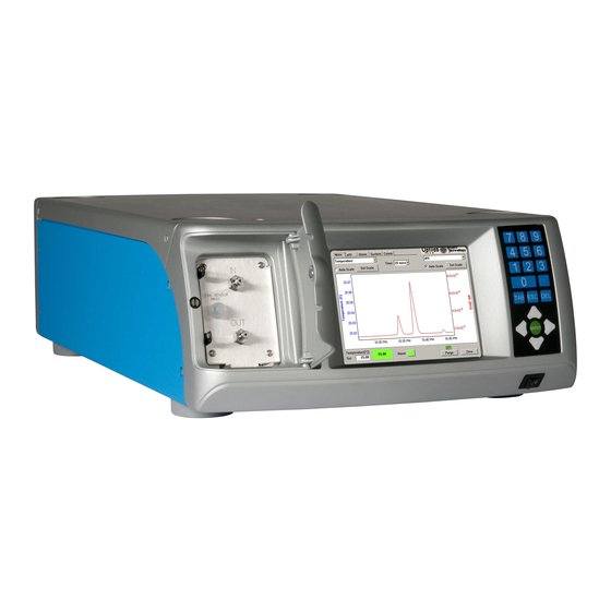
Page 13: Front Panel
LCD display and their functions. Keypad: The keypad allows you to control the LCD display. “Navigating the Optilab rEX Tabs” on page 5-2 describes how to use the keypad to navigate through the LCD display tabs. -
Page 14: Rear Panel
Nitrogen Purge Port: Provides the connection to purge the instrument with dry nitrogen in order to prevent condensation on the optical and mea- surement systems. For detailed information regarding the nitrogen purge port, see “Dry Nitrogen Connection” on page 4-8. Optilab rEX User’s Guide (M1500 Rev. F) -
Page 15: Chapter 3: Quick Start
Quick Start This chapter provides rudimentary setup procedures for first-time or expe- rienced users who want to start the Optilab rEX installation process before reading the entire manual. Detailed descriptions and important use instructions concerning the Optilab rEX are provided in the chapters that follow. -
Page 16: Setting Up The Optilab Rex
This section describes basic setup procedures for those who want to begin using the Optilab rEX as soon as possible. More details about setting up the Optilab rEX are provided in Chapter 4, “Installation and Setup”. (You may notice that the setup sequence in this chapter differs a bit from that in Chapter 4. - Page 17 Setting Up the Optilab rEX The Optilab rEX is shipped with Ethanol in the flow cell. A typical series of solvents (from polar to nonpolar) is shown below. Salt solu- tions should be considered separate steps from pure solvents. Water...
- Page 18 Chapter 3: Quick Start Optilab rEX User’s Guide (M1500 Rev. F)
- Page 19 4.1.3 Communication Connector............4-7 4.2 Fluid Connections................4-7 4.3 Dry Nitrogen Connection ..............4-8 4.4 Power On and Warm Up ..............4-9 4.5 Purging the Optilab rEX..............4-9 4.6 Instrument Stability Check .............. 4-10 Optilab rEX User’s Guide (M1500 Rev. F)
-
Page 20: Chapter 4: Installation And Setup
Chapter 4: Installation and Setup 4.1 Power and Signal Connections All power and signal connections to the Optilab rEX are made using the interfaces on the rear panel of the instrument. Refer to Figure 4-1 to view the connectors on the rear panel of the Optilab rEX. - Page 21 Appendix D, “Wire Colors”. Figure 4-3: General-purpose cable An analog out cable is supplied to connect to the Optilab rEX analog output to a DAWN or miniDAWN AUX analog input. Optilab rEX User’s Guide (M1500 Rev. F)
- Page 22 High signal, and 0 V on the signal line is interpreted as a Low signal. Input signals to the Optilab rEX must have a duration of at least 100 msec in order to be reliably detected.
- Page 23 Optilab rEX, and then send the signal to another device. The receipt of this signal by the Optilab rEX causes a mark to appear in the data on the LCD display Main tab, changes the state reported on the LCD display System tab Auto Inject input field, and causes a signal to be sent with the digital data stream indicating the time of receipt of the signal.
- Page 24 Chapter 4: Installation and Setup Analog In: Analog input Positive on red, Negative on green, and Ground on blue. The Optilab rEX digitizes an analog input in the range of ±10 V with a resolution of 0.31 mV (16 bits).
-
Page 25: Communication Connector
The tubing recommendations for the Optilab rEX are: 0.010 in. (0.254 mm) ID to the Optilab rEX inlet • 0.020 in. (0.508 mm) or larger ID from the Optilab rEX outlet to a • waste bottle or solvent recycle valve. -
Page 26: Dry Nitrogen Connection
To prevent condensation, attach a dry air or nitrogen line to the Nitrogen Purge fitting on the rear panel of the Optilab rEX (see Figure 2-2). Use a right-angle male connector and a 10-foot length of Polyethylene tubing, provided with the Optilab rEX, to connect to the Nitrogen Purge fitting. -
Page 27: Power On And Warm Up
Power On and Warm Up 4.4 Power On and Warm Up The power switch for the Optilab rEX is located on the front of the instru- ment in the lower right hand corner (see Figure 2-1). Start by powering on the instrument using this switch. -
Page 28: Instrument Stability Check
4-9. 2. Un-plumb the instrument from any fluid lines. 3. Insert a plug (shipped with the Optilab rEX) into the OUT port (see Figure 2-1) and leave the IN port open to the atmosphere. 4. From the LCD display Main tab, set the temperature set point to 25 ° C and wait approximately 30 minutes for the instrument to stabilize. - Page 29 LCD display on the front panel of the instrument. These tabs allow you to monitor, configure, and control the function and operation of the Optilab rEX. ONTENTS 5.1 Navigating the Optilab rEX Tabs............. 5-2 5.2 Main Tab ..................5-3 5.3 aRI Tab ................... 5-4 5.4 Alarms Tab..................5-5 5.5 System Tab..................
-
Page 30: Chapter 5: Using The Lcd Display
Right and Left Arrow keys: Move to another tab, or move the cursor • within a numeric field. Note: The Tab key only moves in the forward direction. The sections that follow describe the Optilab rEX LCD display tabs. Optilab rEX User’s Guide (M1500 Rev. F) -
Page 31: Main Tab
The box displays as yellow until the temperature stabilizes. When the temperature has remained within ±0.05°C of the Temperature (°C) Set value for a minimum period of 15 minutes, the box is green. Optilab rEX User’s Guide (M1500 Rev. F) -
Page 32: Ari Tab
The purge valve should be ON and both chambers should be carefully flushed with the liquid to be measured. RIU: With the purge valve ON, displays the aRI of the liquid in the flow cell. Optilab rEX User’s Guide (M1500 Rev. F) -
Page 33: Alarms Tab
Alarms Tab 5.4 Alarms Tab The Alarms tab allows you to view the current state of Optilab rEX alarms, and to set the voltage state of external alarms. If any alarm is detected, the Alarm button flashes on the Main, aRI, and Alarms tabs. - Page 34 External alarm OUT: This output signal is the logical OR of the External alarm IN, the Vapor alarm, and the Liquid leak alarm. If con- necting a device to the Optilab rEX External alarm OUT, select High or Low depending on the voltage input of the external device. If the connect- ing device expects to receive a low voltage to signal an alarm, select Low.
-
Page 35: System Tab
LED/fiber light source, view the instrument’s serial number and the Auto Inject input status, turn the LED/fiber light source on or off, and modify calibration constants and analog out parameters. Figure 5-4: System tab Optilab rEX User’s Guide (M1500 Rev. F) - Page 36 Serial number: Displays the serial number of the instrument. Software version: Displays the version number of the firmware running on the Optilab rEX. After a firmware upgrade, you must use the Restart button to restart the instrument. Constants…: Refer to “Constants Dialog” on page 5-9.
-
Page 37: Constants Dialog
This value represents the light beam position that corre- • sponds to zero dRI. Zeroing the instrument (from the front panel Main tab) updates this value. Optilab rEX User’s Guide (M1500 Rev. F) - Page 38 (the measurement time constant) is automatically set to be 2x the col- lection interval. This parameter is managed using the ASTRA V software Basic collection procedure, when the Optilab rEX is con- nected digitally to a PC via an Ethernet connection.
-
Page 39: Led Intensity Dialog
For 660 or 690 nm light sources, that optimal value is 7.8 V. Table 5-2 shows optimal voltage values for LED/fiber light sources with other wavelengths. See “Optimizing the LED/Fiber Light Source” on page 8-10 for instructions regarding this button. 5-11 Optilab rEX User’s Guide (M1500 Rev. F) - Page 40 λ < 568 568 ≤ λ < 725 725* ≤ λ * Theoretical values. Please contact Wyatt Technology Corporation for current information concerning wavelengths greater than 725 nm. The photodetector saturates slightly above 8 V, at which point an increase in light intensity no longer results in an increase in the signal voltage from the photodetector.
-
Page 41: Communications Tab
5.6 Communications Tab The Communications tab allows you to set parameters relating to com- munication with computers. The Optilab rEX is equipped for Ethernet communication. Ethernet communication allows the instrument to be pre- sented to any computer on a local area network (LAN).See Appendix E, “Instrument Connectivity”... - Page 42 Use the following IP address: Selecting this option allows you to • assign static IP Address and Subnet Mask values manually. You may need assistance from a network administrator to obtain valid static IP address and subnet mask values. 5-14 Optilab rEX User’s Guide (M1500 Rev. F)
- Page 43 6.1.1 General Information and Sample Preparation......6-2 6.1.2 HPLC Pump with Injector ............6-3 6.1.3 Syringe Pump Infusion .............. 6-3 6.1.4 Collecting Data for Optilab rEX dRI Calibration......6-4 6.2 dn/dc Measurement................ 6-6 6.3 Instrument Calibration for aRI............6-7 6.3.1 General Information..............6-7 6.3.2 Collecting Data for Optilab rEX aRI Calibration......
-
Page 44: Chapter 6: Off-Line Measurements
The lowest and highest recommended concentrations are ~0.1 mg/mL and ~29 mg/mL respectively, although 0.1mg/mL to 5mg/ mL is the most relevant range for Optilab rEX dRI calibration. Use six or more concentrations prepared within 1% or better accuracy to increase the precision of the final determination. -
Page 45: Hplc Pump With Injector
This arrangement is shown in Figure 6-1. Use 0.01 in. ID tubing between the injector and the Optilab rEX, and 0.02 in. ID tubing elsewhere. A flow rate of 0.5–1.0 mL/minute is ideal. Use a large sample loop, 0.5–1.0 mL to ensure that each injection produces a clear plateau and not a peak as it passes through the Optilab rEX. -
Page 46: Collecting Data For Optilab Rex Dri Calibration
Finally, zero the Optilab rEX by pressing Enter on the Zero button on the Main tab. After the Optilab rEX has been zeroed, it is ready to collect data and should not zeroed again until the dRI Calibration procedure is complete. - Page 47 The new dRI calibration constant must be calculated manually, using the old dRI calibration constant and the correction factor provided by ASTRA. Go to the System tab on the Optilab rEX front panel, open the Constants dialog, and enter the new dRI calibration constant. Tab to the Apply button and press Enter.
-
Page 48: Dn/Dc Measurement
The dn/dc value is the change in solution refractive index with change in solute concentration, expressed in units of mL/g. It is possible to calculate dn/dc from Optilab rEX data if the Optilab rEX dRI calibration constant and sample solution concentrations are known. -
Page 49: Instrument Calibration For Ari
Optilab rEX is flushed with a new solvent. 6.3.2 Collecting Data for Optilab rEX aRI Calibration 1. The Optilab rEX should be purged (flow liquid with the Purge on) with high-purity water for several minutes before beginning the aRI cali- bration procedure. - Page 50 Close the pane by clicking the OK button. e. Run the experiment. Introduce Solvents 1. Flow the pure solvents directly into the Optilab rEX at a constant flow rate, using a syringe pump or an HPLC pump set in the flow rate range of 0.5mL/min to 1.0mL/min.
- Page 51 ASTRA V file. You may also want to print the report. 6. Go to the System tab on the Optilab rEX, tab to the Constants button and press Enter. Enter the new values into the Optilab rEX in the Constants dialog.
-
Page 52: Absolute Refractive Index Measurement
In order to measure the absolute refractive index (aRI) of a liquid, the liquid must be present in both the sample and reference chambers of the Optilab rEX. The purge valve should be ON and both chambers should be carefully flushed with the liquid to be measured. See the previous section (aRI Calibration) for a detailed description of the recommended solvent introduction procedure for aRI measurements. -
Page 53: Chapter 7: In-Line Hplc Detection
In-Line HPLC Detection This chapter provides details about preparing samples for optimal in-line operation and measurement. ONTENTS 7.1 Conditions for In-Line Operation............. 7-2 7.2 Sample Preparation................ 7-3 7.3 Measurement.................. 7-3 Optilab rEX User’s Guide (M1500 Rev. F) -
Page 54: Conditions For In-Line Operation
Optilab rEX itself • “Main Tab” on page 5-3 outlines how to control the Optilab rEX tem- perature. The Optilab rEX is extremely stable thermally, so unless the ambient temperature fluctuates considerably, the Optilab rEX should be able to achieve a stable temperature. -
Page 55: Sample Preparation
Sample Preparation this process, to ensure that solvents are thoroughly flushed through the detector. “Purging the Optilab rEX” on page 4-9 describes solvent change procedures. The pump pressure should be noted regularly, and the system should be checked for any short-term variations in flow rate, eluent, or operating temperature. - Page 56 Chapter 7: In-Line HPLC Detection Optilab rEX User’s Guide (M1500 Rev. F)
- Page 57 Service and Maintenance This chapter provides detailed instructions on minor maintenance tasks that can be performed by the user on the Optilab rEX. ONTENTS 8.1 Replacing the LED/Fiber Light Source ........... 8-2 8.2 Cleaning After a Fluid Leak ............8-11 8.3 Cleaning the Air Intake Filter ............
-
Page 58: Chapter 8: Service And Maintenance
Replacement LED/fiber light source • Setting the Percent Max Power to Zero 1. On the Optilab rEX front panel, go to the System tab. Press Tab to move to the LED button and press Enter. Figure 8-1: LED button location... - Page 59 “0”, and press Enter. Close the LED Intensity dialog. Figure 8-2: LED Intensity dialog Note that the Optilab rEX Low Light Alarm is activated when you set the LED percent max power to 0. 3. To ensure that the LED max power setting is saved at 0%, you must restart the device by navigating to the Restart button in the System tab and allowing the Optilab rEX to shutdown and restart.
- Page 60 Removing the Old LED/Fiber Light Source CAUTION: It is strongly recommended that you wear an anti-static wristband whenever you open the Optilab rEX to help prevent potential damage to the instrumentation from electrostatic discharge. WARNING: Be sure that the power cord is disconnected from the instrument before removing the cover.
- Page 61 Replacing the LED/Fiber Light Source 2. The optical fiber mount is located on the Optilab rEX electronics board pictured below. Using a 1.5 mm hex driver, loosen both of the optical fiber mount screws. Remove one screw entirely, but do not remove the other screw.
- Page 62 This exposes the optical fiber connection port. Set blocks aside for future use. Optical fiber connection port Figure 8-8: Optical fiber connection port exposed Optilab rEX User’s Guide (M1500 Rev. F)
- Page 63 CAUTION: Unless you are replacing a damaged LED/fiber light source, you should store the removed fiber in a safe place. Take care to ensure that extra cur- vature is not introduced into the fiber during storage; this helps prolong the LED/fiber light source lifetime. Optilab rEX User’s Guide (M1500 Rev. F)
- Page 64 P1. (See [3] in the picture that follows.) 4. Move the optical fiber off of the Optilab rEX power supply, and place the optical fiber coil in the gap between the Optilab rEX thermal hous- ing and the power supply.
- Page 65 To change the front panel LED/fiber light source wavelength setting, follow these steps: 1. Navigate to the System tab on the Optilab rEX front panel. Tab to the Wavelength Change button and press Enter. Figure 8-11: Wavelength Change button location 2.
- Page 66 Chapter 8: Service and Maintenance Optimizing the LED/Fiber Light Source CAUTION: Be sure that the correct wavelength is set on the Optilab rEX front panel as described in the previous section. It is possible to destroy the LED/fiber light source if you adjust the light source Percent max power when using the incorrect wavelength setting.
-
Page 67: Cleaning After A Fluid Leak
When the liquid leak well has been emptied, the liquid leak alarm should turn off. A slight wetting of the well should not be sufficient to set off the liquid leak alarm. 8-11 Optilab rEX User’s Guide (M1500 Rev. F) -
Page 68: Cleaning The Air Intake Filter
6. If the liquid leak well contains residue from the leak, use a syringe to flush the liquid leak well with a pure solvent that is co-miscible with the solvent that has leaked (see “Purging the Optilab rEX” on page 4-9 for a list of solvent miscibilities). -
Page 69: Optilab Rex Firmware Upgrades
Optilab rEX Firmware Upgrades 8.5 Optilab rEX Firmware Upgrades For peak performance and stability of your Optilab REX, check regularly for the most recent firmware. The rEX firmware upgrades are available at the wyatt.com support center. You will be required to log in. For help logging in, visit the www.wyatt.com... - Page 70 Chapter 8: Service and Maintenance 8-14 Optilab rEX User’s Guide (M1500 Rev. F)
-
Page 71: Chapter 9: Troubleshooting
This chapter provides details about troubleshooting procedures for the Optilab rEX. ONTENTS 9.1 Low Light Alarm................9-2 9.2 Temperature Will Not Set Below 20 C ..........9-3 9.3 Noisy Baseline................9-4 9.4 Microsoft Windows Encounters Problems ........9-4 Optilab rEX User’s Guide (M1500 Rev. F) -
Page 72: Low Light Alarm
In addition to the expected low light condition that arises when changing solvents or injecting a concentration that is beyond the capabilities of the Optilab rEX, other reasons the light intensity on the photodiode array may be too low are as follows: LED Off: On the System tab, the LED dialog allows you to turn the •... -
Page 73: Temperature Will Not Set Below 20 C
(20 ° C without dry gas input, 4 ° C with dry gas input), and place a restriction capillary on the OUT port from the Optilab rEX to increase the pressure in the flow cell by 10-15 psi. The lower temperature and higher pressure increase the rate at which the bubble is dissolved. -
Page 74: Noisy Baseline
Use a syringe to inject solvent by hand into the Optilab rEX. If the noise is still not present, then the noise probably has its origins in the chromatographic system. -
Page 75: Appendix A: Acronyms And Abbreviations List
Acronyms and Abbreviations List This appendix contains a list of acronyms and abbreviations used in this manual. ONTENTS A.1 Acronyms and Abbreviations............A-2 Optilab rEX User’s Guide (M1500 Rev. F) -
Page 76: Acronyms And Abbreviations
= 0 ° C and 1 atmosphere of pressure transistor-transistor logic Volt Volts alternating current Volts direct current Optilab rEX User’s Guide (M1500 Rev. F) -
Page 77: Appendix B: Operating Principles And Theory
B.1.2 Optilab rEX Flow Cell ..............B-3 B.2 Measurement of the Beam Deflection Angle ........B-4 B.2.1 Conventional Split Photodiode Based Instrument ....B-4 B.2.2 Wyatt Technology Corporation Beam Positioning Technology .. B-4 Optilab rEX User’s Guide (M1500 Rev. F) -
Page 78: Basic Principles
Appendix B: Operating Principles and Theory B.1 Basic Principles B.1.1 Conventional Flow Cell The Optilab rEX is a special variation of the deflection-type differential refractometer. For this type of differential refractometer, a light beam passes through a flow cell containing reference and sample fluids, and undergoes an angular deflection based upon the refractive index difference between the two fluids. -
Page 79: Optilab Rex Flow Cell
(aRI) of a fluid, as well as the differential refractive index (dRI) between two fluids. The flow cell in the Optilab rEX is shown in Figure B-2. The reference chamber has a non-90 angle on its exit face. -
Page 80: Measurement Of The Beam Deflection Angle
The Optilab rEX records voltages from each of the 512 elements of the photodiode array 10–20 times per second. To obtain the most precise possible measurement, the signal from each element is measured many times and the results averaged together. - Page 81 The computational power to perform these mathematically intensive oper- ations at such rates was unavailable 15 years ago, but now fits into the small Pentium-class processor inside your Optilab rEX. Using a photo- diode array and advanced mathematical analysis techniques, the light beam position may be measured to within about 25 Angstroms.
- Page 82 Appendix B: Operating Principles and Theory Optilab rEX User’s Guide (M1500 Rev. F)
-
Page 83: Appendix C: Optilab Rex Specifications
Optilab rEX Specifications This appendix provides specification details for the Optilab rEX instrument. ONTENTS C.1 Specifications ................. C-2 Optilab rEX User’s Guide (M1500 Rev. F) -
Page 84: Specifications
168 mm x 357 mm x 595 mm (H x W x D) Weight: 11.5 kg Note: Short term peak-to-peak noise is measured as per ASTM-E1303-95(2000) using a 4-second time constant and temperature controlling at 25 ° C. Optilab rEX User’s Guide (M1500 Rev. F) -
Page 85: Appendix D: Wire Colors
Wire Colors This appendix provides details about earlier revisions of the general- purpose cable supplied by Wyatt Technology Corporation. ONTENTS D.1 Earlier Cable Revisions ..............D-2 Optilab rEX User’s Guide (M1500 Rev. F) -
Page 86: Earlier Cable Revisions
Signal Ground Auto Inject In Signal Signal Ground Analog In Positive Negative Ground Analog Out Positive Negative Ground Recycle Out Signal Signal Ground Alarm Out Signal Signal Ground Auto Inject Out Contact Contact Optilab rEX User’s Guide (M1500 Rev. F) -
Page 87: Appendix E: Instrument Connectivity
E.4 Connecting via USB ............... E-12 E.5 Connecting via Ethernet When Not on a LAN ........ E-15 E.6 Instrument Network Settings ............E-17 E.7 Accessing Instruments with ASTRA V..........E-18 E.8 Troubleshooting and Diagnostics ........... E-19 Optilab rEX User’s Guide (M1500 Rev. F) -
Page 88: Introduction
Appendix E: Instrument Connectivity E.1 Introduction These instructions contain a pictorial overview for connecting your Optilab rEX to a computer for data collection. The instructions are divided into the following topics: Components to be used for instrument connectivity (page E-3). All •... -
Page 89: Components Used
Ethernet port, which is to be used for all connections in these instructions. The built-in USB port exhibits technical problems on some computers, and Wyatt Technology recommends using the Ethernet port instead. Please see “Connecting via USB” on page E-12 for instructions on establishing a USB connection. -
Page 90: Lan Connection
USB port. Figure E-3 shows the Ethernet (yellow arrow) and USB (green arrow) ports on a standard laptop computer. USB port Ethernet port Figure E-3: Ethernet and USB ports on the computer Optilab rEX User’s Guide (M1500 Rev. F) -
Page 91: Crossover Cable
A crossover cable can be used to make a direct connection from the instru- ment to an Ethernet port on a computer or to an Ethernet to USB adapter. Note that the crossover cable shipped with Wyatt Technology instruments is yellow to distinguish it from a standard Ethernet cable. Be careful to only use the yellow crossover cable where indicated. -
Page 92: Ethernet To Usb Adapter
LAN via the computer's Ethernet port, and the instruments connected to the computer via USB. The Ethernet to USB adapter supplied by Wyatt Technology will look similar to the one in Figure E-6. Figure E-6: Standard Ethernet to USB adapter The Ethernet cable is plugged into the port with the yellow arrow, and the USB plug (green arrow) is plugged into a USB port on the computer. -
Page 93: Ethernet Switch
Ethernet switches are used to connect several Ethernet cables to one resource, such as the LAN socket in Figure E-2. The Ethernet switch supplied by Wyatt Technology will look similar to the five port switch shown below. Note that Ethernet cables can be connected to the switch in any order or position. -
Page 94: Connecting To A Lan
Plug the instrument into a LAN wall socket using a standard Ethernet cable (Figure E-5). The computer that is to communicate with the instru- ment must be on the same LAN. Figure E-8: Connection for one instrument to LAN Optilab rEX User’s Guide (M1500 Rev. F) -
Page 95: One Instrument And Computer To Lan
LAN. In this configuration, the computer can access the LAN and the instrument, and the instrument can be accessed from any other computer on the LAN. Figure E-9: Instrument and computer connected to LAN via Ethernet switch Optilab rEX User’s Guide (M1500 Rev. F) -
Page 96: Multiple Instruments To Lan
LAN via an Ethernet switch (Figure E-7). The instruments can be accessed via any computer on the LAN. Figure E-10: Two instruments connected to LAN via an Ethernet switch E-10 Optilab rEX User’s Guide (M1500 Rev. F) -
Page 97: Multiple Instruments And Computer To Lan
LAN and the instruments, and the instruments can be accessed from any other computer on the LAN. Figure E-11: Two instruments and computer to LAN via an Ethernet switch E-11 Optilab rEX User’s Guide (M1500 Rev. F) -
Page 98: Connecting Via Usb
You may be prompted to install drivers for the Ethernet to USB adapter the first time it is plugged into the computer. To install the drivers, insert the CD that came with the adapter and follow the Windows instructions. E-12 Optilab rEX User’s Guide (M1500 Rev. F) -
Page 99: One Instrument To Usb Using An Ethernet Switch
You may be prompted to install drivers for the Ethernet to USB adapter the first time it is plugged into the computer. To install the drivers, insert the CD that came with the adapter and follow the Windows instructions. E-13 Optilab rEX User’s Guide (M1500 Rev. F) -
Page 100: Multiple Instruments To Usb
You may be prompted to install drivers for the Ethernet to USB adapter the first time it is plugged into the computer. To install the drivers, insert the CD that came with the adapter and follow the Windows instructions. E-14 Optilab rEX User’s Guide (M1500 Rev. F) -
Page 101: Connecting Via Ethernet When Not On A Lan
E.5.1 One Instrument to Computer Using Crossover Cable Connect the yellow crossover cable from the instrument directly to the Ethernet port on the computer. Figure E-15: Connecting one instrument to computer via yellow crossover cable E-15 Optilab rEX User’s Guide (M1500 Rev. F) -
Page 102: One Instrument To Computer Using An Ethernet Switch
Connect each instrument to the Ethernet switch using a standard Ethernet cable. Then connect the switch to the computer Ethernet port using a standard Ethernet cable. Figure E-17: Connecting multiple instruments to computer via Ethernet switch E-16 Optilab rEX User’s Guide (M1500 Rev. F) -
Page 103: Instrument Network Settings
0.0.0.0. At this point, it should be possible to connect to the instrument from the computer. If you want to use a static IP address and subnet mask, please contact your IT department to obtain a valid address and mask. E-17 Optilab rEX User’s Guide (M1500 Rev. F) -
Page 104: Accessing Instruments With Astra V
The Diagnostic Manager application should launch, which can be used to verify the instrument connection. If it is not possible to connect to an instrument after following these instructions, read “Troubleshooting and Diagnostics” on page E-19. E-18 Optilab rEX User’s Guide (M1500 Rev. F) -
Page 105: Troubleshooting And Diagnostics
Please log in to the Support Center on the Wyatt Technology web site (www.wyatt.com ) and download the configuration instructions under Software → Computer Info, or contact customer service at Wyatt Technology to obtain the instructions. - Page 106 Appendix E: Instrument Connectivity If the instrument is not connected properly, the result will be similar to that shown in Figure E-20. Figure E-20: Failure to connect to instrument using ping E-20 Optilab rEX User’s Guide (M1500 Rev. F)
-
Page 107: Appendix F: Warnings
Warnings This appendix provides a list of warnings that should be read and under- stood when using the Optilab rEX. ONTENTS F.1 List of Warnings ................F-2 Optilab rEX User’s Guide (M1500 Rev. F) -
Page 108: List Of Warnings
LED coupled to an optical fiber. The LED in this LED/fiber unit is mounted to the top electronics board in the Optilab rEX near connector P3. The fiber brings the light from the LED into the optical system. - Page 109 5-10 calibration constant 5-9 baseline noise 9-4 offset 5-9 beam deflection angle, measuring B-4 range and sensitivity C-2 bubble in flow cell 9-2 setting zero value of 4-5 , 4-10 , 5-4 Index-1 Optilab rEX User’s Guide (M1500 Rev. F)
- Page 110 ENTER key 5-2 in-line 7-2 error condition 9-4 off-line 6-2 ESC key 5-2 HPLC fittings for fluid connections 3-2 , 4-7 Ethanol, shipped with Optilab rEX 3-3 , 4-9 HPLC pump with injector 6-3 Ethernet cable E-5 communication 5-13 ID tubing 6-3...
- Page 111 Purge Off button, Main tab 5-4 Nitrogen pressure alarm, Alarms tab 5-6 purge port, nitrogen 2-4 Nitrogen pressure field, Alarms tab 5-6 purging (flushing) Optilab rEX 3-2 , 4-9 nitrogen purge port 2-4 noise rear panel 2-4 , 4-2 acceptable levels of 4-10 Index-3 Optilab rEX User’s Guide (M1500 Rev.
- Page 112 6-3 service pack E-19 System Constants field, Constants dialog wire colors 4-3 prior versions D-2 system crash 9-4 Wyatt Technology, contact information for System tab 4-5 , 5-7 wyatt.com 8-13 Index-4 Optilab rEX User’s Guide (M1500 Rev. F)
- Page 113 Index x-axis field, Main tab 5-3 Zero button, Main tab 4-10 , 5-4 Zero In signal 4-5 Zero selection 3-3 y-axis field, Main tab 5-3 on auto inject signal 5-8 Index-5 Optilab rEX User’s Guide (M1500 Rev. F)
-
Page 114: Index
Index Index-6 Optilab rEX User’s Guide (M1500 Rev. F)
Need help?
Do you have a question about the Optilab rEX and is the answer not in the manual?
Questions and answers