Table of Contents
Advertisement
Quick Links
GOS-6051/6050/6031/6030 OSCILLOSCOPE
USER MANUAL
CONTENTS
1.
PRODUCT INTRODUCTION.................................................
1-1.Description.......................................................
1-2.Feature.............................................................
2.
TECHNICAL SPECIFICATIONS.............................. 4
3.
PRECAUTIONS BEFORE OPERATION......................
3-1.Unpacking the Oscilloscope...................................
3-2.Checking the Line Voltage.....................................
3-3.Environment.....................................................
3-4.Equipment Installation and Operation......................
3-5.CRT Intensity...................................................
3-6.Withstanding Voltage of Input Terminals..................
4.
PANEL INTRODUCTION.........................................
4-1.Front Panel.......................................................
4-2.Rear Panel........................................................
5.
OPERATION METHOD...........................................
5-1.Readout Display..................................................
5-2.Connecting Input Signals......................................
5-3.Adjustment and Checks.......................................
5-4.Function Check..................................................
5-5.Basic Operation...................................................
5-6.Measurement Application.....................................
6.
MAINTENANCE...................................................
6-1.Fuse Replacement...............................................
6-2.Line Voltage Conversion.......................................
6-3.Cleaning..........................................................
7.
BLOCK DIAGRAM................................................ 48
⎯
⎯
i
PAGE
1
1
2
7
7
7
8
8
8
8
8
11
26
28
28
30
31
33
35
44
46
46
46
47
GOS-6051/6050/6031/6030 OSCILLOSCOPE
USER MANUAL
SAFETY TERMS AND SYMBOLS
These terms may appear in this manual or on the product:
WARNING. Warning statements identify condition or
practices that could result in injury or loss of life.
CAUTION. Caution statements identify conditions or
practices that could result in damage to this product or
other property.
The following symbols may appear in this manual or on the product:
DANGER
ATTENTION
Protective
High Voltage refer to Manual Conductor
Terminal
⎯
⎯
ii
Earth(ground)
Terminal
Advertisement
Table of Contents

Related Manuals for Good Will Instrument GOS-6051


Summary of Contents for Good Will Instrument GOS-6051
-
Page 1: Table Of Contents
GOS-6051/6050/6031/6030 OSCILLOSCOPE GOS-6051/6050/6031/6030 OSCILLOSCOPE USER MANUAL USER MANUAL CONTENTS PAGE SAFETY TERMS AND SYMBOLS PRODUCT INTRODUCTION..........1-1.Description………………………………………………. These terms may appear in this manual or on the product: 1-2.Feature…………………………………………………..TECHNICAL SPECIFICATIONS………………………… 4 WARNING. Warning statements identify condition or PRECAUTIONS BEFORE OPERATION…….…………... - Page 2 GOS-6051/6050/6031/6030 OSCILLOSCOPE GOS-6051/6050/6031/6030 OSCILLOSCOPE USER MANUAL USER MANUAL equipment and/or user instructions for details. As a guide, cable of FOR UNITED KINGDOM ONLY 0.75mm should be protected by a 3A or 5A fuse. Larger conductors would normally require 13A types, depending on the connection method used.
-
Page 3: Product Introduction
No.7-1, Jhongsing Road, Tucheng City, Taipei County 236, Taiwan GOOD WILL INSTRUMENT (SUZHOU) CO., LTD. No.69 Lushan Road, Suzhou New District Jiangsu, China. The GOS-6051/50/31/30 series are 50MHz/30MHz, two-channel, portable declares that the below mentioned product oscilloscopes for general purpose use. A microprocessor-based operating system... -
Page 4: 1-2.Feature
For applying a blanking signal from an external source. The trace displayed between the trace and the graticule line. on the screen may be intensity-modulated where pulse signal or time-scale 2) Frequency Counter (GOS-6051/6031) marks are required. A built-in 6 digits frequency counter is accurate within the range of ±... -
Page 5: Technical Specifications
Trigger Slope “+” or “- ” polarity. Max. input voltage: 30V (DC +AC peak) at 1kHz GOS-6051/ CH1, VERT- or less. GOS-6050 MODE Input Impedance: approx. 33kΩ(GOS-6051/6050) 20Hz~5MHz 0.5 DIV 2.0 DIV 200mV 47kΩ(GOS-6031/6030) 5MHz~40MHz 1.5 DIV 3.0 DIV 800mV Sensitivity Accuracy 1mV~2mV/DIV ±... -
Page 6: Precautions Before Operation
Horizontal: ±4 DIV Display Digits: Max. 6-digits decimal. The product has been fully inspected and tested before shipping from the READOUT Frequency Range: 50Hz~50MHz (GOS-6051) factory. Upon receiving the instrument, please unpack and inspect it to check 50Hz~30MHz (GOS-6031) Accuracy: ±0.05%: 50Hz~1kHz. -
Page 7: 3-3.Environment
GOS-6051/6050/6031/6030 OSCILLOSCOPE GOS-6051/6050/6031/6030 OSCILLOSCOPE USER MANUAL USER MANUAL 4. PANEL INTRODUCTION 3-3.Environment After the instrument is switched on, all the important settings are displayed in The normal ambient temperature range of this instrument is from 0° to 40°C the readout. The LED’s located on the front panel assist operation and indicate (32°... -
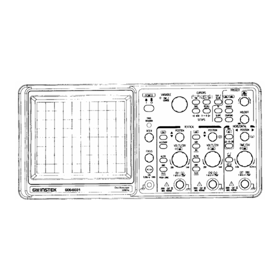
Page 8: 4-1.Front Panel
GOS-6051/6050/6031/6030 OSCILLOSCOPE GOS-6051/6050/6031/6030 OSCILLOSCOPE USER MANUAL USER MANUAL 4-1.Front Panel Display controls The display controls adjust the on-screen appearance of the waveform and provide a probe compensation signal source. Front panel of GOS-6031/6051 (1) POWER – Pushbutton When switch on the oscilloscope to have all LEDs lighted and wait a few seconds, the normal operation mode is present. - Page 9 Pressing the knob to switch the TEXT/ILLUM on or off. In the cursor mode, pressing the VARIABLE control knob to select the cursor (8) CURSORS MEASUREMENT FUNCTION (GOS-6051/6031) position between FINE and COARSE adjustment. When select FINE There are two pushbutton and associated the VARIABLE(9) control knob.
- Page 10 USER MANUAL USER MANUAL Vertical controls (10). ◄ MEMO- 9 ► —SAVE/RECALL(GOS-6051/6031) The instrument contains 10 non-volatile memories, which can be used by the The vertical controls select the displayed signals and control the amplitude operator to save instrument setting and to recall them. It relates to all controls characteristics.
- Page 11 GOS-6051/6050/6031/6030 OSCILLOSCOPE GOS-6051/6050/6031/6030 OSCILLOSCOPE USER MANUAL USER MANUAL (15) ALT/CHOP The deflection coefficients and additional information regarding the active The pushbutton has two functions, which are required and available only channels are displayed in the readout. when both channels are active.
-
Page 12: Horizontal Controls
GOS-6051/6050/6031/6030 OSCILLOSCOPE GOS-6051/6050/6031/6030 OSCILLOSCOPE USER MANUAL USER MANUAL (25)H POSITION (23)CH1-X—Input BNC socket The control knob enables a horizontal position shift of the signals. In This BNC socket is the signal input for channel 1. In X-Y mode, signals at combination with MAG the function makes it possible to shift any part of this input are used for the X deflection. -
Page 13: Trigger Controls
GOS-6051/6050/6031/6030 OSCILLOSCOPE GOS-6051/6050/6031/6030 OSCILLOSCOPE USER MANUAL USER MANUAL Trigger controls (28)×1/MAG The trigger controls determine the sweep start timing for both signal. Pressing the pushbutton the select the sweep time between ×1 (normal) and MAG (magnify). If the MAG function, the signal display will be expanded and consequently only a part of the signal curve is visible. - Page 14 GOS-6051/6050/6031/6030 OSCILLOSCOPE GOS-6051/6050/6031/6030 OSCILLOSCOPE USER MANUAL USER MANUAL will be displayed. (32)TV—Pushbutton for video sync signal selection Use this mode when effecting synchronization to a very low frequency Separate the video sync signal from the composite waveform and direct it signal (25Hz or less).
- Page 15 GOS-6051/6050/6031/6030 OSCILLOSCOPE GOS-6051/6050/6031/6030 OSCILLOSCOPE USER MANUAL USER MANUAL to move the trigger point toward the negative peak of the trigger signal. (34)COUPLING— When the setting (voltage) value is out of the changing portion of the Pressing the pushbutton to select the trigger coupling. The actual setting is observation waveform, the synchronization sweep stops.
-
Page 16: 4-2.Rear Panel
GOS-6051/6050/6031/6030 OSCILLOSCOPE GOS-6051/6050/6031/6030 OSCILLOSCOPE USER MANUAL USER MANUAL 4-2.Rear Panel (41)Z-Axis Input—BNC socket The rear panel provides input power and additional signal connections. Connect external signals to the Z-axis amplifier for intensity modulating the CRT display. This terminal is DC-coupled. The intensity is lowered by a positive signal, while it is increased by a negative signal. -
Page 17: Operation Method
GOS-6051/6050/6031/6030 OSCILLOSCOPE GOS-6051/6050/6031/6030 OSCILLOSCOPE USER MANUAL USER MANUAL 5. OPERATION METHOD This section contains basic operation information and techniques that should be considered before proceeding any measurement. As for the location and function of instrument controls, connectors, and indicators, refer to the “Instruction of Front Panel and Rear Panel”... -
Page 18: 5-2.Connecting Input Signals
GOS-6051/6050/6031/6030 OSCILLOSCOPE GOS-6051/6050/6031/6030 OSCILLOSCOPE USER MANUAL USER MANUAL 5-2.Connecting Input Signals 5-3.Adjustments and checks Grounding Trace Rotation Adjustment The most reliable signal measurements are made when the oscilloscope and Normally, when the trace is in parallel with the center horizontal graticule line, the unit under test are connected by a common reference (ground lead) in there will be no need to adjust the TRACE ROTATION. -
Page 19: 5-4.Function Check
GOS-6051/6050/6031/6030 OSCILLOSCOPE GOS-6051/6050/6031/6030 OSCILLOSCOPE USER MANUAL USER MANUAL 5-4.Function Check shown in figure 5-2. If either probe needs to be adjusted, proceed the step 8. If either probe does not need to be adjusted, proceed the “Function Check”. When you start to check the operation of your oscilloscope, proceed the following instruction: 1. -
Page 20: 5-5.Basic Operation
GOS-6051/6050/6031/6030 OSCILLOSCOPE GOS-6051/6050/6031/6030 OSCILLOSCOPE USER MANUAL USER MANUAL 5-5.Basic Operation 4. Set both CH1 and CH2 COUPLING to GND. Displaying CH1 or CH2 5. Use the CH1 and CH2 POSITION controls to align both traces on the center To display the signal from a signal channel, pressing briefly the CH1 or CH2 graticule. - Page 21 GOS-6051/6050/6031/6030 OSCILLOSCOPE GOS-6051/6050/6031/6030 OSCILLOSCOPE USER MANUAL USER MANUAL Displaying the sum or difference of CH1 and CH2 Comparing Frequency and phase (X-Y Operation) To display the algebraic sum or difference of CH1 and CH2, proceed the To compare the frequency and phase between two signals by using the X-Y following steps: mode.
- Page 22 GOS-6051/6050/6031/6030 OSCILLOSCOPE GOS-6051/6050/6031/6030 OSCILLOSCOPE USER MANUAL USER MANUAL Magnifying Waveform Events Use the MAG pushbutton to view small portions of a waveform as which is MAG-ALT Function too far back from the starting point to view by using the TIME/DIV control.
- Page 23 GOS-6051/6050/6031/6030 OSCILLOSCOPE GOS-6051/6050/6031/6030 OSCILLOSCOPE USER MANUAL USER MANUAL Operating Hold off time Control Observing the Synchronization of two Waveforms When the measured signal is a complex waveform with two or more repetition When two signals of the CH1 and CH2 have the same frequencies with an...
- Page 24 GOS-6051/6050/6031/6030 OSCILLOSCOPE GOS-6051/6050/6031/6030 OSCILLOSCOPE USER MANUAL USER MANUAL The VERT-MODE triggering is not possible when the signal is applied only to Triggering of Video signal one channel as shown in Figure 5-12 below: In the work concerned with TV, complex signals and containing video signal, blanking pedestal signal, and synchronizing signal are often measured.
-
Page 25: 5-6.Measurement Application
GOS-6051/6050/6031/6030 OSCILLOSCOPE GOS-6051/6050/6031/6030 OSCILLOSCOPE USER MANUAL USER MANUAL 5-6.Measurement Application (GOS-6051/6031) Figure 5-16: Cursor Measurement (a).Typical △V (Voltage difference) for AC The oscilloscope has a cursor measurement system for making accurate, voltage. direct-readout voltage, time and frequency measurements. The measurements When both CH1 and CH2 are turned on, the measurement value of CH1(△V1). -
Page 26: Maintenance
GOS-6051/6050/6031/6030 OSCILLOSCOPE GOS-6051/6050/6031/6030 OSCILLOSCOPE USER MANUAL USER MANUAL 6-3.Cleaning 6.MAINTENENCE To clean the oscilloscope, use a soft cloth dampened in a solution of mild The following instructions are executed by qualified personnel only. To avoid detergent and water. Do not spray cleaner directly onto the oscilloscope electrical shock, do not perform any servicing other than the operating instructions because it may leak into the cabinet and cause damage. -
Page 27: Block Diagram
GOS-6051/6050/6031/6030 OSCILLOSCOPE USER MANUAL 7.Block Diagram ⎯ 48 ⎯...
Need help?
Do you have a question about the GOS-6051 and is the answer not in the manual?
Questions and answers