Table of Contents
Advertisement
Quick Links
User's Manual
CO2 Sampling Data Logger
Models Covered
ESCM‐01 ESCM‐02
ESCM‐03
ESCM‐50 ESCM‐56
See Table 1 on page 7 for details.
WARNING!
Install our complimentary GasLab
software before connecting your CO2 Meter product(s) to
®
your computer. Failure to do so may affect the ability for GasLab
to detect your meter.
®
Save meter information for future reference
Model Number:
Serial Number:
Purchase Date:
Copyright © 2015 CO2 Meter, Inc. All Rights Reserved.
Rev. 2.0
Advertisement
Table of Contents

Subscribe to Our Youtube Channel
Summary of Contents for Co2meter ESCM-01
- Page 1 User’s Manual CO2 Sampling Data Logger Models Covered ESCM‐01 ESCM‐02 ESCM‐03 ESCM‐50 ESCM‐56 See Table 1 on page 7 for details. WARNING! Install our complimentary GasLab software before connecting your CO2 Meter product(s) to ® your computer. Failure to do so may affect the ability for GasLab to detect your meter. ® Save meter information for future reference Model Number: Serial Number: Purchase Date: Copyright © 2015 CO2 Meter, Inc. All Rights Reserved. Rev. 2.0...
- Page 2 Sampling Data Logger User’s Manual WARNING! Install our complimentary GasLab software before connecting your ® CO2 Meter product(s) to your computer. Failure to do so may affect the ability for GasLab to detect your meter. If this happens, please follow the ® instructions in the “USB Driver Installation Instructions” section on page 15 of this manual. PAGE 2 of 17...
-
Page 3: Table Of Contents
Sampling Data Logger User’s Manual Table of Contents WELCOME ........................4 IMPORTANT SAFEGUARDS ................... 4 PACKAGE CONTENTS ....................5 ....................... 5 PTIONAL CCESSORIES GASLAB SOFTWARE ....................5 ® .................... 5 INIMUM YSTEM EQUIREMENTS ......................... 7 OWERING THE ETER PRODUCT OVERVIEW ..................... 7 ......................8 NSTRUMENT VERVIEW ........................8 ... -
Page 4: Welcome
Sampling Data Logger User’s Manual Welcome Thank you for purchasing our meter. Please take some time to read through this manual in order to become familiar with the meter. Also, please pay special attention to the important safeguards. Important Safeguards To reduce the risk of fire, electrical shock and/or injury to persons, basic safety precautions should always be followed when using electrical appliances, including the following: READ ALL INSTRUCTIONS BEFORE USING THIS METER. INSTALL GasLab SOFTWARE BEFORE CONNECTING METER TO A COMPUTER. ® Use only the included power supply to operate this meter. Inappropriate voltage supply could cause irreparable damage to this device. Do NOT use rechargeable AA batteries. Duracell brand AA Alkaline batteries are recommended Do not store the meter with the AA Alkaline batteries installed to prevent the potential for battery leakage. Make sure that the tubes are securely attached to the meter before sampling a closed environment. Do not operate with an obstructed sample path. This meter is not designed for outdoor use. Do not expose this meter to water or any liquids. Do not operate this meter if the enclosure is opened. Do not operate the device if it is malfunctioning. SAVE THESE INSTRUCTIONS! PAGE 4 of 17... -
Page 5: Package Contents
(2) 1/8” Barb tubing bulkhead (2) 1/8” Barb 10‐32 UNF fittings (2) Particulate filter (CM‐0117) (2) Hydrophobic filter (CM‐0118) (1) Moisture trap (CM‐0112) Optional Accessories If the meter is to operate in environments where humidity is very high (>95% RH), an Extreme Moisture Filter (CM‐ 0103) can be purchased separately. This filter will allow free flow of sampled air while keeping moisture out of the meter. A 10,000 Hr. pump is also available at the time of purchase. Note: Please contact our technical support staff for more details about these accessories. GasLab Software ® IMPORTANT: M AKE SURE TO INSTALL SOFTWARE BEFORE CONNECTING YOUR METER TO YOUR COMPUTER Minimum System Requirements To utilize our complimentary software, the computer must meet the following minimum requirements: 1GHz processor with 1GB RAM, 1GB free disk space (2GB free disk space for 64‐bit systems). Windows XP*/7/8/8.1 with Microsoft .NET Framework 4.0** or later. On Intel‐based Mac computers, GasLab software can run using a Windows 7/8 virtual machine software ® such as VMware Fusion® or similar. *Microsoft .NET is not supported on Media Center or Tablet editions. **Installer will optionally install .NET Framework. Visit www.co2meter.com/pages/downloads to download our complimentary GasLab software to your ® computer. You can also download the GasLab user manual in PDF from this page. ® PAGE 5 of 17... - Page 6 Sampling Data Logger User’s Manual Please read the GasLab user manual carefully to become more familiar with how the software works so that you ® can get the maximum benefit from this useful tool. Install the GasLab software first to ensure that the proper driver, necessary for the meter, is installed on your ® computer before connecting the meter. Figure 2: GasLab download page (Internet Explorer 11 shown) ® Follow the steps and instructions prompted by your computer’s operating system. Make sure you have administrator privileges in order to install this program. NOTE: We strongly recommend allowing GasLab to install drivers for the meter automatically. ® Software Capabilities Our GasLab software will allow users to: ® Manage and download logs Configure Sensor Adjust logging intervals Calibrate the meter Automatic data logging when meter is powered ON Data logging session status displayed on LCD screen Collect data real‐time PAGE 6 of 17...
-
Page 7: Powering The Meter
Sampling Data Logger User’s Manual Powering the Meter This meter can be powered by four (4) AA size batteries (not included) but sampling units can also be powered by the included 6VDC international wall power supply. These units should NOT be powered using the included USB cable since it supplies inconsistent voltage to the meter, which degrades sensor accuracy. If the unit is not going to be used for an extended period of time, batteries should be removed to prevent damage due to potential battery leakage. The power switch on the left side of the meter turns the unit ON/OFF. The LOG switch on the right side of the meter enables/disables data logging and pump function. Product Overview This portable battery‐powered CO2Meter, Inc. meter is designed to measure carbon dioxide (CO2) in real time in inaccessible areas for applications such as, but not limited to fermentation vats & barrels, biological incubators, and CO2 leak detection. Meters with logging capabilities are designed to record CO2 concentration level data over periods of time. It stores up to 15,000 collected data points to its internal memory to be retrieved at a later time for analysis. When combined with our GasLab software, you can also see real‐time data on your computer’s screen. These meters are ® ideal for applications such as, but not limited to CO2 monitoring of products with modified atmosphere packaging (MAP), monitoring of mold production in areas used to store grains, and testing of fire suppression systems. Its built‐in 1,000 hours sampling micro‐pump (10,000 Hr. optional) ensures reliable operation for persistent readings based on user‐selected time intervals. Scientific devices such as this sampling meter require users to have intimate knowledge of the meter’s features, limitations, operation, required software, and specifications prior to use. CO2Meter, Inc. highly recommends reading this user’s manual before operating this meter, especially the Important Safeguards section on page 4. The table below shows all available models and their respective characteristics. Table 1: Meter models covered in this manual Model # (P/N) CO2 Level Meter Type CM‐0001 Sampling Logger CM‐0002 Sampling Logger CM‐0003 100% Sampling Logger CM‐0050 Sampling Logger CM‐0056... -
Page 8: Instrument Overview
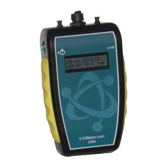
Sampling Data Logger User’s Manual USB Connector (covered) Connect included USB cable to communicate with unit. Instrument Overview Barb Fitting (x2) USB Connector (cover removed) LOG Switch Power Switch Turns logging & Turns the meter Inlet Outlet pump ON/OFF. ON/OFF. Rubber Boot (x2) Protects meter and improves grip. Display Shows CO2 concentration level, data Power Jack logging and free Connect included memory space. power supply. Detector Principal The CO2 sensor inside this meter uses NDIR (non‐dispersive infrared) technology to sense, as a function of transmitted light, the concentration of CO2 in the air. This meter has been factory calibrated to operate within the specified range and precision. PAGE 8 of 17... -
Page 9: Operation Guide
Sampling Data Logger User’s Manual Operation Guide Make sure you read through these instructions thoroughly before using the meter. This guide will help you become more familiar with the meter in order to be as productive as possible in a short period of time. Please read the Important Safeguards on page 4 before continuing. IMPORTANT: Follow these instructions to ensure proper set up: 1. Download the GasLab software to your computer as shown in the GasLab Software section on page 5. ® ® 2. Power the meter using the included universal power supply. Turn ON the meter. 3. Wait until the display changes colors to visually confirm it has reset successfully after connecting it to a computer. Connecting Meters The first time the meter is connected to your computer, the operating system will install the necessary USB drivers as shown in Figure 3. This process could take a few minutes. Figure 3: USB Driver Installation. LCD Display The Liquid Crystal Display (LCD) shows the following features: CO2 concentration level in parts‐per‐million (ppm) for 1% and 5% models CO2 concentration level in percentage format (##.##%) for all other models Logging ON/OFF Percentage of free memory Data Storage This meter features an internal memory capable of storing 15,000 data points. Due to the nature of their design, these meters will need to be initialized before operation and its logging period and real‐time clock will need to be set under the “Settings” menu. Logging Data Once the GasLab software has been installed and the meter is connected to the computer, you can gather data in a ® variety of ways. Data can be collected in real time, data logs can be downloaded from the meter’s memory and saved to the computer, and data can be reviewed on the meter’s LCD display. -
Page 10: Setup
Sampling Data Logger User’s Manual 1. Turn the meter ON. 2. The meter must be started at least 1 minute prior to deployment and data logging to allow the CO2 sensor time to warm‐up and calibrate. 3. Set the logging interval as desired and commence logging by depressing the “Log” button on the right side of the meter. 4. When data logging is completed, turn the “Log” OFF. NOTE: Refer to the GasLab User’s Manual for more information. ® Setup CO2Meter, Inc.’s sampling meters will require minimal setup since they are designed to be portable. The most important aspect of the setup involves connecting the sampling hoses and ensuring proper setup. The Instrument Overview section on page 8 shows the labeled components of these meters, as referenced throughout the rest of this manual. Data Logger Models These models feature an internal memory capable of storing data when not connected to a computer. These units will allow you to simultaneously read and store CO2 concentration level data. Due to the nature of their design, these units should be connected to your computer first, before operation, in order to initialize and set the logging interval and real‐time clock. Insert four (4) AA size batteries into this unit or connect the unit to the included power supply. In order to initialize data logging functionality, the unit MUST be connected to the computer with data logging switched to OFF, and the GasLab software started. Once the unit has been connected, click on the “Configure Sensor” button in the GasLab ® ® interface, set the data logging interval and pump periods as desired. We recommend leaving the pump interval to the default 10‐second period. For the pump period, we recommend 10 or more seconds. The pump PWM period can also be adjusted for advanced applications, with 1 being full duty cycle, and values approaching 255 being the shortest duty cycle. The pump mode should always be set to “Data logging” for proper operation of the unit. All models have an internal coin cell CR‐2032 3V battery backup for the real‐time clock. This battery is inserted in the factory for your convenience and should last the lifetime of the product. Settings Settings – allows you to access all the parameters, options, outputs, communications, and date/time settings to be changed or programmed. -
Page 11: Port Settings
Sampling Data Logger User’s Manual Port Settings Here you can configure and activate ports that control additional accessories such as the device Modbus address. Please call technical support for guidance and important information before making changes to the configuration of any of these ports. You can reach us during regular business hours at (386) 256‐4910 or send us a message to support@co2meter.com. Time/Date Settings Here you can change the date and time on the meter for more accurate reference on the records. The default time of your meter could vary depending on your location. Review these settings before you start using the meter. Logging Settings Here you can change the logging interval and duration. This will enable you to collect the data for a period of time in a specific logging interval. This screen also gives you the option to set the desired pump interval. Remember to synchronize the pump before, during, or after the logging interval to read and collect the correct reading according to the application. Closed Loop Operation Figure 4: Closed Loop Open Loop with Environmental Exhaust Figure 5: Open Loop In order to use this meter properly, hoses/tubing must be attached to the inlet and outlet barb fittings securely. The pump will draw air from the inlet by vacuum effect, push it to the sensing chamber through the sensor, and then exhaust the air outside the meter through the outlet. PAGE 11 of 17... -
Page 12: Quick Start Guide
Sampling Data Logger User’s Manual We recommend installing the included humidity/contaminate filter to ensure the sensing chamber and pump baffle stays clear and corrosion‐free. Replacements filters are available on CO2meter.com. Particulate Filter Figure 6: Filter Installation and Orientation Quick Start Guide IMPORTANT: M AKE SURE TO INSTALL SOFTWARE BEFORE CONNECTING YOUR METER TO YOUR COMPUTER 1. Install fresh set of AA batteries (Duracell brand recommended) or connect the included power supply. 2. Install filters and tubing included as shown on Figure 6. 3. Turn the meter ON by pressing the power switch once. 4. Turn logging ON by pressing the LOG switch once. Once the sampling process is completed, data can be downloaded to your computer using our GasLab software. ® Calibration All units are factory‐calibrated with multiple reference points of gas, and have been verified to be accurate within their specific functionality before shipment. However, if the unit is severely jolted or otherwise mechanically disturbed, the sensor can drift requiring recalibration. All calibration procedures follow a single‐point calibration routine that effectively shifts the zero‐point of the CO2 sensor. Supply calibration gas to the unit and connect the unit to a personal computer. Open the calibration screen in the GasLab software. Click the CALIBRATE button in the calibration tab for the desired gas, located in the ® CONFIGURE SENSOR screen. As long as the gas concentration is stable, the unit should instantly reflect the calibrated value. This can be confirmed by watching the display. To see the calibration value in real time, click in the COLLECT REAL‐ TIME button to capture these values before opening the configuration screen. PAGE 12 of 17... -
Page 13: Calibration Procedure
Sampling Data Logger User’s Manual 1% or 30% Sampling Data Logger Calibration can be performed using either 100% CO2 calibration gas (typically nitrogen, argon, etc.), or using a fresh source of air, assumed to be approximately 400ppm. NOTE: Refer to the GasLab User’s Manual for complete instructions. ® Calibration Procedure To calibrate your meter, follow these steps: 1. Turn ON the meter. 2. Expose the meter to ambient air (assumed to be at 400ppm) or supply calibration gas bottle/cylinder (100% nitrogen or argon) with the appropriate demand regulator. 3. Wait 25 seconds to collect a sample. Write down this value as the “before” value. 4. Click the CALIBRATE button after selecting your calibration gas. 5. Wait 25 seconds again. This time, the meter will take a sample and use this data to adjust zero values. The displayed measurement will show the new calibration value (0 or 400ppm, depending on method used). 6. Disconnect the Calibration gas and wait 25 seconds. All displayed data will now be based on the new calibration value. Repeat this procedure if the sensor is still operating outside of its specified range or if readings vary greatly. 5%, 60%, and 100% Sampling Data Logger These models do not feature Automatic Background Calibration (ABC) algorithm due to the CO2 scale they measure. To ensure the highest accuracy, we recommend calibrating these units with calibration gas (Nitrogen for ZERO or CO2), close to the concentration being measured. Alternatively, a 100% or ambient calibration can be performed. To perform a calibration, attach the unit to your computer, power it with the wall adapter and either expose it to atmosphere or supply it with your calibration gas, fed with a demand‐based regulator. Open the GasLab software on your personal computer and click the CONFIGURE SENSOR button. Cick the TURN ® PUMP ON CONTINUOUSLY button to ensure continuous flow. (To apply any changes, the meter has to be restarted). Zero or Fresh Air Calibration Supply gas and select the appropriate concentration in the screen. Click the CALIBRATE button. The sensor reading should instantly reflect the calibration. High‐Concentration Calibration Write down the original Zero Value before adjustment for future reference. Apply the desired concentration calibration gas; adjust the Zero Value in increments of 10 pressing the large SAVE button on the right until the unit... -
Page 14: Appendix
Sampling Data Logger User’s Manual Appendix Meter Specifications Non‐dispersive infrared Sensor Type (NDIR) 0‐10,000 ppm (1% CO2) 0‐50,000 ppm (5% CO2) Measuring 0‐30% vol. (30% CO2) Range CO2 Sensor 0‐60% vol. (60% CO2) Performance 0‐100% vol. (100% CO2) and Ratings ±30 ppm, ±5% of measured Accuracy value ±20 ppm, ±1% measured value (1% models) Repeatability ±0.1%, ±2% of measured value (all other models) Warm‐up <1 min. (instant Time measurements) Life General >15 years Expectancy Maintenance No maintenance required Interval Data Points 15,000 Programma‐ Date, time, CO2, O2 (every 15 Data Logging ble Interval... -
Page 15: Troubleshooting Guide
Issue Meter not Your device’s batteries might be depleted. Replace the batteries recognized by with fresh ones, or make sure the power supply is connected computer/OS properly (use the included power supply only). Device Make sure the power supply is connected properly and that doesn’t power there is power in the outlet the adapter is connected has the appropriate voltage. If using batteries, make sure they are not depleted. The GasLab Your software might be out of date. Update your software by ® software either visiting our download webpage at doesn’t start * http://www.co2meter.com/pages/downloads or by selecting the “Check for Updates” under the Help menu. Make sure your PC meets the minimum requirements. Slow Check the air flow channels to make sure they are not response obstructed. Reading Make sure the meter is in maximum or minimum mode. doesn’t change “Bat” and The power supply output voltage is inappropriate or batteries green LED depleted. Please use the included power supply only or replace keep flashing batteries with a fresh set. *For more troubleshooting tips on GasLab software, see its manual located at www.co2meter.com/pages/downloads. ®... -
Page 16: Support
Sampling Data Logger User’s Manual Support The quickest way to obtain technical support is via email. Please send all support inquires to info@edaphic.com.au Please include a clear, concise definition of the problem and any relevant troubleshooting information or steps taken so far, so we can duplicate the problem and quickly respond to your inquiry. Warranty This meter comes with a 1YEAR (warranty period limited manufacturer’s warranty, starting from the date the meter was shipped to the buyer. During this period of time, Edaphic Scientific Pty Ltd warrants our products to be free from defects in materials and workmanship when used for their intended purpose and agrees to fix or replace (at our discretion) any part or product that fails under normal use. To take advantage of this warranty, the product must be returned to Edaphic Scientific Pty Ltd at your expense. If, after examination, we determine the product is defective, we will repair or replace it at no additional cost to you. This warranty does not cover any products that have been subjected to misuse, neglect, accident, modifications or repairs by you or by a third party. No employee or reseller of this products may alter this warranty verbally or in writing. Liability All liabilities under this agreement shall be limited to the actual cost of the product paid to Edaphic Scientific Pty Ltd. In no event shall Edaphic Scientific Pty Ltd be liable for any incidental or consequential damages, lost profits, loss of time, lost sales or loss or damage to data, injury to person or personal property or any other indirect damages as the result of use of our products. Returns If the product fails under normal use during the warranty period, a RMA (Return Material Authorization) number must be obtained from Edaphic Scientific. After the item is received we will repair or replace the item at our discretion. To obtain a RMA number, email: infor@edaphic.com.au When requesting a RMA please provide reason for return and original order number. -
Page 17: Contact Us
Sampling Data Logger User’s Manual Contact Us We are here to help! For information or technical support, please contact us. info@edaphic.com.au www.edaphic.com.au PAGE 17 of 17...
Need help?
Do you have a question about the ESCM-01 and is the answer not in the manual?
Questions and answers