
Summary of Contents for VIBRO-LASER VLSAT
- Page 1 AVOID EXPOSURE тм тм AVOID EXPOSURE OPERATION MANUAL OPERATION MANUAL VIBRO-LASER VIBRO-LASER...
-
Page 3: Table Of Contents
CONTENT PREFACE LIMITED WARRANTY LITHIUM ION BATTERY LIMITED WARRANTY SAFETY INSTRUCTIONS LASER LIGHT SOURCE HANDLING RULES CHARGING THE SENSOR MAINTENANCE INTENDED PURPOSE SPECIFICATIONS SYSTEM DESCRIPTION PREPARATION FOR WORK PRELIMINARY WORKS SETTINGS SENSOR UNIT READINGS SOFT FOOT HORIZONTAL ALIGNMENT CARRY OUT MEASUREMENTS (9-3-12 METHOD) - Page 4 CUT ANGLE METHOD THERMAL EXPANSION CORRECTION VERTICAL ALIGNMENT SAVING DATA AND REPORT CREATION INFORMATION ABOUT SYSTEM AND SOFTWARE...
-
Page 5: Preface
PREFACE Thank you for your purchase of a VIBRO-LASER alignment system! We are sure that you have made the right choice and hope that the system will not only meet your expectations but exceed them as well. Before system operation it is important that you read and understand this manual, most signi cantly the chapters on safety and maintenance. -
Page 6: Limited Warranty
• If the product has been modified, repaired or disassembled by unauthorized personnel. • Compensation for possible damage due to failure on VIBRO-LASER product is not included in the warranty. Freight cost to VIBRO-LASER is not included in the warranty. Note! Before delivery of the product for warranty repair, it is the responsibility of the buyer to backup all data. -
Page 7: Lithium Ion Battery Limited Warranty
70 % capacity after more than 300 charging cycles). A 1 year warranty applies if the battery becomes unusable because of a manufacturing fault or factors that VIBRO-LASER could be expected to have control of, or if the battery displays abnormal loss of capacity in relation to use. -
Page 8: Charging The Sensor
After the indicator is o , please disconnect the adapter from the sensor units. Follow your facility/company lock out tag out equipment shutdown rules Do not use vibro-laser until the equipment to be aligned is veri ed 100% de-energized MAINTENANCE The system should be cleaned with a lint free cotton cloth or cotton buds dampened with mild soap solution. -
Page 9: Intended Purpose
INTENDED PURPOSE VIBRO-LASER shaft alignment systems are a portable high-precision device designed for alignment control of rotating machines (pumps, electric motors, reduction units, compressors, etc). SPECIFICATIONS SENSOR UNITS M and S Material Anodized aluminium Dimensions 90mm x 60mm x 32mm... -
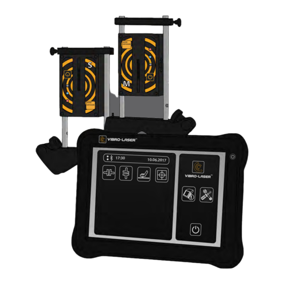
Page 10: System Description
SYSTEM DESCRIPTION SENSOR UNITS M and S ON/OFF button (hold for 2-3 seconds to turn o ) Mini USB port (for charging) Clamping bar with screw Charge indicator (illuminates green during charging then turns Connection indicator (illuminates blue when connects, blinks during transfer) ON indicator (illuminates red when ready for work, illuminates green... -
Page 11: Preparation For Work
PREPARATION FOR WORK Fix the sensor unit with the M label to the movable part of the machine, and then x the S-labeled sensor unit to the stationary. Mounting each sensor for each side as shown below. The sensor units should be xed with a shift (see the gure). Note! Fix the sensors at a reasonable distance from eachother not beyond 10m Place the v-bracket vertically on the shaft of the machine being... -
Page 12: Preliminary Works
(Fig. A) (Fig. B) (Fig. C) (Fig. D) Attention! M unit laser direction can be adjusted with the adjusting screw at the top of the unit. Normally, it is not required, but it may be needed if the distance between units is large. PRELIMINARY WORKS Before start of the alignment check for following: What are the alignment tolerances required? -
Page 13: Settings
Check for pipe strain; Check for end clearance between the shafts (axial alignment). SETTINGS Mount the sensor units on the shafts. Turn the S and M units on (the red LED indicator goes on). Turn the VIBRO-LASER software. Touch the Icon “Global settings”... - Page 14 Touch the Icon “Sensor units search” When connected, the indicators will illuminate in blue. Attention! After initial use the sensor units will be automatically connected by default. Choose Measurement Resolution. Choose units of measurement (millimeters or inches). Choose between metric and imperial measurement convention, and the necessary resolution (default setting is 0.01 mm or 0.4 mils).
-
Page 15: Sensor Unit Readings
Variation of the results might be caused by instability of measurement process. Try reducing the intensity of air movement between laser and the detector (e.G. By replacing the heat sources or closing doors). If the results are still instable, increase the lter value. Default setting is 1. Most common values are from 1 to 3. -
Page 16: Soft Foot
Otherwise the results of a precision alignment will be inne ective. The removal of the soft foot is impossible without any measuring devices. In your VIBRO-LASER embedded alignment program you are able to provide to identify and correct soft foot. - Page 17 Choose the bolt by touching the Icon First loosen the chosen bolt completely, then tighten it rmly. It is recommended to use a torque wrench for tightening. Save the measurement result by touching the “OK” Icon Repeat these actions for other bolts. Note! You can carry out new measurement at any time by touching the corresponding Icon.
- Page 18 Make the required corrections then check each foot once more. Note! Allowed values from 0mm to 0.06 mm...
-
Page 19: Horizontal Alignment
HORIZONTAL ALIGNMENT Touch the icon “Horizontal alignment” in main men Complete the alignment procedure step by step, following the arrow indicator. Note! You can backup to the horizontal alignment menu anytime to con rm your step. - Page 20 Insert the tolerance values according to the rotation rate of the machine. Touch the icon Insert the dimensions Touch the icon to insert the dimensions.
-
Page 21: Carry Out Measurements (9-3-12 Method)
The eld activates a calculator interface. To submit the inserted dimensions, touch Use the supplied tape measure for measuring: • Distance between the BARS CENTRES OF M and S UNITS • Distance between the center of coupling joint and the BAR CENTER of M unit •... - Page 22 Touch the Icon The rst measurement is registered in the table. To reset the data, touch the Icon Turn the shafts to the 3 o’clock. Tap the measurement icon The second measurement is registered in the table. Turn the shafts to the 12 o’clock...
- Page 23 Touch the measurement icon The third measurement is registered in the table. Touch the Icon Results of measurements...
- Page 24 This screen shows the misalignment values according to the coupling joint and the feet position (horizontal as well as vertical). Symbols on the left of the value indicate angular and parallel misalignment and bias directions, as well as indicates whether the values are within the allowable limits. Within the tolerance limits (green) Within the doubled tolerance limits (yellow) Beyond the doubled tolerance limits (red)
- Page 25 Note! Use VIBRO-LASER SHIMS to align the machine vertically. To adjust the shafts position horizontally, rotate the shafts to 3 or 9 o’clock. Use the displayed virtual levels for precise alignment. Adjust the machine’s horizontal position until the values are within the allowable limits according to the arrows next to the feet.
-
Page 26: Cut Angle Method
Note! Tighten the foot bolts crosswise with same force using a calibrated torque wrench to avoid changes of results! The alignment is complete To carry out the veri cation measurements touch Carry out the verification measurement using the Clock method. After the verification measurement the Horizontal Alignment menu is opened. - Page 27 Touch the Icon Start measuring from any point. Rotate shafts in the next position according to the animation. Touch the measurement Icon The rst measurement is registered in the table. Rotate shafts in the next position according to the animation.
- Page 28 Touch the Icon The second measurement is registered in the table. Rotate shafts in the next position according to the animation. Touch the Icon The third measurement is registered in the table. Attention! When taking measurements, rotate the shafts so the sectors do not overlap each other Note! For the best accurate maintain the sensors with maximum distance.
-
Page 29: Thermal Expansion Correction
THERMAL EXPANSION CORRECTION During the operation the equipment is exposed to various factors and forces. The most common in uence on alignment is change of the machine temperature which leads to the enlargement of a shaft and subsequent misalignment. This process is called thermal expansion or growth. To compensate the thermal expansion you need to make a correction for the expansion of the cold machine during its heating through out operation. - Page 30 When the results are received, the sign is shown, indicating that the thermal correction is made.
-
Page 31: Vertical Alignment
VERTICAL ALIGNMENT Vertical shafts alignment is carried out by moving the machine ange/coupling until the axes are coaxial enough to stay in the assigned limits. The system is able to work with an allowance table. Touch the Icon Complete the alignment procedure step by step, following the arrow indicator. Note! You can open the vertical alignment menu at anytime to verify your step... - Page 32 Insert the tolerance values according to the RPM of the machine. Touch the icon to insert the dimensions. VThe eld activates a calculator interface. To submit the inserted dimensions, touch Use a measuring tape for measuring: Distance between the BARS CENTERS OF M and S UNITS Distance between the center of coupling joint and the BAR CENTER of M unit Distance between the centers of outer bolts.
- Page 33 Touch the measurement icon The rst measurement is registered in the table. Rotate shafts in the next position according to the animation.
- Page 34 Touch the measurement icon The second measurement is registered in the table. Rotate shafts in the next position according to the animation. Touch the measurement icon The third measurement is registered in the table. Touch the button to get the measurement result The measurement results screen shows the misalignment values according to the coupling joint in both directions.
- Page 35 The table on the right contains bolts numbers with designation of shims required for eliminating misalignment. within the allowable limits (green) within the doubled allowable limits (yellow) beyond the doubled allowable limits (red) Symbols next to the socket joint repeat the limit readings. within the allowable limits within the doubled allowable limits beyond the doubled allowable limits...
- Page 36 To carry out the veri cation measurements touch Carry out the verification measurement. After the veri cation measurement the Vertical Alignment menu is opened. Save results by touching...
-
Page 37: Saving Data And Report Creation
SAVING DATA AND REPORT CREATION Note! The program has autosaving function: every time the program is started, the previous result is shown. To reset them, touch One of our system advantages is possibility to save, restore and edit the results of the alignment on any stage! Touch the icon to save alignment results Insert the name of the report with the... -
Page 38: Information
Note! Upload a previously saved report and continue alignment from where you stopped. To create a report touch You can edit the report header with your machine and company information using the touch screen and virtual keyboard. - Page 39 Options of report menu Print the repor Save the report as PDF Save the report as PDF...
-
Page 40: Information About System And Software
INFORMATION ABOUT SYSTEM AND SOFTWARE To see the system data, tap the button Vibro-laser instruments corporation thanks you for your business. Should you require support please go to www.Vibro-laser.Com... - Page 42 тм тм...
Need help?
Do you have a question about the VLSAT and is the answer not in the manual?
Questions and answers