Table of Contents
Advertisement
Quick Links
Advertisement
Table of Contents

Related Manuals for FMUser FM STL10 SERIES

Summary of Contents for FMUser FM STL10 SERIES
-
Page 1: User Manual
FM STL10 SERIES USER MANUAL - 1 -... - Page 2 STL10 FM STL TRANSMITTER / RECEIVER INTRODUCTION The STL10-xxT is a solid-state wideband FM Transmitter providing a continuously variable RF output form 0 to 25 watts into a 50 Ohm load at many frequency within the UHF/ VHF band in 10 kHz increments. The STL10-xxR receiver uses the same synthesized oscillator as the transmitter.
-
Page 3: Safety First
SAFETY FIRST! IMPORTANT: In order to avoid risks to personnel in the installation, utilization and maintenance of units, the following safety procedures and guidelines will be followed. Improper use or installation of this apparatus could cause serious damage to objects and people alike. -
Page 4: Technical Specifications
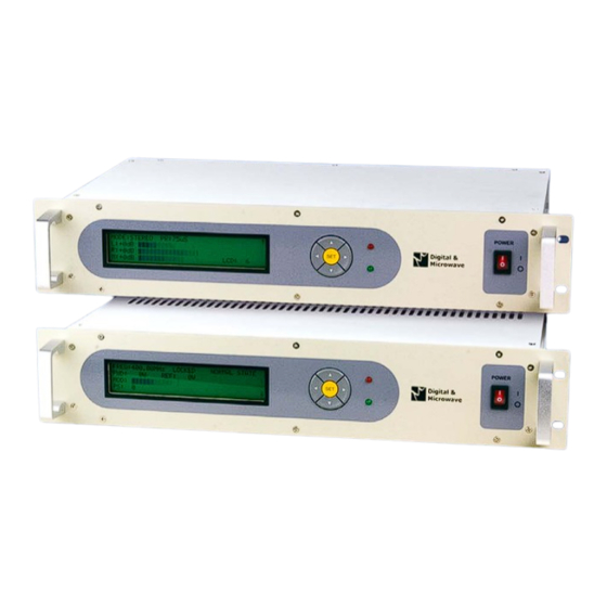
TECHNICAL SPECIFICATIONS TECHNICAL CHARACTERISTICS for TRANSMITTER Frequency range…………………... 200.00 to 220 MHz /240 to 260 MHz / 300 to 320 MHz / 320 to 340 MHz / 400 to 420 MHz / 460 to 470 MHz / or other frequency on demand. Output Power……………………….. - Page 5 FRONT PANEL All FMT-Series digital front panels are pretty similar; they all carry the LCD display and function keys for operation control. The power-on switch with internal mains signaling lamp is on the right. - 5 -...
-
Page 6: Rear Panel Connectors
REAR PANEL CONNECTORS AUDIO INPUT EXTERNAL 90~264V AC 50/60 Hz 80VA RIGHT 10-100000 Hz OUTPUT 50 OHM FUSE 3A/250V 20-100 KHz LEFT EARTH AUDIO OUTPUT MONITOR 90~264V AC 50/60 Hz 80VA RIGHT PHONE STEREO ANT. FUSE 3A/250V 20-100 KHz LEFT EARTH All STL input and out put are allocated on the rear panel. -
Page 7: Installation And Use
INSTALLATION AND USE STL TRANSMITTERS FOREWORD TO INSTALLATION Install the transmitter in a dry, vented, dust-free environment, with a mean temperature of +10~+35 °C. Do not install on surfaces or racks subjected to vibrations, external vibrations can impair S/N ratio. Connect your audio source using suitable cables and connectors. - Page 8 RF CONNECTION Connect the N type output connector, marked "RF OUT" to the antenna system with top-grade 50-ohm shielded cable. Note: Although most 50-ohm specified cable has enough power management capability, its power attenuation can be too high and may excessively lower the power available to the antenna.
- Page 9 Initially, the PLL requires sometime to lock onto your frequency. During this phase the LCD will display “UNLOCK” and “**INH** PLL UNLOCK” alarm. Once locked onto your frequency the display will show “LOCKED” and “NORMAL STATE”. At this point the transmitter will begin delivering power to your antenna. - 9 -...
- Page 10 SETTING FREQUENCY AND TRANSMIT POWER From the main menu, press “SET” for 3 seconds, the LCD will display the setup mode. You should see FREQ with the [ ***.**MHz ] in blocks. Use “▲” “▼” keys to change frequency, press and hold for fast forward, for fine tune press and release.
- Page 11 Use the “▲" “▼" keys to move to the next display parameter. Next, we will repeat the setup mode in the audio display, press “SET” for 3 seconds or until you see the [ ] blocks. The [ ] blocks will be in “MODE” area. Use the “▲" “▼" keys to change from Stereo to Mono, when you have selected stereo/mono press the “►”...
- Page 12 LF CONNECTION Pre-emphasis setting “PR:” Low frequency and stereo channel signals have to be adequately "pre-emphasized". For this purpose, select the setting “PR” and choose 0, 25, 50, and 75μs. Factory preset is 50μs. (Europe/Pacific/South America). USA requires 75μs. When using an external processor that employs pre-emphasis you must set the “PR”...
- Page 13 shown to the right; Impedance selection is silkscreened on the component mask of the board. LF audio mono or stereo input employ " XLR" female connectors, use balanced coaxial cable connected to pin 3(+) and pin 2(-). Connect the ground of the driving equipment to pin 1.
- Page 14 In the same way, when discussing the modulation, we will assume a 0dB signal produces 100% maximum modulation, i.e. 75 kHz deviation. There is no absolute world-wide standard regarding LF peak level as a modulation signal for a transmitter, nor for the mean deviation. Many Broadcasters use 0 or +6 dBm as LF peak level for 100% modulation, USA often uses +10 dBm.
- Page 15 The auxiliary channel level is much more difficult to be precisely set, due to the wider range of the continuously variable control, 18 dB vs. 4 dB. Nevertheless dB control is easy to be set when applying the nominal signal from an external generator, whose level is known, and regulating it to display the wanted modulation on the modulation meter.
- Page 16 The tendency to over process the audio signal is common with local broadcasting stations: some sort of processing is advisable and we recommend using a top grade multiband compressor but not as to compress the signal to a point that impairs the original dynamics.
-
Page 17: Operation
OPERATION Stereo Broadcasting with 2 Input Audio Channels: 1) Wire the XLR-type modulation input connectors, marked "Left" (channel) and "Right" (channel), to the output of the two channels from the mixer or stereo source. 2) Change "MODE" to "Stereo". Mono Broadcasting, from a monophonic audio source: 1) Wire the "right"... - Page 18 Mono or Stereo Broadcasting from Radio-Link Receiver or an External Encoder: 1) In this case, the signal is already multiplexed and pre-emphasized. Use the "External" or "Stereo" audio input. The signal skips the coding and filtering stage and therefore is not pre-emphasized. 2) Move "MODE"...
- Page 19 meter will never show a much greater value. Factory preset is 100kHz (+2.5dB). "MODE" Switch on "Mono " and “0dB” In this position, the audio circuit gain of the transmitter is slightly below unity (90%) and corresponds to the sensitivity obtainable in the stereo position, with pilot tone which allows for the remaining 10%.
- Page 20 STL RECIEVER FOREWORD TO INSTALLATION Install the RECIEVER in a dry, vented, dust-free environment, with a mean temperature of +10~+35 °C. Do not install on surfaces or racks subjected to vibrations, external vibrations can impair S/N ratio. Connect your audio source using suitable cables and connectors. The STL10 Series audio circuitry is similar to hi-fi equipment and should be installed and wired with the same attention;...
- Page 21 RF CONNECTION Connect the N type input connector, marked "ANT. in" from the antenna system with top-grade 50-ohm shielded cable. We suggest RG213 cable or RG58 cable can be used. Times Microwave, Cell Flex, Andrews all manufacture high quality low loss coax. POWER UP 1) Connect reciever to mains, check the ground.
- Page 22 SETTING FREQUENCY AND OTHER PARAMETERS If this is the first boot or you need to change the systems configuration, keeping press “◄” and ”►” button same time during power on. It will goes to service mode, once complete the LCD will look like this: You should see FREQ with the [ ***.**MHz ] in blocks.
- Page 23 Once you have set the frequency use the “◄” “►” keys to change to the next parameter. This will display the MODE with the STEREO in [STEREO ] blocks, use the “▲" “▼" keys to set the receive mode with STEREO or MONO. MUTE Use the “◄”...
- Page 24 AUDIO AND MPX OUTPUT LEVEL Use the “◄” “►” keys to change to the next parameter. This will display the L/R with the dB in [**dB ] blocks, use the “▲" “▼" keys to set your audio output level from -9 to +6 dB. Use the “◄” “►” keys to change MPX output level.
-
Page 25: General Conditions Of Sale
GENERAL CONDITIONS OF SALE All orders shall imply acceptance of the general conditions laid out herein 6- TRANSFER OF RISKS AND OWNERSHIP below. Where differences arise between the general conditions and the specific conditions stipulated in price quotations, the latter shall prevail. No 6.1 Risks shall be transferred to the purchaser as of dispatch of the goods, amendments to the present conditions shall be valid without written including goods sent carriage paid.
Need help?
Do you have a question about the FM STL10 SERIES and is the answer not in the manual?
Questions and answers