Table of Contents
Advertisement
Advertisement
Table of Contents

Related Manuals for ASROCK Fatal1ty B360M Performance


Summary of Contents for ASROCK Fatal1ty B360M Performance
-
Page 2: Copyright Notice
(including damages for loss of profits, loss of business, loss of data, interruption of business and the like), even if ASRock has been advised of the possibility of such damages arising from any defect or error in the documentation or product. - Page 3 If you require assistance please call ASRock Tel : +886-2-28965588 ext.123 (Standard International call charges apply) The terms HDMI™...
- Page 4 Fatal1ty Story Who knew that at age 19, I would be a World Champion PC gamer. When I was 13, I actually played competitive billiards in professional tournaments and won four or five games off guys who played at the highest level. I actually thought of making a career of it, but at that young age situations change rapidly.
- Page 5 LIVIN’ LARGE Since my first big tournament wins, I have been a “Professional Cyberathlete”, traveling the world and livin’ large with lots of International media coverage on outlets such as MTV, ESPN and a 60 Minutes segment on CBS to name only a few. It's unreal - it's crazy. I’m living a dream by playing video games for a living.
-
Page 6: Table Of Contents
-Ready Graphics Cards 2.7.2 Driver Installation and Setup M.2 WiFi/BT Module and Intel® CNVi (Integrated WiFi/BT) Installation Guide M.2_SSD (NGFF) Module Installation Guide (M2_1 and M2_2) 30 Chapter 3 Software and Utilities Operation Installing Drivers F-Stream ASRock Live Update & APP Shop... - Page 7 3.3.1 UI Overview 3.3.2 Apps 3.3.3 BIOS & Drivers 3.3.4 Setting Creative SoundBlaster Cinema5 ASRock RGB LED Chapter 4 UEFI SETUP UTILITY Introduction EZ Mode Advanced Mode 4.3.1 UEFI Menu Bar 4.3.2 Navigation Keys Main Screen OC Tweaker Screen Advanced Screen 4.6.1 CPU Configuration...
- Page 8 Security Screen 4.10 Boot Screen 4.11 Exit Screen...
-
Page 9: Chapter 1 Introduction
ASRock’s website without further notice. If you require technical support related to this motherboard, please visit our website for specific information about the model you are using. You may find the latest VGA cards and CPU support list on ASRock’s website as well. ASRock website http://www.asrock.com. -
Page 10: Specifications
1.2 Specifications Platform • Micro ATX Form Factor • Supports 8 Generation Intel® Core Processors (Socket 1151) • Digi Power design • 10 Power Phase design • Supports Intel® Turbo Boost 2.0 Technology Chipset • Intel® B360 Memory • Dual Channel DDR4 Memory Technology • 4 x DDR4 DIMM Slots • Supports DDR4 2666/2400/2133 non-ECC, un-buffered memory... - Page 11 Fatal1ty B360M Performance Series Graphics • Intel® UHD Graphics Built-in Visuals and the VGA outputs can be supported only with processors which are GPU integrated. • Supports Intel® UHD Graphics Built-in Visuals : Intel® Quick Sync Video with AVC, MVC (S3D) and MPEG-2 Full HW Encode1, Intel®...
- Page 12 • 1 x M.2 Socket (M2_2), supports M Key type 2230/2242/2260/2280 M.2 SATA3 6.0 Gb/s module and M.2 PCI Express module up to Gen3 x1 (8 Gb/s)** ** Supports Intel® Optane Technology (M2_1 only) ** Supports NVMe SSD as boot disks ** Supports ASRock U.2 Kit...
- Page 13 Fatal1ty B360M Performance Series Connector • 1 x COM Port Header • 1 x TPM Header • 1 x Chassis Intrusion and Speaker Header • 2 x RGB LED Headers * Support in total up to 12V/3A, 36W LED Strip • 1 x Addressable LED Header...
- Page 14 • ErP/EuP Ready (ErP/EuP ready power supply is required) * For detailed product information, please visit our website: http://www.asrock.com Please realize that there is a certain risk involved with overclocking, including adjusting the setting in the BIOS, applying Untied Overclocking Technology, or using third-party overclocking tools.
-
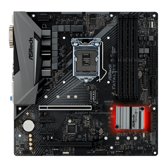
Page 15: Motherboard Layout
Fatal1ty B360M Performance Series 1.3 Motherboard Layout CPU_FAN1 CPU_FAN2/WP ATX12V1 USB 3.1 Gen2 T: USB3_TA_1 B: USB3_TC_1 USB 3.1 Gen1 T: USB3_3 B: USB3_4 CHA_FAN1/WP USB 2.0 Top: T: USB1 RJ-45 B: USB2 CHA_FAN2/WP PCIE1 Intel USB 3.1 Gen2 B360M Performance... - Page 16 No. Description ATX 12V Power Connector (ATX12V1) CPU Fan Connector (CPU_FAN1) 2 x 288-pin DDR4 DIMM Slots (DDR4_A1, DDR4_B1) 2 x 288-pin DDR4 DIMM Slots (DDR4_A2, DDR4_B2) CPU/Water Pump Fan Connector (CPU_FAN2/WP) RGB LED Header (RGB_LED2) Addressable LED Header (A_RGB_LED1) ATX Power Connector (ATXPWR1) USB 3.1 Gen1 Header (USB3_5_6) SATA3 Connector (SATA3_0)
-
Page 17: I/O Panel
Fatal1ty B360M Performance Series 1.4 I/O Panel No. Description No. Description PS/2 Mouse Port USB 2.0 Port (USB2) D-Sub Port USB 3.1 Gen1 Ports (USB3_3_4) LAN RJ-45 Port* USB 3.1 Gen2 Type-A Port (USB3_TA_1) Line In (Light Blue)** USB 3.1 Gen2 Type-C Port (USB3_TC_1) - Page 18 ** To configure 7.1 CH HD Audio, it is required to use an HD front panel audio module and enable the multi- channel audio feature through the audio driver. Please set Speaker Configuration to “7.1 Speaker”in the Realtek HD Audio Manager. Function of the Audio Ports in 7.1-channel Configuration: Port Function...
-
Page 19: Chapter 2 Installation
Fatal1ty B360M Performance Series Chapter 2 Installation This is a Micro ATX form factor motherboard. Before you install the motherboard, study the configuration of your chassis to ensure that the motherboard fits into it. Pre-installation Precautions Take note of the following precautions before you install motherboard components or change any motherboard settings. -
Page 20: Installing The Cpu
2.1 Installing the CPU 1. Before you insert the 1151-Pin CPU into the socket, please check if the PnP cap is on the socket, if the CPU surface is unclean, or if there are any bent pins in the socket. Do not force to insert the CPU into the socket if above situation is found. Otherwise, the CPU will be seriously damaged. - Page 21 Fatal1ty B360M Performance Series...
- Page 22 Please save and replace the cover if the processor is removed. The cover must be placed if you wish to return the motherboard for after service.
-
Page 23: Installing The Cpu Fan And Heatsink
Fatal1ty B360M Performance Series 2.2 Installing the CPU Fan and Heatsink... -
Page 24: Installing Memory Modules (Dimm)
2.3 Installing Memory Modules (DIMM) This motherboard provides four 288-pin DDR4 (Double Data Rate 4) DIMM slots, and supports Dual Channel Memory Technology. 1. For dual channel configuration, you always need to install identical (the same brand, speed, size and chip-type) DDR4 DIMM pairs. 2. - Page 25 Fatal1ty B360M Performance Series...
-
Page 26: Expansion Slots (Pci Express Slots)
2.4 Expansion Slots (PCI Express Slots) There are 4 PCI Express slots on the motherboard. Before installing an expansion card, please make sure that the power supply is switched off or the power cord is unplugged. Please read the documentation of the expansion card and make necessary hardware settings for the card before you start the installation. -
Page 27: Jumpers Setup
Fatal1ty B360M Performance Series 2.5 Jumpers Setup The illustration shows how jumpers are setup. When the jumper cap is placed on the pins, the jumper is “Short”. If no jumper cap is placed on the pins, the jumper is “Open”. -
Page 28: Onboard Headers And Connectors
2.6 Onboard Headers and Connectors Onboard headers and connectors are NOT jumpers. Do NOT place jumper caps over these headers and connectors. Placing jumper caps over the headers and connectors will cause permanent damage to the motherboard. System Panel Header Connect the power PLED+ PLED-... - Page 29 Fatal1ty B360M Performance Series Serial ATA3 Connectors These six SATA3 (SATA3_0: connectors support SATA see p.7, No. 10) data cables for internal (SATA3_1: storage devices with up to see p.7, No. 11) 6.0 Gb/s data transfer rate. (SATA3_2: If M2_2 is occupied by a see p.7, No.
- Page 30 1. High Definition Audio supports Jack Sensing, but the panel wire on the chassis must support HDA to function correctly. Please follow the instructions in our manual and chassis manual to install your system. 2. If you use an AC’97 audio panel, please install it to the front panel audio header by the steps below: A.
- Page 31 Fatal1ty B360M Performance Series ATX Power Connector This motherboard pro- (24-pin ATXPWR1) vides a 24-pin ATX power (see p.7, No. 8) connector. To use a 20-pin ATX power supply, please plug it along Pin 1 and Pin ATX 12V Power...
- Page 32 RGB LED Headers These two RGB headers are used (4-pin RGB_LED1) to connect RGB LED exten- (see p.7, No. 23) sion cable which allows users to choose from various LED light- (4-pin RGB_LED2) ing effects. (see p.7, No. 6) Caution: Never install the RGB LED cable in the wrong orienta- tion;...
-
Page 33: Tm Tm
Fatal1ty B360M Performance Series 2.7 CrossFireX and Quad CrossFireX Operation Guide This motherboard supports CrossFireX and Quad CrossFireX that allows you to install up to three identical PCI Express x16 graphics cards. 1. You should only use identical CrossFireX -ready graphics cards that are AMD certified. - Page 34 Step 3 Connect a VGA cable or a DVI cable to the monitor connector or the DVI connec- tor of the graphics card that is inserted to PCIE1 slot.
-
Page 35: Driver Installation And Setup
Fatal1ty B360M Performance Series 2.7.2 Driver Installation and Setup Step 1 Power on your computer and boot into OS. Step 2 Remove the AMD drivers if you have any VGA drivers installed in your system. The Catalyst Uninstaller is an optional download. We recommend using this utility to uninstall any previously installed Catalyst drivers prior to installation. -
Page 36: Wifi/Bt Module And Intel® Cnvi (Integrated Wifi/Bt) Installation Guide
2.8 M.2 WiFi/BT Module and Intel® CNVi (Integrated WiFi/BT) Installation Guide The M.2, also known as the Next Generation Form Factor (NGFF), is a small size and versatile card edge connector that aims to replace mPCIe and mSATA. The M.2 Socket (Key E) supports type 2230 WiFi/BT module and Intel®... - Page 37 Fatal1ty B360M Performance Series Step 3 Gently insert the WiFi/BT module or Intel® CNVi (Integrated WiFi/ BT) into the M.2 slot. Please be aware that the module only fits in one orientation. Step 4 Tighten the screw with a screwdriver to secure the module into place.
-
Page 38: M.2_Ssd (Ngff) Module Installation Guide (M2_1 And M2_2)
2.9 M.2_SSD (NGFF) Module Installation Guide (M2_1 and M2_2) The M.2, also known as the Next Generation Form Factor (NGFF), is a small size and versatile card edge connector that aims to replace mPCIe and mSATA. The Ultra M.2 Socket (M2_1) supports M Key type 2230/2242/2260/2280 M.2 PCI Express module up to Gen3 x4 (32 Gb/s). - Page 39 Fatal1ty B360M Performance Series Step 3 Move the standoff based on the module type and length. The standoff is placed at the nut location D by default. Skip Step 3 and 4 and go straight to Step 5 if you are going to use the default nut.
- Page 40 SD6PP4M-256G TEAM PCIe3 x4 TM8FP2240G0C101 TEAM PCIe3 x4 TM8FP2480GC110 Transcend SATA3 TS256GMTS400 Transcend SATA3 TS512GMTS600 PCIe3 x4 WDS256G1X0C-00ENX0 (NVME) PCIe3 x4 WDS512G1X0C-00ENX0 (NVME) For the latest updates of M.2_SSD (NFGG) module support list, please visit our website for details: http://www.asrock.com...
- Page 41 Fatal1ty B360M Performance Series M.2_SSD (NGFF) Module Support List (M2_2) Vendor Interface ADATA SATA3 AXNS330E-32GM-B ADATA SATA3 AXNS381E-128GM-B ADATA SATA3 AXNS381E-256GM-B ADATA SATA3 ASU800NS38-256GT-C ADATA SATA3 ASU800NS38-512GT-C Crucial SATA3 CT120M500SSD4 Crucial SATA3 CT240M500SSD4 Intel SATA3 Intel SSDSCKGW080A401/80G Kingston SATA3 SM2280S3...
-
Page 42: Chapter 3 Software And Utilities Operation
Chapter 3 Software and Utilities Operation 3.1 Installing Drivers The Support CD that comes with the motherboard contains necessary drivers and useful utilities that enhance the motherboard’s features. Running The Support CD To begin using the support CD, insert the CD into your CD-ROM drive. The CD automatically displays the Main Menu if “AUTORUN”... -
Page 43: F-Stream
Fatal1ty B360M Performance Series 3.2 F-Stream F-Stream is ASRock’s multi purpose software suite with a new interface, more new features and improved utilities. 3.2.1 Installing F-Stream F-Stream can be downloaded from ASRock Live Update & APP Shop. After the installation, you will find the icon “F-Stream“ on your desktop. Double-click the “F-Stream“... - Page 44 System Info View information about the system. *The System Browser tab may not appear for certain models. FAN-Tastic Tuning Configure up to five different fan speeds using the graph. The fans will automatically shift to the next speed level when the assigned temperature is met.
- Page 45 Fatal1ty B360M Performance Series Settings Configure ASRock F-Stream. Click to select "Auto run at Windows Startup" if you want F-Stream to be launched when you start up the Windows operating system.
-
Page 46: Asrock Live Update & App Shop
Double-click on your desktop to access ASRock Live Update & APP Shop utility. *You need to be connected to the Internet to download apps from the ASRock Live Update & APP Shop. 3.3.1 UI Overview Category Panel Hot News... -
Page 47: Apps
Fatal1ty B360M Performance Series 3.3.2 Apps When the "Apps" tab is selected, you will see all the available apps on screen for you to download. Installing an App Step 1 Find the app you want to install. The most recommended app appears on the left side of the screen. The other various apps are shown on the right. - Page 48 Step 3 If you want to install the app, click on the red icon to start downloading. Step 4 When installation completes, you can find the green "Installed" icon appears on the upper right corner. To uninstall it, simply click on the trash can icon *The trash icon may not appear for certain apps.
- Page 49 Fatal1ty B360M Performance Series Upgrading an App You can only upgrade the apps you have already installed. When there is an available new version for your app, you will find the mark of "New Version" appears below the installed app icon.
-
Page 50: Bios & Drivers
3.3.3 BIOS & Drivers Installing BIOS or Drivers When the "BIOS & Drivers" tab is selected, you will see a list of recommended or critical updates for the BIOS or drivers. Please update them all soon. Step 1 Please check the item information before update. Click on to see more details. -
Page 51: Setting
Fatal1ty B360M Performance Series 3.3.4 Setting In the "Setting" page, you can change the language, select the server location, and determine if you want to automatically run the ASRock Live Update & APP Shop on Windows startup. -
Page 52: Creative Soundblaster Cinema5
3.4 Creative SoundBlaster Cinema5 The SoundBlaster Cinema5, powered by the SBX Pro Studio technologies, is designed to bring the same great audio experience found in live performances, films, and recording studios to the PC. With this utility, you can easily enhance your audio environment in five modes, including Headphones, Speakers, Music, Movie, Game, Voice and Custom. -
Page 53: Asrock Rgb Led
Fatal1ty B360M Performance Series 3.5 ASRock RGB LED ASRock RGB LED is a lighting control utility specifically designed for unique individuals with sophisticated tastes to build their own stylish colorful lighting system. Simply by connecting the LED strip, you can customize various lighting schemes and patterns, including Static, Breathing, Strobe, Cycling, Music, Wave and more. - Page 54 Connecting the Addressable RGB LED Strip Connect your Addressable RGB LED strip to the Addressable LED Header (A_RGB_LED1) on the motherboard. A_RGB_LED1 1. Never install the RGB LED cable in the wrong orientation; otherwise, the cable may be damaged. 2. Before installing or removing your RGB LED cable, please power off your system and unplug the power cord from the power supply.
- Page 55 ASRock RGB LED Utility Now you can adjust the RGB LED color through the ASRock RGB LED utility. Download this utility from the ASRock Live Update & APP Shop and start coloring your PC style your way! Drag the tab to customize your preference.
-
Page 56: Chapter 4 Uefi Setup Utility
Chapter 4 UEFI SETUP UTILITY 4.1 Introduction This section explains how to use the UEFI SETUP UTILITY to configure your system. You may run the UEFI SETUP UTILITY by pressing <F2> or <Del> right after you power on the computer, otherwise, the Power-On-Self-Test (POST) will continue with its test routines. -
Page 57: Ez Mode
Fatal1ty B360M Performance Series 4.2 EZ Mode The EZ Mode screen appears when you enter the BIOS setup program by default. EZ mode is a dashboard which contains multiple readings of the system’s current status. You can check the most crucial information of your system, such as CPU speed, DRAM frequency, SATA information, fan speed, etc. -
Page 58: Advanced Mode
4.3 Advanced Mode The Advanced Mode provides more options to configure the BIOS settings. Refer to the following sections for the detailed configurations. To access the EZ Mode, press <F6> or click the "EZ Mode" button at the upper right corner of the screen. -
Page 59: Navigation Keys
Fatal1ty B360M Performance Series 4.3.2 Navigation Keys Use < > key or < > key to choose among the selections on the menu bar, and use < > key or < > key to move the cursor up or down to select items, then press <Enter>... -
Page 60: Main Screen
4.4 Main Screen When you enter the UEFI SETUP UTILITY, the Main screen will appear and display the system overview. My Favorite Display your collection of BIOS items. Press F5 to add/remove your favorite items. -
Page 61: Oc Tweaker Screen
Fatal1ty B360M Performance Series 4.5 OC Tweaker Screen In the OC Tweaker screen, you can set up overclocking features. Because the UEFI software is constantly being updated, the following UEFI setup screens and descriptions are for reference purpose only, and they may not exactly match what you see on your screen. -
Page 62: Long Duration Maintained
Intel Turbo Boost Technology Intel Turbo Boost Technology enables the processor to run above its base operating frequency when the operating system requests the highest performance state. Intel Speed Shift Technology Enable/Disable Intel Speed Shift Technology support. Enabling will expose the CPPC v2 interface to allow for hardware controlled P-states. - Page 63 DRAM Clock Choose a frequency to override to clock delay for memory training. DRAM Clock controls memory training only if ASRock Timing Optimization is disabled. Primary Timing CAS# Latency (tCL) The time between sending a column address to the memory and the beginning of the data in response.
- Page 64 RAS to RAS Delay (tRRD_S) The number of clocks between two rows activated in different banks of the same rank. Write to Read Delay (tWTR_L) The number of clocks between the last valid write operation and the next read command to the same internal bank.
- Page 65 Fatal1ty B360M Performance Series tRDRD_dd Configure between module read to read delay. tRDWR_sg Configure between module read to write delay. tRDWR_dg Configure between module read to write delay. tRDWR_dr Configure between module read to write delay. tRDWR_dd Configure between module read to write delay.
- Page 66 RTL Init Value Configure round trip latency init value for round trip latency training. IO-L Init Value Configure IO latency init value for IO latency training. RTL (CH A) Configure round trip latency for channel A. RTL (CH B) Configure round trip latency for channel B. IO-L (CH A) Configure IO latency for channel A.
- Page 67 Fatal1ty B360M Performance Series ODT WR (B2) Configure the memory on die termination resistors' WR for channel B2. ODT NOM (A1) Use this to change ODT (CH A1) Auto/Manual settings. The default is [Auto]. ODT NOM (A2) Use this to change ODT (CH A2) Auto/Manual settings. The default is [Auto].
-
Page 68: Advanced Setting
MRS tCL Configure the tCL for Memory MRS MR0. MRS tWRtRTP Configure the tWRtRTP for Memory MRS MRC. MRS tCWL Configure the tCWL for Memory MRS MR2. MRS tCCD_L Configure the tCL for Memory MRS MR6. Advanced Setting ASRock Timing Optimization... -
Page 69: Voltage Configuration
Fatal1ty B360M Performance Series Configure the fast path through the MRC. Realtime Memory Timing Configure the realtime memory timings. [Enabled] The system will allow performing realtime memory timing changes after MRC_DONE. Command Tristate Configure the Command Tristate Support. Exit On Failure Configure the Exit On Failure for MRC training steps. - Page 70 Load User Default Load previously saved user defaults. Save User UEFI Setup Profile to Disk It helps you to save current UEFI settings as an user profile to disk. Load User UEFI Setup Profile from Disk You can load previous saved profile from the disk.
-
Page 71: Advanced Screen
Fatal1ty B360M Performance Series 4.6 Advanced Screen In this section, you may set the configurations for the following items: CPU Configuration, Chipset Configuration, Storage Configuration, Super IO Configura- tion, ACPI Configuration, USB Configuration and Trusted Computing. Setting wrong values in this section may cause the system to malfunction. -
Page 72: Cpu Configuration
4.6.1 CPU Configuration Intel Hyper Threading Technology Intel Hyper Threading Technology allows multiple threads to run on each core, so that the overall performance on threaded software is improved. Active Processor Cores Select the number of cores to enable in each processor package. CPU C States Support Enable CPU C States Support for power saving. -
Page 73: Intel Virtualization Technology
Fatal1ty B360M Performance Series CFG Lock This item allows you to disable or enable the CFG Lock. CPU Thermal Throttling Enable CPU internal thermal control mechanisms to keep the CPU from overheat- ing. Intel Virtualization Technology Intel Virtualization Technology allows a platform to run multiple operating systems and applications in independent partitions, so that one computer system can function as multiple virtual systems. -
Page 74: Chipset Configuration
4.6.2 Chipset Configuration Primary Graphics Adapter Select a primary VGA. Above 4G Decoding Enable or disable 64bit capable Devices to be decoded in Above 4G Address Space (only if the system supports 64 bit PCI decoding). VT-d Intel® Virtualization Technology for Directed I/O helps your virtual machine monitor better utilize hardware by improving application compatibility and reliability, and providing additional levels of manageability, security, isolation, and I/O performance. - Page 75 Fatal1ty B360M Performance Series PCIE4 Link Speed Select the link speed for PCIE4. PCI Express Native Control Select Enable for enhanced PCI Express power saving in OS. PCIE ASPM Support This option enables/disables the ASPM support for all CPU downstream devices.
- Page 76 Configure deep sleep mode for power saving when the computer is shut down. Restore on AC/Power Loss Select the power state after a power failure. If [Power Off] is selected, the power will remain off when the power recovers. If [Power On] is selected, the system will start to boot up when the power recovers.
-
Page 77: Storage Configuration
Fatal1ty B360M Performance Series 4.6.3 Storage Configuration SATA Controller(s) Enable/disable the SATA controllers. SATA Aggressive Link Power Management SATA Aggressive Link Power Management allows SATA devices to enter a low power state during periods of inactivity to save power. It is only supported by AHCI mode. -
Page 78: Super Io Configuration
4.6.4 Super IO Configuration Serial Port Enable or disable the Serial port. Serial Port Address Select the address of the Serial port. -
Page 79: Acpi Configuration
Fatal1ty B360M Performance Series 4.6.5 ACPI Configuration Suspend to RAM Select disable for ACPI suspend type S1. It is recommended to select auto for ACPI S3 power saving. PS/2 Keyboard Power On Allow the system to be waked up by a PS/2 Keyboard. - Page 80 USB Mouse Power On Allow the system to be waked up by an USB mouse.
-
Page 81: Usb Configuration
Fatal1ty B360M Performance Series 4.6.6 USB Configuration Legacy USB Support Enable or disable Legacy OS Support for USB 2.0 devices. If you encounter USB compatibility issues it is recommended to disable legacy USB support. Select UEFI Setup Only to support USB devices under the UEFI setup and Windows/Linux operating systems only. -
Page 82: Trusted Computing
4.6.7 Trusted Computing Security Device Support Enable or disable BIOS support for security device. -
Page 83: Tools
Fatal1ty B360M Performance Series 4.7 Tools UEFI Tech Service Contact ASRock Tech Service if you are having trouble with your PC. Please setup network configuration before using UEFI Tech Service. Instant Flash Save UEFI files in your USB storage device and run Instant Flash to update your UEFI. -
Page 84: Network Configuration
Network Configuration Use this to configure internet connection settings for Internet Flash. Internet Setting Enable or disable sound effects in the setup utility. UEFI Download Server Select a server to download the UEFI firmware. -
Page 85: Hardware Health Event Monitoring Screen
Fatal1ty B360M Performance Series 4.8 Hardware Health Event Monitoring Screen This section allows you to monitor the status of the hardware on your system, including the parameters of the CPU temperature, motherboard temperature, fan speed and voltage. Fan Tuning Measure Fan Min Duty Cycle. - Page 86 and assign a respective fan speed for each temperature. CPU Fan 2 Temp Source Select a fan temperature source for CPU Fan 2. CPU Fan 2 Step Up Set the value of CPU Fan 2 Step Up. CPU Fan 2 Step Down Set the value of CPU Fan 2 Step Down.
- Page 87 Fatal1ty B360M Performance Series Chassis Fan 2 Temp Source Select a fan temperature source for Chassis Fan 2. Chassis Fan 2 Step Up Set the value of Chassis Fan 2 Step Up. Chassis Fan 2 Step Down Set the value of Chassis Fan 2 Step Down.
-
Page 88: Security Screen
4.9 Security Screen In this section you may set or change the supervisor/user password for the system. You may also clear the user password. Supervisor Password Set or change the password for the administrator account. Only the administrator has authority to change the settings in the UEFI Setup Utility. Leave it blank and press enter to remove the password. -
Page 89: Boot Screen
Fatal1ty B360M Performance Series 4.10 Boot Screen This section displays the available devices on your system for you to configure the boot settings and the boot priority. Fast Boot Fast Boot minimizes your computer's boot time. In fast mode you may not boot from an USB storage device. - Page 90 Full Screen Logo Enable to display the boot logo or disable to show normal POST messages. AddOn ROM Display Enable AddOn ROM Display to see the AddOn ROM messages or configure the AddOn ROM if you've enabled Full Screen Logo. Disable for faster boot speed. Boot Failure Guard Message If the computer fails to boot for a number of times the system automatically restores the default settings.
- Page 91 Fatal1ty B360M Performance Series Launch Storage OpROM Policy Select UEFI only to run those that support UEFI option ROM only. Select Legacy only to run those that support legacy option ROM only. Select Do not launch to not execute both legacy and UEFI option ROM.
-
Page 92: Exit Screen
4.11 Exit Screen Save Changes and Exit When you select this option the following message, “Save configuration changes and exit setup?” will pop out. Select [OK] to save changes and exit the UEFI SETUP UTILITY. Discard Changes and Exit When you select this option the following message, “Discard changes and exit setup?”... -
Page 93: Contact Information
Contact Information If you need to contact ASRock or want to know more about ASRock, you’re welcome to visit ASRock’s website at http://www.asrock.com; or you may contact your dealer for further information. For technical questions, please submit a support request form at https://event.asrock.com/tsd.asp... -
Page 94: Declaration Of Conformity
13848 Magnolia Ave, Chino, CA91710 Phone/Fax No: +1-909-590-8308/+1-909-590-1026 hereby declares that the product Product Name : Motherboard Fatal1ty B360M Performance Series Model Number : Conforms to the following speci cations: FCC Part 15, Subpart B, Unintentional Radiators Supplementary Information: is device complies with part 15 of the FCC Rules. Operation is subject to the... - Page 95 EU Declaration of Conformity For the following equipment: Motherboard (Product Name) Fatal1ty B360M Performance Series / ASRock (Model Designation / Trade Name) ASRock Incorporation (Manufacturer Name) 2F., No.37, Sec. 2, Jhongyang S. Rd., Beitou District, Taipei City 112, Taiwan (R.O.C.) (Manufacturer Address) EMC —Directive 2014/30/EU (from April 20th, 2016)
Need help?
Do you have a question about the Fatal1ty B360M Performance and is the answer not in the manual?
Questions and answers