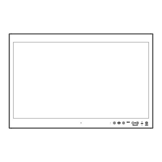
Hatteland HD 15T22 MMD Series Technical Manual

Hatteland HD 15T22 MMD Series Technical Manual

Serial/ethernet/usb communication control interface scom, series x g2 maritime multi display mmd, series x multi vision display mvd
Table of Contents

Advertisement

T E C H N I C A L
M A N U A L
Serial/Ethernet/USB Communication Control Interface (SCOM)
Applies for Series X G2 Maritime Multi Display (MMD) product range:
Series X Multi Vision Display (MVD) product range
HD 15T22 MMD-xxx-xxxx
HD 17T22 MMD-xxx-xxxx
HD 19T22 MMD-xxx-xxxx
HD 24T22 MMD-xxx-xxxx
HD 26T22 MMD-xxx-xxxx
HD 32T22 MVD-xxx-xxxx
HD 55T22 MVD-xxx-xxxx
Updated: 08 Jan 2018
Created: 6644/363
Approved: 6644
Please visit www.hatteland-display.com for the latest electronic version of this manual.
Hatteland Display AS, Eikeskogvegen 52, N-5570 Aksdal, Norway
Tel: (+47) 4814 2200 - mail@hatteland-display.com - www.hatteland-display.com
Technical Manual SCOM Series X MMD G2 & MVD Series
Doc Id: INB100018-6 (Rev 04)

Advertisement

Table of Contents
loading

Summary of Contents for Hatteland HD 15T22 MMD Series

  • Page 1 Updated: 08 Jan 2018 Doc Id: INB100018-6 (Rev 04) Created: 6644/363 Approved: 6644 Please visit www.hatteland-display.com for the latest electronic version of this manual. Hatteland Display AS, Eikeskogvegen 52, N-5570 Aksdal, Norway Tel: (+47) 4814 2200 - mail@hatteland-display.com - www.hatteland-display.com...
  • Page 2 Copyright © 2017 Hatteland Display AS Eikeskogvegen 52, N-5570 Aksdal, Norway. All rights are reserved by Hatteland Display AS. This information may not, in whole or in part, be copied, photocopied, reproduced, translated or reduced to any electronic medium or machine- readable form without the prior written consent of Hatteland Display AS.
  • Page 3: Table Of Contents

    Contents Contents ....................3 Serial/Ethernet/USB Communication (SCOM) Interface ...... 5 Introduction ................... 5 Serial / USB Interface Configuration ....................5 Ethernet Interface Configuration ......................7 Cables ..............................7 Electrical Interface..........................7 SCOM Introduction..........................9 Data Rates ............................9 Data Format Serial Mode ........................9 Message Format ..........................
  • Page 4 Contents SCOM Section: Interface ..............32 "CBR" - COM Ports Baudrate Configuration ..................32 "BAK" - Broadcast Acknowledgement ....................33 SCOM Section: ECDIS ............... 34 "DLN" - Download package ........................ 34 "DL?" - Request Number of packages available ................35 "CAL"...
  • Page 5: Serial/Ethernet/Usb Communication (Scom) Interface

    Serial/Ethernet/USB Communication (SCOM) Interface Introduction This document defines the electrical interface, serial data format, and communication protocols of the Serial Communication Control Interface (SCOM). The purpose of this interface is to enable a computer application to control one or more units. Unit refer to display product. Serial / USB Interface Configuration The serial / USB interface can have different configurations, selected by the OSD menu.
  • Page 6 Serial/Ethernet/USB Communication (SCOM) Interface Illustration: Broadcast Message: Timing 2 Illustration: Broadcast Message: Timing 3 User computer is linked with three units via the RS485 bus. These three units are assigned in address: 0, 1, 3. At the beginning, User computer broadcast a message to all connected units. Assuming all of them finish receiving at the same time, then the address ‘0’...
  • Page 7: Ethernet Interface Configuration

    Serial/Ethernet/USB Communication (SCOM) Interface Illustration: Addressed Message In the scenario that user computer sends out the message to specific address, the unit which owns the matching address will respond immediately, while the other keep silent. Ethernet Interface Configuration The Ethernet/LAN/Network interface are selected by the OSD menu. The configuration is defined as follows: Ethernet One computer controls max 16 units via Automatic IP or Fixed IP through port 10001.
  • Page 8 Serial/Ethernet/USB Communication (SCOM) Interface - Compatible connectors: • SCOM RS-422/485 : Terminal Block Connector 3.81, non-isolated • SCOM RS-232 : D-SUB 9P (female), non-isolated • Ethernet : RJ45 (female) • USB : USB 2.0 (Type A, female) Only one communication port is active. The selection of active communication is determined by OSD menu setting item.
  • Page 9: Scom Introduction

    Serial/Ethernet/USB Communication (SCOM) Interface SCOM Introduction The SCOM commands specified in this document are of the same structure as older versions of Hatteland Display SCOM commands for other products. This format will be explained in the following sections. Data Rates The unit is configured to transmit and receive data at 9600 bits/second (Serial mode) or via standard Ethernet 10/100/1000Mbps connection through port 10001.
  • Page 10: Address (Addr)

    Serial/Ethernet/USB Communication (SCOM) Interface ADDR Address (ADDR) The address byte is not used in this implementation of the SCOM protocol and is ignored. I.e. all possible bytes are accepted. Message Commands and Queries (CMD) Contents The command can be one of the following values and consists always of 3 bytes in positions 2,3,4: Byte 2 Byte 3 Byte 4 ASCII Description...
  • Page 11: Data Length (Len)

    Serial/Ethernet/USB Communication (SCOM) Interface Data Length (LEN) This single byte defines the length of DATA in the message in bytes. The maximum value for this field is 74 bytes (0x4A in HEX). The minimum value is 0 bytes (0x00 in HEX). IHCHK Inverse Header Checksum (IHCHK) This single byte is a simple 8-bit checksum of the header data, message bytes 0 to 5 on which a bit-wise inversion...
  • Page 12: Scom Section: Brightness

    Serial/Ethernet/USB Communication (SCOM) Interface SCOM Section: Brightness In SCOM protocol, there are five brightness related commands, which define the backlight/LED brightness value and their adjustable range. LCD Brightness : Full range of LCD backlight. System Brightness : Full range of system level brightness. User Brightness : Variation range of User level.
  • Page 13: Bri" - Minimum Backlight Brightness

    Serial/Ethernet/USB Communication (SCOM) Interface "BRI" - Minimum Backlight Brightness The command is used to set the minimum brightness of backlight. It defines the lower bound of the visual brightness range. For example, if we set BRI to 10%, the minimum achievable brightness is 10% in PWM step curve. Byte # 0x07 0xFF...
  • Page 14: Brm" - Maximum Backlight Brightness

    Serial/Ethernet/USB Communication (SCOM) Interface "BRM" - Maximum Backlight Brightness The command is used to set the maximum brightness of backlight. It defines the upper bound of the visual brightness range. For example, if we set BRM to 90%, the maximum achievable brightness is 90% in PWM step curve. Byte # 0x07 0xFF...
  • Page 15: Brt" - Brightness Control

    Serial/Ethernet/USB Communication (SCOM) Interface "BRT" - Brightness Control This command controls the display backlight brightness setting. If BRT is 100%, the user can adjust the user brightness (BRU) from 0-100%. If the BRT is set to 60%, the visual brightness is set to 60%. The user can adjust the user brightness (BRU) from 0-100% within the 60% set by BRT.
  • Page 16: Brl" - Brightness Led

    Serial/Ethernet/USB Communication (SCOM) Interface "BRL" - Brightness LED The command is used to set the keypad's LED brightness manually. This can only control the Brightness LED if the GBF command is set to not follow backlight. Byte # 0x07 0xFF 0x42 0x52 0x4C...
  • Page 17: Bru" - User Brightness Control

    Serial/Ethernet/USB Communication (SCOM) Interface "BRU" - User Brightness Control This command controls the user brightness control (BRU). If BRT is 100%, the user can adjust the user brightness (BRU) from 0-100%. If the BRT is set to 60%, the visual brightness is set to 60%. The user can adjust the user brightness (BRU) from 0-100% within the 60% set by BRT.
  • Page 18: Scom Section: Glass Display Controlâ„¢ (Gdc)

    Serial/Ethernet/USB Communication (SCOM) Interface SCOM Section: Glass Display Control™ (GDC) Commands related to configure and control the GDC behaviour. "GMB" - Buttons Minimum Brightness This command controls the minimum brightness level of the button LEDs of keypad and GDC system. The BRL level can never be lower than this limit no matter which "GBF mode"...
  • Page 19: Gbf" - Keypad Brightness Auto Follow

    Serial/Ethernet/USB Communication (SCOM) Interface "GBF" - Keypad Brightness auto follow This command controls if the keypad brightness level will follow the LCD backlight brightness, follow the brightness sensor, or if the keypad brightness shall be manually set by BRL command. If the GBF command is set to follow the LCD backlight brightness, or the light sensor brightness, the result is scaled by the BRL.
  • Page 20 Serial/Ethernet/USB Communication (SCOM) Interface Notes for the "GBF" command 1: Auto Follow LCD backlight level - Use System brightness (BRI, BRM, BRT) and User Brightness (BRU) to calculate the LCD Brightness Step. - Find the position in LCD brightness PWM curve and generate proper PWM to LCD. - Convert the position of LCD PWM curve to Keypad PWM Curve based on gamma.
  • Page 21 Serial/Ethernet/USB Communication (SCOM) Interface 3: Auto follow Light Sensor - Use System brightness (BRI, BRM, BRT) and User Brightness (BRU) to calculate the LCD Brightness Step. - Find the position in LCD brightness PWM curve and generate proper PWM to LCD. - Convert the position of Light sensor value to Keypad PWM Curve based on gamma.
  • Page 22: Lis" - Read Ambient Light Sensor

    Serial/Ethernet/USB Communication (SCOM) Interface "LIS" - Read Ambient Light Sensor This command is used to read the value of the ambient light sensor. This value reads the Channel 0 of the ambient light sensor in system with keypad and embedded light sensor of GDC in GDC system. Example: Read Light Sensor: 0x07...
  • Page 23: Odm" - Outdoor Mode

    Serial/Ethernet/USB Communication (SCOM) Interface "ODM" - Outdoor Mode This command shall set the GDC outdoor mode. The outdoor mode will add 5 second delay to the GDC buttons. However this 5s press is not needed again if 5s does not elapse since last button usage (If one button has been held for more than 5s, any button will respond instantly.
  • Page 24: Rec" - Recall Gdc

    Serial/Ethernet/USB Communication (SCOM) Interface "REC" - Recall GDC This command will recall the GDC registers to default values. = Restored to value in Factory Configuration file. = Restore to value in Factory Configuration file. = Restore to value 0x00. = Restore to value 0xFF. Byte # 0x07 0xFF...
  • Page 25: Pot" - Backlight Control Interface Selection

    Serial/Ethernet/USB Communication (SCOM) Interface "POT" - Backlight Control Interface selection This command is used to select which HW control method will be used in user backlight control (BRU). The available control methods: SCOM command, GDC keypad and analog potentiometer. Byte # 0x07 0xFF 0x50...
  • Page 26: Scom Section: Buzzer

    Serial/Ethernet/USB Communication (SCOM) Interface SCOM Section: Buzzer Commands to control the internal Buzzer, or External Buzzer (if available). If External Buzzer is available, commands apply for both internal and external Buzzer at the same time. "BZZ" - Buzzer Control This command is used to control buzzer on/off signal. Length of DATA is 1. Byte # 0x07 0xFF...
  • Page 27: Scom Section: Service

    Serial/Ethernet/USB Communication (SCOM) Interface SCOM Section: Service Commands to review Service related information available for the unit. "SWI" - Main Software Version Query This query is sent to the unit in order to get the uC software version ID. Length of DATA must be zero. The DATA field will be an ASCII text string indicating the software version.
  • Page 28: Typ" - Type/Model Number Query

    Serial/Ethernet/USB Communication (SCOM) Interface "TYP" - Type/Model Number Query This query is sent to the unit in order to identify the unit type by its model number / part number. Length of DATA shall be zero. The unit will reply to this command with an ACK attention code. The DATA field should be translated to an ASCII text string which indicates the specified Type/Model Number, e.g: "HD55T22MVDMA1TOGP".
  • Page 29: Csi" - Read Customer Service Id

    Serial/Ethernet/USB Communication (SCOM) Interface "CSI" - Read Customer Service ID This command is used to read the Customer Service ID. The length of DATA is zero bytes. The command should not return bytes with value 0xFF. Example: Read "CSI" from LPC: 0x07 0xFF 0x43...
  • Page 30: Tmp" - Read Temperature Sensor

    Serial/Ethernet/USB Communication (SCOM) Interface "TMP" - Read Temperature Sensor The unit features temperature sensor that measures the temperature inside. The TMP command can be used to read the current sensor temperature. The length of DATA shall be 1 or 2 and contain the following: Data length is 1, return the value from temperature sensor 0x00 Byte # 0x07...
  • Page 31: Ver" - Read Specific Type

    Serial/Ethernet/USB Communication (SCOM) Interface "VER" - Read Specific Type This command is used to read the specific Type segment in Type Number. The returned value is the three characters from pos 8 to 10 in stored Type Number. If there is no type number stored, return 0 byte. For example, if the type number is "HD55T22MVDMA1AAAAAAA", VER should return "MVD"...
  • Page 32: Scom Section: Interface

    Serial/Ethernet/USB Communication (SCOM) Interface SCOM Section: Interface Commands to control the global settings that affects communication/protocol behaviour. "CBR" - COM Ports Baudrate Configuration This command is used to configure the baudrate on COM ports. The command will select between RS232 and RS485 port.
  • Page 33: Bak" - Broadcast Acknowledgement

    Serial/Ethernet/USB Communication (SCOM) Interface "BAK" - Broadcast Acknowledgement This command is used to set turn on/off broadcast acknowledgement of the received message on RS485/422 port. The purpose of adding this command is to simplify the message processing on computer side. Setting will be changed after sending an answer.
  • Page 34: Scom Section: Ecdis

    Serial/Ethernet/USB Communication (SCOM) Interface SCOM Section: ECDIS Commands for downloading ECDIS Color Table files (if stored in memory and performed by factory). "DLN" - Download package This command shall be sent to request a specific data packet stored in the microcontroller. The DATA field shall contain the packet number being requested;...
  • Page 35: Dl?" - Request Number Of Packages Available

    Serial/Ethernet/USB Communication (SCOM) Interface "DL?" - Request Number of packages available This command is used to request the number of packets available for download. The DATA field of the command shall contain no data when requesting size of active ECDIS. Byte # 0x07 0xFF...
  • Page 36: Cal" - Calibration Brightness Level

    Serial/Ethernet/USB Communication (SCOM) Interface "CAL" - Calibration brightness level This command inquire the GDC calibration Level. For units that are ECDIS calibrated from factory, the LED pattern (ECDIS) indicates that the backlight/brightness is at calibrated level. Byte # 0x07 0xFF 0x43 0x41 0x4C...
  • Page 37: Scom Section: Factory

    Serial/Ethernet/USB Communication (SCOM) Interface SCOM Section: Factory Commands related to configuration of global Factory preset. "RCF" - Recall Factory Configuration This command will recall the original copy of factory configuration. The user copy of configuration will be replaced and overwritten completely. Affected Configuration Type: 1: Brightness.
  • Page 38: Scom Section: Power

    Serial/Ethernet/USB Communication (SCOM) Interface SCOM Section: Power Commands related to configuration of global Power settings. "PWR" - Power On/Off/Sleep unit This command is used to power on/off the unit or put the unit in sleep mode. Byte # 0x07 0xFF 0x50 0x57 0x52...
  • Page 39: Scom Section: Video Scaler

    Serial/Ethernet/USB Communication (SCOM) Interface SCOM Section: Video Scaler Commands related to configuration of the internal Video Controller logic and behaviour including function related to the On Screen Display Menu (OSD). "VUR" - Read User Configuration from Video Scalar The command reads the user saved configuration from video scalar. The configuration saves OSD settings. The user configuration table size is 256 bytes.
  • Page 40: Vus" - Store User Configuration To Video Scalar

    Serial/Ethernet/USB Communication (SCOM) Interface "VUS" - Store User Configuration to Video Scalar The command write the user configuration to video scalar. The user configuration table size is 256 bytes. Note: the command is passed to VS only. The read process will be divided into 4 packets (64 bytes in each). Byte # 0x07 0xFF 0x56 0x55 0x53 0x42 IHCHK...
  • Page 41: Scom Section: Osd Control Functionality

    Note: Review the differences in the "MCC Commands List" on the following pages for details. Reference: Engineering Change Notification (ECN): http://www.hatteland-display.com/mails/31_2017_ecn.html GEV1 = Reference to Series X Maritime Multi Display (MMD) - Generation 1 (G1) - HD xxT21xxD models. GEV2 = Reference to Series X Maritime Multi Display (MMD) - Generation 2 (G2) - HD xxT22xxD models and Multi Vision Displays (MVD) - HD xxT22 MVD models.
  • Page 42: Mcc" - Osd Control Functionality

    Serial/Ethernet/USB Communication (SCOM) Interface "MCC" - OSD Control Functionality Each MCC command will specify a OSD Command ID in the first data byte. The OSD Command ID represents an OSD menu setting item or internal function. Byte # 0 7+LEN 8+LEN 0x07 0xFF 0x4D 0x43...
  • Page 43: Mcc Commands List

    Serial/Ethernet/USB Communication (SCOM) Interface MCC Commands List NOTE: A char between the ' ' indicate an ASCII value. Example '1' = 0x31. A complete HEX, ASCII, BIN and Character table overview are available in the APPENDIX chapter. Some commands have footnotes, see references at the end of this table. Function Data Description...
  • Page 44 Serial/Ethernet/USB Communication (SCOM) Interface Function Data Description GEV2 GEV1 Differences OSD lock mode 0x8D, Set OSD mode = normal / lock / reset '0' - normal (default) ‘0’ – normal (default) Same as GEV1 n | 'r' | 'R' | '?' / query '1' - FULL Protect ‘1’...
  • Page 45 Serial/Ethernet/USB Communication (SCOM) Interface Function Data Description GEV2 GEV1 Differences Communication mode 0x99, Select Communication mode = value / '0' - RS232 (Default) ‘0’ – RS232 (Default) Only difference is add new communication mode n | 'r' | 'R' | '?' reset / query '1' - Ethernet ‘1’...
  • Page 46 Serial/Ethernet/USB Communication (SCOM) Interface Function Data Description GEV2 GEV1 Differences Second source select 0xA7, Select input second = value / reset / 0x00 - DVI-I_1 0x30 - DVI1-1 Different Input ID between GEV1 and GEV2 n | 'r' | 'R' | '?' query 0x01 - DVI-I_2 0x31 - DVI1-2...
  • Page 47 Serial/Ethernet/USB Communication (SCOM) Interface Function Data Description GEV2 GEV1 Differences 4th source select 0xAE, Select input fourth = value / reset / query 0x00 - DVI-I_1 New command in GEV2. Only applicable for n | 'r' | 'R' | '?' 0x01 - DVI-I_2 HD 32 inch and HD 55 inch 0x02 - DVI3...
  • Page 48 Serial/Ethernet/USB Communication (SCOM) Interface Function Data Description GEV2 GEV1 Differences Loading the user default 0xD8, Loading all parameter to user default '0' - fail '0' - fail Same as GEV1 value (n = '1' to '5' correspond to User1 '1' - success '1' - success to Uesr5, and '0' is read Default) Swap Main &...
  • Page 49 Serial/Ethernet/USB Communication (SCOM) Interface Function Data Description GEV2 GEV1 Differences Touch Power Mode 0x73, 0xFF - "Always Active" (Default) New command in GEV2 0xFE - "Only active when unit is on n | 'r' | 'R' | '?' and has a valid input signal" 0x00 - "Only active if selected source has a valid input signal"...
  • Page 50 Serial/Ethernet/USB Communication (SCOM) Interface Function Data Description GEV2 GEV1 Differences External Power Button 0x74, *[3] - See comment '0' - Disabled (Default) New command in GEV2 n | 'r' | 'R' | '?' '1' - Enabled Picture Direction 0x75, '0' - 0 degrees (default) New command in GEV2 n | 'r' | 'R' | '?' '1' - 180 degrees...
  • Page 51: Comments To Mcc Command Table

    Serial/Ethernet/USB Communication (SCOM) Interface Comments to MCC Command table *[1] Power Plan - VGA buffer and USB in Off Mode: Enabled: When this setting is selected and computer is turned off is must enter "Completely off" mode Off: When this setting is selected and computer is turned off is must enter "Off" mode. *[2] Power Plan - LAN in off/Sleep mode: Enabled: When this setting is selected and computer is turned off (in "Off", "Completely Off"...
  • Page 52: Operational Requirements

    Serial/Ethernet/USB Communication (SCOM) Interface Operational Requirements The following sections define the operational requirements. Serial Message Failure If serial messages stop being transmitted or are corrupt, the unit will remain at the last commanded brightness. Periodic Messages Commands shall be transmitted to the unit at a repetition no faster than 4 Hz. Sending Multiple Commands / Command Queue To ensure all commands are transmitted and executed successfully on the unit, a delay between each command in the queue shall be at least 500ms.
  • Page 53: Unit Response And Addresses

    Serial/Ethernet/USB Communication (SCOM) Interface Unit Response and Addresses When individual unit addressing is supported by an installed configuration of units in a RS-485 (for units that support it) system, a separate ACK or NAK message for each unit will be transmitted providing each unit's individual address in response to any broadcast addressed Command.
  • Page 54 This page left intentionally blank...
  • Page 55: Appendixes

    Appendixes...
  • Page 56: Hex, Ascii, Bin And Character Table

    HEX, ASCII, BIN and Character table Character/Symbol Description 0x00 00000000 Null terminator / character / End of string 0x01 00000001 Start of Heading 0x02 00000010 Start of Text 0x03 00000011 End of Text 0x04 00000100 End of Transmission 0x05 00000101 Enquiry 0x06 00000110...
  • Page 57 HEX, ASCII, BIN and Character table Character/Symbol Description 0x33 00110011 Three 0x34 00110100 Four 0x35 00110101 Five 0x36 00110110 0x37 00110111 Seven 0x38 00111000 Eight 0x39 00111001 Nine 0x3A 00111010 Colon 0x3B 00111011 Semicolon 0x3C 00111100 < Less than (or open angled bracket) 0x3D 00111101 Equals...
  • Page 58 HEX, ASCII, BIN and Character table Character/Symbol Description 0x66 01100110 Lowercase f 0x67 01100111 Lowercase g 0x68 01101000 Lowercase h 0x69 01101001 Lowercase i 0x6A 01101010 Lowercase j 0x6B 01101011 Lowercase k 0x6C 01101100 Lowercase l 0x6D 01101101 Lowercase m 0x6E 01101110 Lowercase n...
  • Page 59 HEX, ASCII, BIN and Character table Character/Symbol Description 0x99 10011001 ™ Trade mark sign 0x9A 10011010 š Latin small letter S with caron 0x9B 10011011 › Single right-pointing angle quotation mark 0x9C 10011100 œ Latin small ligature oe 0x9D 10011101 (no visible character) 0x9E 10011110...
  • Page 60 HEX, ASCII, BIN and Character table Character/Symbol Description 0xCC 11001100 Ì Latin capital letter I with grave 0xCD 11001101 Í Latin capital letter I with acute 0xCE 11001110 Î Latin capital letter I with circumflex 0xCF 11001111 Ï Latin capital letter I with diaeresis 0xD0 11010000 Ð...
  • Page 61: C# / Pseudo Ethernet/Tcp Code Example

    C# / Pseudo Ethernet/TCP Code example // Create SCOM package byte[] cmd = enc.GetBytes("BRT"); byte[] data = byte[1] { 0x99 }; // 60% brightness COMMessage message = COMMessage(cmd, data); // Transmitting SCOM package to TCP SendTCPCommand(message); private Byte[] SendTCPCommand(COMMessage commessage) // Creating new TCPclient TcpClient tcpClient =...
  • Page 62: Revision History

    Revised wrong command example (CBR), page 32 Revised wrong command example (VUS), page 40 Added new command “MOD”, page 41 Revised MCC table (added note to Brightness Control) and added Differences GEV1 vs GEV2, page 43-51 - reference: http://www.hatteland-display.com/mails/31_2017_ecn.html IND100332-8...
  • Page 63 IND100332-8...
  • Page 64 w ww .hat tel and-di s p l ay . com...

Table of Contents