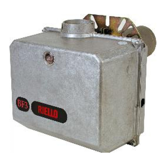
Riello 40BF Installation & Operating Manual

Riello 40BF Installation & Operating Manual

Single stage operation oil burners

Advertisement

Installation & Operating Manual
Single stage operation oil burners
RETROFIT APPLICATIONS ONLY
If this burner is being installed in a packaged unit (ie. burner comes with a boiler or furnace), follow
the installation and set-up instructions supplied with the heating unit, as settings may differ from
WARNING
those shown in this manual.
- The following pages contain information, descriptions and diagrams for the proper installation
and wiring of the burner. Please read carefully before attempting final installation.
- This manual is to remain with the final installation designation. It is the installer's responsibility to en-
sure that the burner installation and operation instructions mentioned in this manual are followed and
operated within local code authority limits.
This burner is not equipped for 2 line operation.
For 2 line operation order: part # C7001025 for BF3, C7001026 for BF5.
CODE
3729010
3729110
BF
MODEL
BF3
BF5
C6505027 - 20015900 (3) - 07/2014
TYPE
290T
291T

Advertisement

Table of Contents
loading

Summary of Contents for Riello 40BF

  • Page 1 Installation & Operating Manual Single stage operation oil burners RETROFIT APPLICATIONS ONLY If this burner is being installed in a packaged unit (ie. burner comes with a boiler or furnace), follow the installation and set-up instructions supplied with the heating unit, as settings may differ from WARNING those shown in this manual.
  • Page 2 The burner settings used in this manual were obtained under laboratory conditions and may vary from those obtained in the actual installation of the burner. Combustion results must be verified using proper combustion test equipment. Riello will not be responsible for the improper ATTENTION installation or set-up of the appliance.
  • Page 3: Table Of Contents

    APPLICATION FIELD WIRING - RIELLO 530 SE/C 24 VPRIMARY CONTROL.......
  • Page 4: Package Contents List

    PACKAGE CONTENTS LIST Your Riello 40 BF burner should include the following parts. Please check to make sure all parts are present before be- ginning the installation. Quantity Description Code Burner chassis with cover 3729010 - 3729110 Gasket 2567340 2621854...
  • Page 5: Technical Data

    3250 rpm Run Current 2.2 AMP Capacitor 12.5 Microfarads 260V Pump pressure 100 to 200 PSI Primary control RIELLO 530 SE/C - RIELLO 530 SE/C 24 V Ignition transformer 8kV 16mA BURNER AND MOUNTING FLANGE DIMENSIONS Model Inches 9 13/16...
  • Page 6: Mounting The Burner To Boiler Or Furnace

    MOUNTING THE BURNER TO THE BOILER OR FURNACE There are two possible methods to mount the burner, depending on the individual application. These are: 1) Universal flange bolted to Boiler/Furnace unit. 2) Universal flange mounted to optional Pedestal mount, where flange mounting direct to appliance is not possible. Pedestal kit must be ordered separately.
  • Page 7: Electrical Connections

    The burner may be controlled using either a DIRECT LINE VOLTAGE control circuit (120V AC 60 cycle) OR a LOW VOLTAGE control (24V AC 60 cycle) using models Riello or Honeywell R8038A 24v relays or a LOW VOLTAGE THERMOSTAT INPUT (T-T).
  • Page 8: Application Field Wiring

    APPLICATION FIELD WIRING All the installation, maintenance and disassembly operations MUST be carried out with the electric- ity supply disconnected. DANGER The installation of the burner must be carried out by qualified personnel, as indicated in this manual and in compliance with the standards and regulations of the laws in force. WARNING Earth Ground...
  • Page 9: Application Field Wiring - Riello 530 Se/C 24 Vprimary Control

    APPLICATION FIELD WIRING - RIELLO 530 SE/C 24V PRIMARY CONTROL DIRECT LINE LOW VOLTAGE VOLTAGE 120 V 120 V FUSE 15A FUSE 15A LINE SAFETY LINE SAFETY SWITCH SWITCH OPERATING LIMIT SWITCH 24V OPERATING SAFETY SAFETY LIMIT SWITCH LIMIT SWITCH...
  • Page 10: Installation/Removal Of Drawer Assembly

    INSTALLATION/REMOVAL OF DRAWER ASSEMBLY Removal: A) Loosen off oil delivery tube nut from pump. B) Loosen SCREW (3), and then unplug CON- TROL BOX (1) by carefully pulling it back and then up. C) Remove the AIR TUBE COVER PLATE (5) by loosening the retaining SCREW (4) (Two SCREWS –...
  • Page 11: Oil Line Connections

    D i r e c t c o n n e c t i o n o f N P T threads to the pump will dam- age the pump body. Riello manometers and vacuum gauges do not require any D7521 adapters, and can be safely connected to the pump ports.
  • Page 12: Two Line (Lift System)

    TWO LINE (LIFT SYSTEM) (Accessory package required) If a two-line system is required, install the By-pass plug. The by-pass plug is installed in the return port of the pump. A 2.5-mm hexagonal key is to be used to install the plug. DO NOT use an inch size hexagonal key;...
  • Page 13: Pump Purge

    PUMP PURGE NOTE: To protect the pump gears, it is advisable to lubricate the pump prior to purging a lift system. Apply oil through the VACUUM PORT (C). A) SINGLE LINE (GRAVITY FEED SYSTEM) I. Loosen the bleeder valve (A) until oil flows out. Tighten the bleeder valve securely and startburner.
  • Page 14: Combustion Chamber Pressure Chart

    COMBUSTION CHAMBER PRESSURE CHART BURNER OUTPUT VS CHAMBER PRESSURE CHART (GPH) BURNER OUTPUT 0.50 0.75 1.00 1.25 1.50 1.75 D7525 The firing rate was obtained considering a room temperature of 68 °F and an atmospheric pressure of 394 “wc (approx. 0 ft above sea level), with the combustion head adjusted. WARNING BURNER START-UP CYCLE Normal...
  • Page 15: Burner Adjustment Tables - Burner Setup Chart

    1.35 X 60/80° Actual input values given in above table are based on zero (0) chamber pressure, fired in Riello Canada Inc. Test Lab DIN (small) test boiler (chamber length 17”, chamber diameter of 11”). Input values calculated using pump pres- sures listed above in the set-up table.
  • Page 16: A Typical Layout For Bf Burner Intake Air

    A TYPICAL LAYOUT FOR BF BURNER INTAKE AIR A) Use an approved air intake kit. B) Always keep intake air run to the minimum. C) Maximum intake air run of 4 (inch) diameter, flexible or rigid type of venting = 100í D) Reduce intake air length by 10’...
  • Page 17: Trouble Shooting Chart

    TROUBLE SHOOTING CHART Thermostat is calling for heat Burner is not running Reset Control Box Burner Starts Burner Does Not Start Test for 120Vac Supply at sub-base between L(P) & N or terminals #3 & 5 120 Vac No Voltage •...
  • Page 18: Exploded Spare Parts List

    EXPLODED SPARE PARTS LIST 20015900...
  • Page 19: Spare Parts List

    SPARE PARTS LIST CODE DESCRIPTION CODE DESCRIPTION • 3020270 BURNER BACK COVER OPTIONAL • • • 3020271 BURNER BACK COVER C7001084 AL 1009 POST PURGE DEVICE KIT • • • • 3007077 CRUSHABLE METAL WASHER 3/8” ID C5283000 ELECTRICAL FITTING •...
  • Page 20 SPARE PARTS LIST CODE DESCRIPTION CODE DESCRIPTION • • 3948876 VERY SHORT 3” COMBUSTION HEAD 3948877 8 7/8” COMBUSTION HEAD • • 3948976 VERY SHORT 3” COMBUSTION HEAD 3948975 8 7/8” COMBUSTION HEAD • • 3006968 TURBULATOR DISC 3006968 TURBULATOR DISC •...
  • Page 21: Burner Start-Up List

    35 Pond Park Rd. 2165 Meadowpine Blvd. Hingham, MA 02043 Mississauga,On L5H 3R2 Phone: 781-749-8292 Phone: 905-542-0303 Toll Free: 800-992-7637 Toll Free: 800-387-3898 Fax: 781-740-2069 Fax: 905-542-1525 BURNER START- UP FORM * Burner S/N. or Model: Appliance: Installer name: Company: Installation date: Address: Phone:...
  • Page 24 RIELLO S.p.A. I-37045 Legnago (VR) Tel.: +39.0442.630111 http:// www.riello.it http:// www.riello.com RIELLO BURNERS NORTH AMERICA 1-800-4-RIELLO 35 Pond Park Road 2165 Meadowpine Blvd Hingham, Massachusetts, 1-800-474-3556 Mississauga, Ontario U.S.A. 02043 Canada L5N 6H6 http://www.riello.ca Subject to modifications...

This manual is also suitable for:

3729010Bf3290t3729110291tBf5

Table of Contents