
Related Manuals for Loup Electronics Weighlog 100


Summary of Contents for Loup Electronics Weighlog 100
- Page 1 Loup Electronics Weighlog 100 Onboard Weighing System User Guide Calibration and Operation Issue Date 1/2007...
-
Page 3: Service And Technical Support
Service and Technical Support PLEASE CONTACT YOUR NEAREST DISTRIBUTOR If unknown Contact Loup Electronics 2960 North 38th Street Lincoln, NE. 68504 Phone: 402-464-7131 Fax: 402-464-7104 Toll Free: 877-489-5687 © Copyright Loup Electronics Inc. 2007... -
Page 4: Table Of Contents
Contents 1. Overview 2. Maintaining Accuracy 2.1 Machine Requirements 2.2 Lifting Procedure 3. Initial Setup 3.1 Selecting Channel 3.2 Check/Change Display Readout 3.3 Weighing Methods 3.3.1 Dynamic Weighing 3.3.2 Static Weighing 3.4 Check/Change Weighing Modes 4. Check/Set Zero Weight 4.1 Check Zero Weight 4.2 Set Zero Weight 5. -
Page 5: Overview
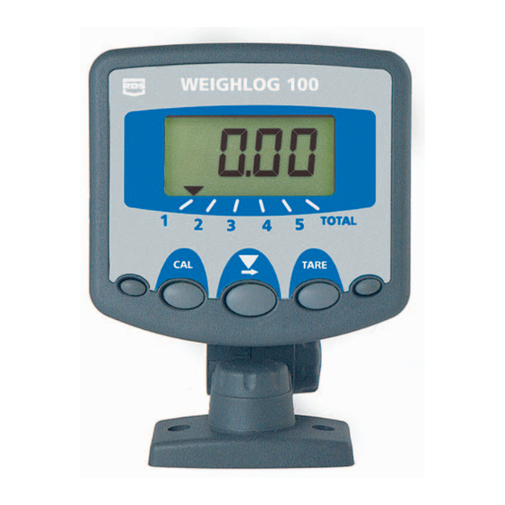
Overview The Weighlog 100 is intended for use on skid-steer loaders, backhoe loaders and small wheel loaders. It measures, displays and records the net weight lifted, normally based on sensing the lift system hydraulic pressure. Pressure sensing is problematic on certain types of equipment due to the design of the hydraulic system. In these instances strain sensing technology may be used instead. - Page 6 Overview The front panel has 5 buttons. Only the center 3 are used on the Weighlog 100. Enter Calibration Set empty bucket Mode weight to zero Select Channel Display units The instrument can display up to 9990 tons, or 99,990 lbs. depending on mode selected.
-
Page 7: Maintaining Accuracy
2 - Maintaining Accuracy The Weighlog translates pressure (or strain) to weight by means of a calibration factor programmed into the instrument. The accuracy of the system depends to some extent on the following: 2.1 Machine Requirements Operation Temperature: Always allow the machine and the hydraulics to warm up to the normal operating temperature before weighing. -
Page 8: Selecting Channel
Select Channel 1-Total 3.2 Check/Change Display Readout The Weighlog 100 can be set to read Tons "Eur" setting or lbs "USA" setting. The default setting is tons. If lbs readout is desired follow the steps shown below. Use the center arrow button and scroll to the "Total" channel To change weight readout. -
Page 9: Weighing Methods
3 - Initial Setup 3.3 Weighing Methods There are two weighing methods Dynamic "Dyn" or Static "StAt" both are explained below. 3.3.1 Dynamic Weighing Dynamic weighing means that the load is weighed without stopping the lift. The load is lifted up above the reference/direction sensors. Dynamic weighing can give consistant results without significantly slowing down the loading cycle, but does require the operator to be smooth and consistant with the lifts. -
Page 10: Check Zero Weight
4 - Check/Set Zero Weight 4.1 Check Zero Weight You should check the zero weight of the bucket regularly as part of the daily operating routine. ALWAYS check the zero weight if the machine has been left idle for some time and has cooled down. Checking the zero weight before the machine has warmed up some may result in false readings do to the oil being cold. -
Page 11: Set Zero Weight
4 - Check/Set Zero Weight 4.2 Set Zero Weight The bucket should be zeroed if the weight reading for an empty bucket is more than 20 lbs. Ensure the hydraulic system is up to operating temerature. It may be necessary to lift and lower the bucket a few times to warm up the hydraulic system. -
Page 12: Weight Calibration
5 - Calibration 5.1 Weight Calibration Accurate results from the Weighlog can only be achieved if the calibration procedure has been carried out carefully and in the correct sequence. You must set the zero weight of the empty bucket or forks and enter a weight calibration factor for each channel to be used. -
Page 13: Calibration Procedure
5 - Calibration 5.3 Calibration Procedure 1. Decide which attachment or product applies to which channel. This can be noted on the chart provided at the back of this manual. 2. Decide whether Dynamic or Static weighing will be used. Select the desired channel and set to correct weighing mode (Section 3.3). -
Page 14: Calibration Example
5 - Calibration 5.4 Calibration Example Calibrating a skid steer loader with a capacity of 3000 lbs. 1. Set the inital calibration number to 1.500. 2. A bucket load is weighed and the Weighlog reading is 2500 lbs. The known weight of the bucket load is 2100 lbs. 3. -
Page 15: Reset Channels
6 - Reset Channels/Total 6.1 Reset Channels Channels 1 thru 5 can be reset independently. 1. Select the correct channel 1 thru 5 2. Press and hold the remote enter button for 5 seconds. The display will flash 5 times and then reset to 0. This does not affect the TOTAL channel. - Page 16 Press and hold all three center buttons and switch the power on. If the instrument can recover itself, it will perform a short self test routine and return to the normal display. If not contact your local Loup Electronics dealer. NOTE: All calibration settings, sub-totals, grand total and weighing units will be reset to the factory default settings.
- Page 17 8 - Troubleshooting 8.0 Troubleshooting Symptom Possible Problem Correction Head unit does not Magnet is not close enough to Adjust sensor and/or magnet "Beep" when bucket the Reference/Direction Sensors. to within 1/4" to 1/2" maximum. is lifted. Reference and Direction Sensors Sensor relationship must be improperly installed.
- Page 18 8 - Troubleshooting 8.0 Troubleshooting Symptom Possible Problem Correction Accuracy Incorrect bucket position. Bucket must be rolled back completly before each lift. Incorrect calibration number. Most 100 applications will have a Cal. No of 1.0-4.0 make sure decimal point is in correct place.
- Page 19 J-Box. Check head unit cable and connections in the J-Box. If red LED in J-Box is lit and all connections are good contact dealer for assistance. Loup Electronics, Inc. 2960 North 38th St. Lincoln, NE. 68504 Phone: 402-464-7131 Fax: 402-464-7104 Toll Free: 877-489-5687 www.loupelectronics.com...
- Page 20 9 - Notes 9 - Notes Channel Attachment/Product Weighing Mode Cal. Factor Page 18...
Need help?
Do you have a question about the Weighlog 100 and is the answer not in the manual?
Questions and answers