
Related Manuals for HART 275


Summary of Contents for HART 275
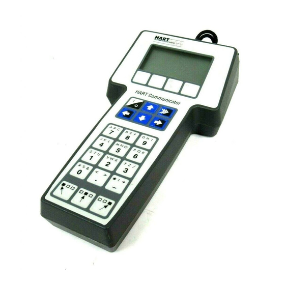
- Page 1 MAN 4275A00 PN: 00275-8026-0001 English July 2000 P r o d u c t D i s c o n t i n u e d ® HART Communicator...
- Page 2 For equipment service needs, contact the nearest product representative. Rosemount and SMART FAMILY are registered trademarks of Rosemount Inc. MINIGRABBER is a trademark of Pomona Electronics. HART is a registered trademark of the HART Communication Foundation. Fisher-Rosemount 8301 Cameron Road Austin, TX 78754 USA...
-
Page 3: Table Of Contents
Alphanumeric and Shift Keys ............1-8 Using the Fast Select Feature........... 1-8 Using Shift Keys for Data Entry..........1-9 Getting to Know the HART Communicator........1-9 Software Icons ................ 1-10 Learning the Menu Structure........... 1-11 Reviewing Installed Devices ........... 1-12 Main Menu.................. - Page 4 Customizing the Hot Key Menu..........1-31 Adding Options to the Hot Key Menu........1-31 Deleting Options from the Hot Key Menu........ 1-33 The HART Communicator and the Year 2000 ........ 1-34 Editing the Date............... 1-34 Servicing the HART Communicator ..........1-35 Calibrating the HART Communicator........
- Page 5 Menu Trees ............... 3-1 Introduction..................3-1 Model 54pH/ORP Transmitter ............3-2 Model 333 HART® Tri-Loop Converter ..........3-3 Model 644 Temperature Transmitter..........3-4 Model 1151 Pressure Transmitter ............ 3-5 Model 2081C Conductivity Transmitter ..........3-6 Model 2081pH Transmitter............... 3-7 Model 2088 Pressure Transmitter ............ 3-8 Model 2090 Pressure Transmitter ............
- Page 6 Model ProBarTM DP Flowmeter ............ 3-34 Model ProBarTM UC Flowmeter ............ 3-35 Model Tri-20/9000 Oval Flowmeter ..........3-36 Model WC3000 Oxygen Analyzer ..........3-37 HART Communicator Messages ........A-1 Specifications and Ordering Information ......B-1 Functional Specifications..............B-1 Performance Specifications.............. B-2 Physical Specifications..............
- Page 7 1-3. Connecting to the Transmitter Comm Terminals......1-3 1-4. Connecting the HART Communicator to the Loop...... 1-3 1-5. Connecting the HART Communicator with the Load Resistor..1-4 1-6. HART Communicator Alphanumeric and Shift Keys....1-8 1-7. Quickly Accessing Menus............1-8 1-8.
- Page 8 1-39. Variable Display Option............. 1-33 1-40. Deleting a Hot Key Option............1-33 1-41. Date Menu................1-34 1-42. HART Communicator Exploded View........1-35 1-43. Battery Pack Removal............... 1-36 1-44. Memory Module Replacement..........1-38 1-45. Data Pack 100 Installation and Removal........1-39 2-1.
-
Page 9: The Hart ® Communicator
4–20 mA. Because the total high- frequency signal voltage added to the loop amounts to zero, communication to and from a HART-compatible device does not disturb the 4–20 mA signal. LIQUID CRYSTAL DISPLAY (LCD) FUNCTION KEYS... -
Page 10: Hart Communicator Connections
HART COMMUNICATOR CONNECTIONS The HART Communicator can interface with a transmitter from the control room, the instrument site, or any wiring termination point in the loop through the rear connection panel (Figure 1-2). To interface, connect the HART Communicator with the appropriate connectors in parallel with the instrument or load resistor. -
Page 11: Connecting To The Transmitter Comm Terminals
NOTE: For the HART Communicator to function properly, a minimum of 250 ohms resistance must be present in the loop. The HART Communicator does not measure loop current directly. Figure 1-3 and Figure 1-4 illustrate typical wiring connections between the HART Communicator and any compatible device. -
Page 12: Connecting The Hart Communicator With The Load Resistor
WARNING Explosions can result in death or serious injury. Before connecting the HART Communicator in an explosive atmosphere, make sure the instruments in the loop are installed in accordance with intrinsically safe or nonincendive field wiring practices. For intrinsically safe CSA and FM wiring connections, see Appendix C. -
Page 13: Liquid Crystal Display (Lcd)
Use this key to power up and power off the HART Communicator. When you power up the Communicator, it automatically searches for a HART-compatible device on the 4-20 mA loop. If a device is not found, the Communicator displays the message “No Device Found. Press OK..” Press the OK ‘F4’... -
Page 14: Up Arrow Key
Hot Key Use this key to quickly access important, user-defined options when connected to a HART-compatible device. When the HART Communicator is turned off, press the Hot Key to automatically power up and display your predefined Hot Key menu. When powered up online, press the Hot Key to immediately display the Hot Key menu. - Page 15 In menus providing access to the Home menu, the label appears HOME above the F3 key. When the label displays, press F3 to return directly HOME to the Online menu. Press (F3) to return to the screen from which BACK was pressed.
-
Page 16: Alphanumeric And Shift Keys
Three shift keys enable use of the upper row of characters on each alphanumeric key. FIGURE 1-6. HART Communicator Alphanumeric and Shift Keys. Using the Fast Select Feature From within any menu, you can select available options in two ways: 1) you can use the up and down arrow keys and the select key to access available options, 2) you can use the fast select feature. -
Page 17: Using Shift Keys For Data Entry
GETTING TO KNOW THE HART COMMUNICATOR The HART Communicator is generally used in two environments — offline (not connected to a device) and online (connected to a device). The first menu displayed when you power up the Communicator is different for offline and online. -
Page 18: Software Icons
øø Online Menu Main Menu FIGURE 1-8. Powering Up Offline or Online. Software Icons The HART Communicator menus display icons that represent specific keys on the keypad. Figure 1-9 shows examples of these. HART communication: Blinking indicates ongoing communications (HART messages are presently being transmitted or received). -
Page 19: Learning The Menu Structure
Learning the Menu Structure The following steps show you how to power up the Communicator offline, move through the menu structure, and then turn off the Communicator: Turn the HART Communicator on. Access the Utility menu by pressing three times... -
Page 20: Reviewing Installed Devices
4. Review the different manufacturers and models to determine the installed HART-compatible devices in your Communicator. MAIN MENU If the HART Communicator is powered up when it is not connected to a device, the first menu to appear after the “Device Not Found” message is the Main menu (Figure 1-10). -
Page 21: Offline Menu
New Configuration and Saved Configuration. Figure 1-11 shows a menu tree for the Offline functions. A HART-compatible device does not have to be connected to use the offline options, except when sending saved configuration data to a connected device. -
Page 22: New Configuration (Offline)
5. Select a device revision; the From Blank Template menu (Figure 1-13) displays. If you are unsure of the device revision, connect the HART Communicator to the device and determine its device revision level. You can access this information from the Online menu>Device Setup>Detailed Setup>Device Information. -
Page 23: From Blank Template Menu
FIGURE 1-13. From Blank Template Menu. The following options are available from the From Blank Template menu: Mark all flags all configurable variables to be sent to a HART-compatible device. Configuration variables are those that appear when you edit variables in the configuration using the Edit Individually option. -
Page 24: Save As... Menu
NOTE: Configurations created offline in the HART Communicator will not transfer to Asset Management Solutions (AMS) software; however, ‘Full’ configurations saved from a field device to a HART Communicator may be uploaded to AMS. Configurations saved as ‘Full’ from an online device may also be transferred directly to AMS. -
Page 25: Saved Configuration Menu (Offline)
You can access configuration data already stored in your Communicator through the offline Saved Configuration menu. To access configuration data stored in your HART Communicator: 1. Press 1 on the Main menu to access the Offline menu. 2. Press 2 from the Offline menu, and the Saved Configuration menu screen displays (Figure 1-18). -
Page 26: Saved Configuration Menu (Data Pack Contents)
you entered with Sort by picking characters from the device Tag, Descriptor, or Name. When setting up a filter, you can use the period (.) to replace a single character of any value or the asterisk (*) to replace zero or more alphanumeric characters of any value. -
Page 27: Online Menu
The Online menu displays the name of the device on the first line of the LCD. You have complete functionality for a specific device only when that device description is present in the HART Communicator. If the DD is not present in the HART Communicator, contact your nearest service representative. - Page 28 When the DD for a specific device is not available, your HART Communicator provides a generic interface. This generic interface enables you to perform functions common to all HART-compatible devices. Figure 1-22 shows the Generic Online menu tree. The Online (Generic) menu is the first menu in the generic interface. This...
-
Page 29: Generic Online Menu Tree
3 Loop Test 1. Analog Output 4 D/A Trim 4 Detailed Setup 5 Scaled D/A Trim 3 Output Condition 1 Poll Address 2. HART Output 2 Number of Request Preambles 1 Model 2 Tag 3 Date 4 Descriptor 5 Message... -
Page 30: Frequency Device Menu
From the Main menu, press to access the Utility menu (Figure 1-24). The Utility menu provides access to functions that affect only the operation of the HART Communicator. FIGURE 1-24. Utility Menu. Configure Communicator Menu From the Utility menu, press 1 to access the Configure Communicator menu (Figure 1-25). -
Page 31: Polling Menu
Use the Polling options to configure your HART Communicator to automatically search for all or specific connected devices. The HART protocol allows you to communicate with multiple HART devices on a single twisted pair of wires over leased telephone lines. -
Page 32: Contrast Menu
ENTER Configure Communicator menu displays. Off Time Menu Off Time is the amount of time that elapses before your HART Communicator turns off automatically when not in use. Use the following steps to set the automatic turn off option: YZ / 1. -
Page 33: Ignore Diagnostics Menu
Communicator is turned off. Ignore Diagnostics Menu The HART Communicator is designed to display diagnostic messages from a connected device. The Ignore diagnostics option allows you to specify the number of ignored messages, extending the time between displayed messages. -
Page 34: System Information Menu
1-32). FIGURE 1-32. Listen for PC Menu. The Listen for PC menu allows you to set up your HART Communicator so it can accept data transfer and requests from the PC. On the PC side, you must be running Asset Management Solutions (AMS) software. If AMS is installed, you can upload and download the device configuration information. - Page 35 5. Move to the PC keyboard. All communication between the two systems is initiated at the PC. 6. Start the AMS application and select the HART Communicator icon to start communication. Table 1-2 describes the main interface options selectable by right-clicking the Communicator icon in AMS. Refer to the AMS application online help system for details.
-
Page 36: Storage Location Menu
Simulation Menu The HART Communicator provides a simulation mode that allows you to simulate an online connection to a HART-compatible device without connecting the device. The simulation mode is a training tool that enables you to become familiar with different devices before configuring them in a critical environment. -
Page 37: Saving A Connected Device Configuration
4. To access the main configuration menu, select the applicable device revision. The Online menu for the simulated device is displayed. You can now use the HART Communicator as if it were connected to the selected device, and perform any online task. -
Page 38: Using The Hot Key
Range values, is permanent and cannot be changed. It provides quick access to review or modify the device range values. To use the Hot Key, you must properly connect the HART Communicator to a device. You can access the Hot Key menu from any menu, or before powering up the Communicator, by simply pressing the Hot Key. -
Page 39: Customizing The Hot Key Menu
Hot Key menu. The HART Communicator automatically saves them so they can be quickly accessed by pressing the Hot Key. If you turn the unit off, then later turn it back on using the Hot Key, your customized menu will display. -
Page 40: Adding A Hot Key Option
4. Press (F1) to add the option to the Hot Key menu for all of the HART- compatible devices supported in your Communicator; or, press (F4) to add the option to the Hot Key menu for the specific device to which you are currently connected. -
Page 41: Deleting Options From The Hot Key Menu
6. Press (F1) to display the variable associated with the option on the Hot Key menu, or press (F4) to not display it. See Figure 1-39. FIGURE 1-39. Variable Display Option. 7. Press (F4) on the Hot Key Configuration menu to complete the task. EXIT The options are now included on the Hot Key menu. -
Page 42: The Hart Communicator And The Year 2000
If you enter the year using two digits, the HART Communicator will assume that the year is 1900 plus the value you enter. If you enter four digits, the HART Communicator will use all four digits to represent the year. By definition in the HART PROTOCOL, the year must be between 1900 and 2155. -
Page 43: Servicing The Hart Communicator
FIGURE 1-42. HART Communicator Exploded View. Calibrating the HART Communicator It is not necessary or possible to calibrate your HART Communicator. It has no measurement circuitry and does not measure analog output from the field device. The Communicator is strictly a communication interface that communicates digitally with HART-compatible devices. -
Page 44: Changing Alkaline Batteries
Changing Alkaline Batteries WARNING Explosions can result in death or serious injury. Do not remove or replace battery pack in an explosive atmosphere. Refer to Figure 1-43 and use the following steps to change alkaline batteries: FIGURE 1-43. Battery Pack Removal. 1. -
Page 45: Recharging The Battery Pack
Communicator. Subsequent charges may be performed while using or storing the HART Communicator, without removing the battery pack. NOTE: If the HART Communicator is stored for an extended period of time, or the battery pack becomes completely discharged, remove the battery pack from the Communicator and recharge it separately prior to using. -
Page 46: Replacing The Memory Module
Replacing the Memory Module WARNING Explosions can result in death or serious injury. Do not remove or replace battery pack in an explosive atmosphere. Refer to Figure 1-43 and Figure 1-44, and use the following steps to replace the Memory Module: FIGURE 1-44. -
Page 47: Installing And Removing The Data Pack 100
Installing and Removing the Data Pack 100 Refer to Figure 1-43, Figure 1-44, and Figure 1-45. Use the following steps to install or remove the data pack: FIGURE 1-45. Data Pack 100 Installation and Removal. To Install the data pack: 1. - Page 48 1-40...
-
Page 49: Common Tasks For Fisher-Rosemount Hart Devices
Communicator must be connected to a 4–20 mA loop. To power up the Communicator and access a HART compatible device: 1. Be sure the Communicator is connected to a HART compatible device. See HART Communicator Connections on page 1-2 for information about proper connections. -
Page 50: Online Menu
ONLINE MENU The Online menu is the first menu to appear when the Communicator is connected to a HART compatible device. This menu is structured to provide important information about the connected device immediately on powering up the Communicator (Figure 2-1). This menu displays critical, up-to-date device information including primary variable, analog output, lower range value, and upper range value. -
Page 51: Primary Variable (Pv)
Primary Variable (PV) Press to access Primary Variable. The Online menu displays critical process information that is continuously updated. If the PV and related engineering units are too long, they will not appear on the Online menu. Select PV to view primary variable and the related engineering units. -
Page 52: Device Setup Menu
DEVICE SETUP MENU As shown in Figure 2-2, the Device Setup menu contains the following five options: Press to access the Device Setup menu from the Online menu. The options on this menu (Figure 2-2) are described in the following paragraphs. FIGURE 2-2. -
Page 53: Basic Setup
Detailed setup menu. This menu provides access to every editable device parameter and all device functions. The Detailed Setup menu varies widely from one HART compatible device to another. Functions in this menu can include tasks such... -
Page 54: Review
Review Press to access the Review menu. This menu lists all of the parameters stored in the connected device, including information about the measuring element, signal condition, and output. It also includes stored information about the connected device such as tag, materials of construction, and device software revision. FAST KEY SEQUENCES A fast key sequence is simply a sequence of numerical button presses, corresponding to the menu options that lead you to a given task. - Page 55 Trimming the analog output is a calibration of the output circuitry, by setting the 4 and 20 mA points. Once the 4 and 20 mA points are set, all intermediate values are automatically adjusted. See Menu Trees in Section 3 for a corresponding menu tree. From the Online menu, select Device setup.
-
Page 57: Menu Trees
SECTION 3 Menu Trees INTRODUCTION This section displays typical examples of menu trees for specific Fisher- Rosemount products. Menu trees show the primary commands and options available when using a sequence of menu selections. Text displayed in all bold capital letters in the menu trees indicates a progression to the next level. -
Page 58: Model 54Ph/Orp Transmitter
3 OUTPUT CONDTION 4 ALARM 2 3 Fix analog output 5 ALARM 3 4 Trim analog output 4 DEVICE INFORMATION 6 Type 5 HART OUTPUT 5 DIAGNOSTICS 1 Diagnostics 2 GFH 1 SENSORS 6 LOCAL DISPLAY 3 GFL 2 OUTPUTS... -
Page 59: Model 333 Hart® Tri-Loop Converter
Model 333 HART® Tri-Loop Converter 1 Status group 1 1 STATUS 2 Status group 2 1 TEST DEVICE 2 Reset 2 Loop test 1 DIAG/ SERVICE 1 CONFIGURE CH1 1 CONFIGURE 2 CONFIGURE CH2 CHANNELS 3 CONFIGURE CH3 3 CALIBRATION... -
Page 60: Model 644 Temperature Transmitter
5 PV URV 5 Scaled D/A OUTPUT Trim 3 OUTPUT CONDITION 1 Poll Address 2 # Reqst Preams 2 HART 3 Burst Mode OUTPUT 4 Burst Options 1 Snsr Type 2 Snsr Connect 3 Snsr 1 s/n 4 50/60 Hz Filter... -
Page 61: Model 1151 Pressure Transmitter
CONDITION 3 Scaled D/A Trim 3 Analog Output 1 Poll Address Alarm 2 Number of Request Preambles 3 Burst Mode 4 HART OUTPUT 4 Burst Option 1 Field Device Info 4 DEVICE 2 Sensor Info INFORMATION 3 Meter Type 4 Self Test... -
Page 62: Model 2081C Conductivity Transmitter
6 pH xfer fun 1 PV A/O 2 Loop Test 1 ANALOG OUTPUT 3 Trim Analog Output 4 DETAILED 3 OUTPUT SETUP 2 HART OUTPUT 1 Poll Address CONDITION 2 Temp Unit 3 Burst Option 1 Tag 4 Burst Mode 2 Descriptor... -
Page 63: Model 2081Ph Transmitter
6 pH xfer fun 1 PV A/O 2 Loop Test 1 ANALOG OUTPUT 3 Trim Analog Output 4 DETAILED 3 OUTPUT SETUP 2 HART OUTPUT 1 Poll Address CONDITION 2 Temp Unit 3 Burst Option 1 Tag 4 Burst Mode 2 Descriptor... -
Page 64: Model 2088 Pressure Transmitter
2 ANALOG 2 D/A trim OUTPUT 3 Scaled D/A trim 4 AO Alrm typ 1 Poll addr 2 Num req preams 3 HART OUTPUT 3 Burst mode 4 Burst option 1 Meter type 4 METER 2 CM SETUP OPTIONS 3 CMV... -
Page 65: Model 2090 Pressure Transmitter
3 OUTPUT CONDITION 1 Loop test 2 ANALOG 2 D/A trim OUTPUT 3 Scaled D/A trim 4 AO Alrm typ 3 HART OUTPUT 1 Meter type 2 CM SETUP 4 METER 3 CMV OPTIONS 1 FIELD DEVICE INFO 2 SENSOR INFORMATION... -
Page 66: Model 3001S Hydrostatic Transmitter
OPUTPUT 2 D/A Trim 3 Scaled D/A Trim 3 A/O Alrm Trim 1 Poll Address 2 Num Req Preams 4 HART 3 Burst Mode OUTPUT 4 Burst Option 4 DEVICE INFO 1 Field Device Information 2 Sensor Information 5 REVIEW... -
Page 67: Model 3044C Temperature Transmitter
2 A/O Alarm Type 3 Loop Test 1 ANALOG 4 Digital-to-Analog Trim OUTPUT 5 Scaled D/A Trim 3 OUTPUT 1 Poll Address 2 HART CONDITION 2 Number of Request Preambles OUTPUT 3 Burst Mode 4 Burst Option 3 Meter Type 4 DEVICE... -
Page 68: Model 3051 Pressure Transmitter
5 AO Alrm typ LEVELS 6 Alarm/Sat Type 1 PROCESS VARIABLES 3 OUTPUT CONDITION 2 ANALOG 1 FIELD DEVICE INFO OUTPUT 2 SENSOR 5 REVIEW 3 HART OUTPUT INFORMATION 4 METER OPTIONS 3 Self test 4 DEVICE 4 DIAPHRAM SEAL INFORMATION INFO 3-12... -
Page 69: Model 3051C Pressure Transmitter (Original)
3 Analog Output 3 Scaled D/A Trim Alarm 4 DETAILED 3 OUTPUT SETUP CONDITION 1 Poll Address 4 HART OUTPUT 2 Nmbr of Request Pream 3 Burst Mode 1 Tag 4 Burst Option 2 Date 1 FIELD DEVICE 3 Descriptor... -
Page 70: Model 3081C Conductivity Transmitter
SETUP 3 Temp snsr 1 Cond LRV 2 SIGNAL 2 Cond URV CONDITION 3 OUTPUT 1 ANALOG OUTPUT CONDITION 2 HART OUTPUT 7 NaOH 4 DEVICE 8 HCl INFORMATION 9 H2SO4 low 10 H2SO4 hi 1 SENSORS 5 LOCAL 11 Cond % rnge... -
Page 71: Model 3081Fg Oxygen Analyzer
1 O2 output 3 OUTPUT 2 AO Alrm typ 1 ANALOG CONDITION 3 Loop test OUTPUT 3 D/A trim 4 Filter 2 HART 1 Poll addr OUTPUT 2 Num req preams 1 DEVICE INFORMATION 5 REVIEW 2 OUTPUTS CONFIG 3-15... -
Page 72: Model 3081Ph Transmitter
2 Loop Test 1 ANALOG OUTPUT 4 PV Fault 3 Trim A/O 3 OUTPUT 4 DETAILED CONDITION SETUP 2 HART OUTPUT 1 Poll Address 2 Temp Unit 1 Tag 3 Ref Unit 2 Descriptor 4 Burst Option 3 Message 4 DEVICE INFO... -
Page 73: Model 3095C Level Controller
4 Loop test 3 PT Sensor Trim 11 Tuning Bias 5 View status 6 Reset 1 Isolatr matl 2 Fill fluid 1 HART OUTPUT 3 Flnge matl 4 Flange type 2 CONSTRUCTION 5 Drain vent matl MATLS 5 O ring matl... -
Page 74: Model 3095Mv Multivariable Transmitter
1 OUTPUT 3 Analog Trim CONDITION 1 DEVICE SETUP 2 PV 1 Poll Addr 3 PV AO 2 HART OUTPUT 2 Num Req Preams 4 DETAILED 4 PV LRV 3 Num Resp Preams SETUP 5 PV URV 4 Burst Mode Opr... -
Page 75: Model 3144 Temperature Transmitter
4 End 5 Scaled D/A OUTPUT Trim 3 OUTPUT 1 Poll Address CONDITION 2 Num Reqst Preams 2 HART 3 Burst Mode OUTPUT 4 Burst Opts 3 METER 1 Meter Type OPTIONS 2 Meter Dec. Pt. 3 Meter Bar Graph... -
Page 76: Model 3201 Hydrostatic Interface Unit
Model 3201 Hydrostatic Interface Unit 1 PRODUCT 1 CONSTANTS CONSTANTS 1 Level 2 TANK 2 T Mass 1 SET UP CONSTANTS 3 E Mass 1 TblSiz 4 StdVol 2 StrTmp 2 STRAPPING 5 GrsVol 3 StrDns DATA 6 StdDen 4 Strap Table Edit 7 MeaDen 1 ModAdd 8 Prdtmp... -
Page 77: Model 3202 Smart Application Module
Model 3202 Smart Application Module 1 PRODUCT CONSTANTS 1 CONSTANTS 2 TANK CONSTANTS 1 SET UP 1 TblSiz 2 StrTmp 1 POINTS 0-4 2 STRAPPING 3 StrDns 2 POINTS 5-9 TABLE 4 STRAPPING TABLE 3 POINTS 10-14 4 POINTS 15-19 1 ModAdd 2 BaudRt 3 COMMUNICATIONS... -
Page 78: Model 3244 Temperature Transmitter
5 Scaled D/A 1 ANALOG Trim 3 OUTPUT OUTPUT CONDITION 1 Poll Address 2 Numr Reqsat Preams 2 HART 3 Burst Mode OUTPUT 4 Burst Options 1 Meter Type 3 METER 2 Meter Dec. Pt OPTIONS 3 Meter Bar Graph... -
Page 79: Model 3680 Density Transmitter
Model 3680 Density Transmitter 1 Process Variable 1 PROCESS 2 PV Percent Range VARIABLES 3 PV Output 4 PV Units 5 Temp 1 Last Reference 1 REFERENCE 2 Counts 3 Reference Material 1 Test Device 2 Calibration Curve 4 New Reference 2 DIAGNOSTICS 2 Loop Test AND SERVICE... -
Page 80: Model 3809/3810 Variable Area Meter
4 LRV 3 OUTPUTS 5 Damp 3 CONTACT OUTPUT 2 6 AO Alrm typ 4 PULSE OUT 1 Num req preams 5 HART OUTPUT 2 Poll addr 1 Alrm 1 Alarm Status 2 Reset Alarm 2 Diagnostic Status 1 3 STATUS... -
Page 81: Model 4000 Oxygen Analyzer
5 O2 CELLTCMV SETUP 6 COLDJUNC MV 1 URV 2 SIGNAL 2 LRV CONDITION 3 % rnge 1 ANALOG OUTPUT 3 HART OUTPUT 3 OUTPUT 3 ALARM OUTPUT CONDTION 1 Slope 4 O2 2 Constant 5 REVIEW 5 O2 CALIBRATION... -
Page 82: Model 8712C Mag Flow Transmitter
3 Loop Test 1 Meter Type 4 Digital-to-Analog Trim 5 Scaled D/A Trim 2 ANALOG 4 OUTPUTS 1 Poll Address 3 HART 2 Number of Request Preambles 3 Burst Mode 4 Auxiliary 1 Distributor 2 Tag 3 Descriptor 4 Message... -
Page 83: Model 8712C+ Mag Flow Transmitter
1 Analog Output 2 AO Alarm Type 1 Meter Type 3 Loop Test 4 Digital-to-Analog Trim 2 ANALOG 5 Scaled D/A Trim 3 HART 1 Poll Address 4 OUTPUTS 2 Number of Request Preams 4 Auxiliary 3 Burst Mode 4 Burst Option... -
Page 84: Model 8712U+ Mag Flow Transmitter
1 Analog Output 2 AO Alarm Type 1 Meter Type 3 Loop Test 4 Digital-to-Analog Trim 2 ANALOG 5 Scaled D/A Trim 3 HART 1 Poll Address 4 OUTPUTS 2 Number of Request Preams 3 Burst Mode 4 Auxiliary 4 Burst Option... -
Page 85: Model 8800 Vortex Flowmeter
3 OUTPUT 4 PULSE OUTPUT 5 REVIEW 2 Pulse Output Mode CONDITIONING 5 TOTALIZER 3 Pulse Output Test 6 HART OUTPUT 7 Local Display 1 Total 8 Loop Test 2 Pulse Output 4 DEVICE INFO 3 Totalizer Control 1 Poll Address... -
Page 86: Model 9701 Mass Flowmeter
2 Fix Analog Output OUTPUT 3 Trim Analog Output 1 Frequency Factor 3 CONFIGURE 2 Rate Factor 2 FREQUENCY OUTPUTS 3 Fix Frequency Output OUTPUT 1 Poll Address 3 HART OUTPUT 2 Number of Request Preambles 5 REVIEW 4 DEVICE INFORMATION 3-30... -
Page 87: Model 9712 Mass Flowmeter
5 Trim Analog Output 3 CONFIGURE 1 Frequency Factor OUTPUTS 2 FREQUENCY 2 Rate Factor OUTPUT 3 Fix Frequency Output 1 Poll Address 2 Number of Request Preambles 3 Burst Mode 4 Burst Option 3 HART OUTPUT 4 DEVICE INFORMATION 5 REVIEW 3-31... -
Page 88: Model 9739 Mass Flowmeter
2 Viscosity Unit 1 ANALOG OUTPUT 1 2 ANALOG OUTPUT 2 3 CONFIGURE 3 FREQUENCY OUTPUT OUTPUTS 4 Control Output 5 FAULT OUTPUT 4 DEVICE 6 HART OUTPUT INFORMATION 1 EVENT 1 5 CONFIGURE 2 EVENT 2 5 REVIEW EVENTS 3-32... -
Page 89: Model Apex Radar Level Gauge
4 SIGNAL 4 Damp 12 TargStr CONDITION 5 UprNlZ 1 ANALOG 6 LowNlZ 5 OUTPUT OUTPUT CONDITION 2 HART OUTPUT 1 LEVEL 1 Threshold Units 6 THRESHOLD 2 DISTANCE 2 Threshold Range SETTING 3 VOLUME 3 Threshold snapshot 4 INTERNAL TEMP... - Page 90 6 Alarm/Sat type 1 PROCESS VARIABLES 1 Flo Pres 3 OUTPUT 2 ANALOG 2 % rnge CONDITION OUTPUT 3 AO 3 HART OUTPUT 4 Pres 4 METER 5 Snsr temp OPTIONS 1 FIELD DEVICE INFO 4 DEVICE 2 SENSOR INFORMATION INFORMATION...
- Page 91 5 Snsr 3 OUTPUT 2 ANALOG 3 Scaled D/A temp CONDITION OUTPUT trim 1 Poll addr 4 AO Alrm typ 3 HART 2 Num req OUTPUT preams 3 Burst 1 Meter type 4 METER mode 2 CM SETUP OPTIONS 4 Burst...
-
Page 92: Model Tri-20/9000 Oval Flowmeter
2 CONTACT OUTPUT 3 PULSE O/P 1 1 Tag 4 PULSE O/P 2 2 Descriptor 5 LOCAL DISPLAY 3 Message 6 HART OUTPUT 4 Date 5 Model 1 Alrm: 6 Ser No 2 Reset Alarm 7 Manufacturer 4 ALARMS 8 Dev id... -
Page 93: Model Wc3000 Oxygen Analyzer
9 COLD JUNC MV 1 02 Out Put 2 A/O Alrm type 3 Loop Test 1 ANALOG OUTPUT 1 Poll Addr 4 D/A Trim 2 HART OUTPUT 3 OUTPUT 4 DETAILED 2 # Req Preams 3 RELAYS OUTPUT CONDITION SETUP... - Page 94 3-38...
-
Page 95: Hart Communicator Messages
APPENDIX A HART Communicator Messages The following is a list of messages used by the HART Communicator (HC) with their corresponding descriptions. • Variable parameters within the text of a message are indicated with <variable parameter>. • Reference to the name of another message is identified by [another message]. - Page 96 Message Description Device Disconnected Device fails to respond to a command. Device write protected Device is in write-protect mode. Data can not be written. Device write Device is in write-protect mode. Press YES to turn the HC protected. Do you still off and lose the unsent data.
- Page 97 That is, the range may be sent to a device variable is unmarked. with units that are not the same as what is stored offline. NOTICE: Upgrade 275 You have connected to a device that is a newer revision software to access than what is linked into the HC.
- Page 98 Press OK... Press the OK softkey. This message usually appears after an error message from the application or as a result of HART communications. Restore device value? The edited value that was sent to a device was not properly implemented. Restoring the device value returns the variable to its original value.
- Page 99 Message Description Specified filter passes The filter automatically reset to all ‘*’. This is due to being no configurations. too restrictive while filtering a table of contents. Filter reset to ‘*’ Storage location write The rated life of the EEPROM could be used up. Contact protected your service representative.
- Page 100 Message Description <variable label> has A variable related to this variable has been edited. Send an unknown value. related variable to the device before editing this variable. Unit must be sent before editing, or invalid data will be sent.
-
Page 101: Specifications And Ordering Information
APPENDIX B Specifications and Ordering Information FUNCTIONAL SPECIFICATIONS Memory Nonvolatile memory retains contents when the HART Communicator is not powered. Program and Device Descriptions: 12 MB (standard) 4 MB (optional) Field Device Data: 2 KB data pack 100 (optional): 32 KB removable nonvolatile... -
Page 102: Performance Specifications
CENELEC—Intrinsic Safety Certification Factory Mutual (FM)—Intrinsic Safety Approval Canadian Standards Association (CSA)—Intrinsic Safety Approval ISO 9001 Approval The Model 275 HART Communicator is built by an ISO 9001 approved system. Operating Limits 32 to 122 °F (0 to 50 °C). -
Page 103: Ordering Information
275 D 9 E 5 D 00 00 *Typical Model 275 D 9 E 5 D 00 00 includes HART Communicator, AA battery pack with batteries, leadset with MINI GRABBERs™ and alligator clips, carrying case, FM Intrinsic Safety Approval, and pocket-sized instruction manual. -
Page 104: Spare Parts
Hanger (mounts on belt clip option) 00275-0013-0001 PC Communication Adapter 00275-0096-0001 Ruggedized 250 Ohm Load Resistor 00275-0093-0001 Lead Set with Connectors 00275-0100-0001 Carrying Case 00275-8026-0002 Pocket-size Manual 00275-8072-0001 PC Cable (DB9 to DB25) (1) Requires Asset Management Solutions (AMS) software with 275 Interface Kit option. - Page 105 MAN 4275A00 English October 1994 ® HART Communicator NOW YOU CAN: • Create configurations data pack 100: offline Stores up to 100 typical • Store data safely device configurations in • Transfer data easily removable, nonvolatile memory.
-
Page 107: Csa And Fm Intrinsic Safety Approvals
CSA and FM Intrinsic Safety Approvals CANADIAN STANDARDS ASSOCIATION (CSA) The 275 is intrinsically safe for use in Class 1, Division 1, Groups A, B, C, and D hazardous locations when connected to CSA certified intrinsic safety barriers as indicated in the recreated connection diagram drawing displayed below. -
Page 108: Factory Mutual (Fm
> 0 Output Parameters = 1.7 V = 32 Before connecting the model 275 into the loop, determine the connected inductance of the system by adding the L of the transmitter and cable. The sum must be less than the L , as determined from Table 2, before the 275 can be connected into the loop. - Page 109 Table 2: Maximum Allowable Connected Inductance La ( GROUPS GROUP GROUP A & B 0.80 5.50 9.90 1.00 6.20 11.20 1.30 7.00 12.70 1.60 8.00 14.60 2.00 9.00 16.90 2.50 10.00 19.80 3.00 12.00 23.60 4.00 15.00 28.50 5.00 18.00 35.10 5.50 20.00...
- Page 110 Non-Hazardous Area Hazardous Area Barrier Power Supply Converter SMART Transmitter Non-Hazardous Area Hazardous Area Barrier Power Converter Supply System SMART Transmitter DWG No. 00275-0081 Rev. D. Sheet 2 of 2 TITLE: Model 275 FM IS Installation Drawings...
-
Page 111: Troubleshooting Communication Problems
Possible Cause Possible Solution Intermittent Insufficient loop resistance Add an additional 250 ohm communication at the HART frequencies. resistor in series in the loop. Place the HART Communicator leads across the resistor and verify if communication has been restored. Noise on the field loop Verify field wiring shield is grounded at one end only. - Page 112 Verify that there is at least 4mA voltage at the field device and 12V DC at the field device terminals. terminals. Field device may be set to Change 275 mode to digital HART address other than polling. zero (multi-drop mode). Control system is HART communication with...
-
Page 113: If You Are Still Having Problems
(e.g., device not found). Task performed when a specific error message was displayed. Number of HART loops in the facility. Number of HART loops that are failing (i.e., no communication). For further information on the HART Communicator, contact our web address at www.hartcommunicator.com. -
Page 115: Index
Changing Stored Configurations 1-29 Communication Adaptor 1-2, 1-27, B-1 Generic Online Menu Tree 1-20 Communication Problems D-1 Graphic Symbols 1-10 Communicator Messages A-1 Communicator, HART 1-10 Compare 1-19 Hazardous Locations Certifications B-2 Configuration Parameters 1-20 HOME Key 1-7 Connections Hot Key 1-6... - Page 116 Save to data pack 1-16 Save to Module 1-16 Saved Configuration 1-17, 1-18 Main Menu 1-9, 1-12 Send 1-18 Memory Module 1-37 Servicing the HART Communicator Replacing the Memory Module 1-38 Disassembly 1-35 Menu Icons 1-10 Memory Module 1-37 Menu Structure 1-11...
Need help?
Do you have a question about the 275 and is the answer not in the manual?
Questions and answers