
Subscribe to Our Youtube Channel
Related Manuals for Soca ST-320

Summary of Contents for Soca ST-320
- Page 1 ST320 WATERPROOF PROXIMITY ACCESS CONTROL SYSTEM OPERATION AND INSTALLATION MANUAL SOCA TECHNOLOGY CO., LTD. COPY RIGHT 2005 Febru ary...
-
Page 2: Table Of Contents
CONTENTS Ⅰ . SPECIAL FEATURES 2 Ⅱ . FRONT PANEL AND TYPES OF CARDS 2 Ⅲ . INSTALLATION PROCEDURES 3 Ⅳ . SETTING MODE AND FUNCTIONS 4 . 1 Registration of card (Add one card) 4 . 2 Deletion and loss of card (Delete one card) 5 ... -
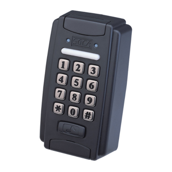
Page 3: Ⅰ . Special Features
ST320 Mode Setting Ⅰ. : SPECIAL FEATURES . 1 One set stand alone design. . 2 After installation of proximity reader and is connected to power , red power indicator on the front panel will light up. . 3 4 types of door opening modes: (1) Enter 4digit door opening password, identification code is 1. ... - Page 4 Status light ( Green ) Deny light (yellow flashing light) Press key light Alarm (yellow light on) Power light (Red) OK light(Green) Clear or escape key Confirmation key Door bell Types of proximity cards The following 3 types of cards are required to register before use. SC10 : Thin card , thickness 0.8 mm, ISO standard card ...
-
Page 5: Ⅲ. Installation Procedures
Ⅲ. INSTALLATION PROCEDURES Refer to appendix (Mounting of reader unit.) Users could install either 6pin or 5pin connector to see fit. Please refer to item 5 in installation guide on ~ Page 11 12 Ensure the power adapter's voltage and polarity are fitted correctly. ... -
Page 6: Ⅳ . Setting Mode And Functions
Ⅳ.SETTING MODES AND FUNCTIONS : * To enter into the system setting mode, first press #, then enter system password and press # subsequently to enter into system setting mode. When entered into system setting mode, the STATUS light (green ) on the panel will be on with a beep sound. Users should enter any functional selections within 20 seconds. ... -
Page 7: Deletion And Loss Of Card (Delete One Card)
2. Delete card : Deletion of user's card (such as loss of card), card number is the 6digit code indicated on the proximity card. * ENTER" # " STATUS LIGHT ON 1 BEEP PRES S SYSTEM WITH A BEEP SOUND SOUND ... -
Page 8: Door Lock Time Setting (Shunt Time)
4. Door lock time setting :Setting proximity reader relay ON time from 0199 seconds. All unlock time has to be filled in 2digit format such as enter 01 as 1 second. Setting 99 seconds as current state (for security system) and 00 second as single hit (for ... -
Page 9: Batch Registration (Add Series Cards)
6. Batch registration : Registering multiple cards and cards in series. Enter 6 digit card number, then enter amount of cards, in 4digit format (must be in full 4 digits, such as 100 pcs. , enter 0100). This system can also apply to single card entry. ... -
Page 10: Changing System Password (Command)
8. Change system password : To change system password, this reader's password is being preset at 4567. Please note that this password is necessary to enter into the system setting mode. * ENTER" #" STATUS LIGHT ON 1 BEEP PRESS SYSTEM ... -
Page 11: Deletion Of Batch Registration (Delete All Cards)
10. Delete all cards : Please note that this function will delete all registered card and cannot be retrieved. * EN TER" #" STATUS LIGHT ON 1 BEEP PRESS SYSTEM WITH A BEEP SOUND SOU ND 9 PASSWORD "#" 1 BEEP STATUS LIGHT ... -
Page 12: Ⅴ.installation Of Proximity Reader
Ⅴ.INSTALLATION OF PROXIMITY READER : 1. Reader connections : ST320 Wiring diagram Red AntiTamper switch,common contact Black AntiTamper switch,normally open contact Brown Reserved Orange AntiDamage alarm output 8PIN CONNECTOR Yellow AntiDuress alarm output Green Door detection sensor point 1 Blue Door detection sensor point 2 ... -
Page 13: Installation Of Electric Lock And Exit Push Button
BLU E 6 Pin AP10 GREEN DC 12V + BRO WN RED + ADAPTER AP10 D C 12V ADAPTER C. SOCA SL100 SL100 EXIT PUSH P BUTTON S + YELLOW AP10 PURPLE DC 12V BLUE 6 Pin GREEN ... -
Page 14: Installation Of Door Sensor, External Relay And Siren
3. Installation of door sensor, external relay and siren : A. Installation of reed switch (normal c lose), exteral rslay (antidamage) 6 Pin 8 Pin RE ED ( N.C) CO M N.C COM N. C N. O + + DC 12V EXTE RN AL REL AY ... -
Page 15: Ⅵ.precautions
(2) If door sensor detecting (such as reed switch) points are applied, please set ALARM to ON mode. For setting method, please refer to setting mode functional selection item 7 in the manual. 3. For installation, please link power supply wire and control wire through the base panel first and then fix the base panel onto the ... -
Page 16: Ⅶ.troubleshooting
Ⅶ.TROUBLESHOOTING 1. Card sensed but the door lock doesn't work. Solution: (1) Please check if the power supply is on the proximity reader and the electric lock. (2) If (1) is checked, please check the electric lock power supply and whether the connecting points are correct. (3) Continuous proximity. - Page 17 Appendix Mounting of reader unit: STEP1: Use screwdriver to dismantle or open the covers of screws at the top and bottom of the reader unit. STEP2: Use enclosed special L shape spanner to unscrew and remove the special acrews anticlockwise (direction).Please make ...
- Page 18 STEP4: Screw water proof pad with base cover tightly onto the wall. STEP5: Link connectors through water proof pad and base cover to connect to the reader unit. STEP6: Screw the front cover with base cover tightly with four screws(make sure all four Orings are ...
- Page 19 STEP4: Press the screws covers(top and bottom) firmly. Attention:(When mounting onto rough wall) Use appropriate size of flat acrylic or wood piece(Do not use metal piece) to mount onto rough wall with silicon glue.Screw or fit the base cover onto it. silicon glue ...
Need help?
Do you have a question about the ST-320 and is the answer not in the manual?
Questions and answers