Table of Contents
Advertisement
Quick Links
Advertisement
Chapters
Table of Contents

Subscribe to Our Youtube Channel
Summary of Contents for WiMo W2IHY
- Page 1 W2IHY 8 BAND AUDIO EQUALIZER NOISE GATE OPERATING MANUAL...
-
Page 2: Pin Mic Connector Pin
E-mail: Julius@W2IHY.COM 4 Pin Mic Connector Pin 1 Home Page: http:// www.w2ihy.com Power c 2000 W2IHY, ALL RIGHTS RESERVED + 7 to 14V dc DIN connectors shown on the side to be soldered DO NOT SOLDER TO SHIELD OF DIN... - Page 3 MIC OUT & POWER CABLE WIRING TABLE OF CONTENTS + Mic 8 Pin Mic Connector Pin 8 Introduction ......6 Japan Radio - Mic 8 Pin Mic Connector Pin 7 JST-135 JST-245 Yaesu 8 Pin Mic Connector Pin 6 FT990/ft992 Front Panel Controls ..
-
Page 4: Rear Panel Controls
MIC OUT WIRING OPTIONS TABLE OF CONTENTS Rear panel Controls ...12 5 PIN DIN MIC OUTPUT CONNECTION - Mic Output B + Mic Balanced MIC OUT A/B Output - Mic 5 Pin Male DIN - Phones Hi-Z Output Din connectors shown on side to be soldered - Power Bottom Panel Controls ... - Page 5 TABLE OF CONTENTS INTERNAL WIRING Preliminary Equalizer Settings.. . 20 Note that J1-X is the flat ribbon PC Boards and Parts cable shown on page 15 C41- .01uf - Mother Board ....21 PIN 1 PIN 7 J1-13 - 8 Band EQ Board .....22 PHONES MIC IN - Rear Connector Board ..23...
-
Page 6: Introduction
C40 - .01 mylar, tolerate R.F. C7, C13, C37, C39 - .1 uF ceramic monolithic The W2IHY 8 Band Audio Equalizer and Noise Gate solves two basic C39 - 4.7 uf tantalum electrolytic problems many hams experience. The Audio Equalizer allows the... -
Page 7: Front Panel Controls
8 BAND EQ BOARD FRONT PANEL CONTROLS PC BOARD LAYOUT AND PARTS C1 - 300pF mylar C15 - .1 uF mylar C2 - 390 pF mylar C16 - .1 uF monolithic C3 - 560 pF mylar C17 - .18 uF mylar This section describes each of the controls on the front panel. -
Page 8: Front Panel Controls
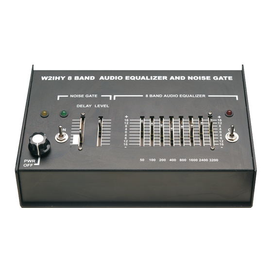
FRONT PANEL CONTROLS 8 BAND EQ MOTHER BOARD PC BOARD LAYOUT AND PARTS (4) Equalizer CONTROLS (R11-R18) These slide potentiometers work only when the Equalizer On/Off Switch S3 is in the on position. The potentiometers control the output of 8 bandpass filters. The center frequency of these filters are 50 Hz, 100 Hz, 200 Hz, 400 Hz, 800 Hz, 1600 Hz, 2400 Hz and 3200 HZ. - Page 9 FRONT PANEL CONTROLS (7) Noise gate Level (R19) This slide pot. works only when the noise gate is on. This pot. sets the level at which background noise will be not gated to the audio output. Pushing this control up will make the unit less sensitive to higher background ambient noise.
-
Page 10: Rear Panel Controls
REAR PANEL CONTROLS GETTING STARTED TUTORIAL Noise Gate Delay control sets the decay time of the trailing edge of the Mic Out Audio, when the noise gate turns off. This circuitry exponentially reduces the audio output when there is no audio present in the Mic In . -
Page 11: Rear Panel Controls
GETTING STARTED TUTORIAL REAR PANEL CONTROLS Before plugging the power transformer into the wall preset the following controls as indicated: Power, Equalizer Noise Gate switches all off. (12) MIC Input (J9) Mic Select to select microphone you will be using. Connect your microphone into the Mic In rear connector. -
Page 12: Mic Output B
CHANGING EQ BANDPASS REAR PANEL CONTROLS FILTER CENTER FREQUENCIES (17) Mic Output B (J4) Each EQ bandpass filter is very similar. The center frequencies, of each 5 Pin female DIN connector that has noise gate / equalizer bandpass filter is determined by the values of the capacitors and audio plus push to talk outputted. -
Page 13: Mic Output Level
BOTTOM PANEL CONTROLS J1-10 C12 - .018uf C10 - .01uf 23 21 (20) Mic Jumper Plugging the jumper (shorting block) puts +5V on the Mic In C20 - 100 uf C16 - .1 uf R1 line of the microphone's cartridge (11, 12 & 13). Required for mic's J1-7 such as ICOM’s Hm12, HM36 and Sm6 and the Heil Hmi and MH2 (made for the Elecraft radio’s) and other electret microphones.
Need help?
Do you have a question about the W2IHY and is the answer not in the manual?
Questions and answers