Sign In
Upload
Download
Table of Contents
Contents
Add to my manuals
Delete from my manuals
Share
URL of this page:
HTML Link:
Bookmark this page
Add
Manual will be automatically added to "My Manuals"
Print this page
×
Bookmark added
×
Added to my manuals
Manuals
Brands
Phenom Manuals
Microscope
ProX
User manual
Phenom ProX User Manual
Hide thumbs
1
2
Table Of Contents
3
4
5
6
7
8
9
10
11
12
13
14
15
16
17
18
19
20
21
22
23
24
25
26
27
28
29
30
31
32
33
34
35
36
37
38
39
40
41
42
43
44
45
46
47
48
49
50
51
52
53
54
55
56
57
58
59
60
page
of
60
Go
/
60
Contents
Table of Contents
Troubleshooting
Bookmarks
Table of Contents
Table of Contents
Things You Must Know
Introduction
Unpacking the Phenom Components
Packaging Contents
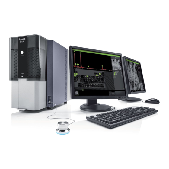
System Overview
Controls
Power Supply
Connections
Screens
Installing the Phenom
Preparation
Requirements for Positioning the Phenom Components
Assembling the Flat Panel Touch Screen Monitor
Connections
Connecting the Phenom
Activating the System
Switching on the Phenom
Switching 'On' the Flat Panel Touch Screen Monitor
Calibrating the Flat Panel Touch Screen Monitor
Using the Phenom
Preparation
Waking-Up the Phenom
Preparing Samples
Samples that Cannot be Prepared in Colloidal Graphite or Silver Paint
Particle Samples
Polymers
Metals
Biological Samples
Heavy Metal Coating
Loading Samples
Activating the Sample Holder
Operation
Using the Touch Screen
Optical Imaging
Adjusting Focus
Adjusting Brightness and Contrast
Adjusting Magnification (Prox / Pro)
Moving the Sample
Sample Overview
Storing Images
Electron Imaging
Adjusting Focus
Adjusting Brightness and Contrast
Magnifying the Image
Rotating the Image
Moving the Sample
Storing Images
Viewing Stored Images
Comparing Images (Prox / Pro)
Deleting Stored Images
Measuring on Stored Images (Prox / Pro)
Unloading the Sample
Switching off the Phenom Electron Source
Switching off the Phenom
Switching off the Flat Panel Touch Screen Monitor
Switching off the System Completely
Phenom Settings
Live Viewing Settings
Mode
Resolution
Quality
Intensity
Acquired Image Settings
Detector Mode
Presets
Quality
Resolution
Storing User Settings
Date and Time
Adjusting the Date
Adjusting the Time
Databar / Image Type / UI Mode
Databar
Image Type
UI Mode
Label
USB Stick / Mode
Mode
USB Stick
Advanced Settings
Shutdown
SW (Software) Version
Routine Pages
Source Tilt
Storesys(Tem)Info
Stigmate
Network
Connectivity
Maintenance
Troubleshooting
Error Recovery and Reporting
Rotary Knob State Indicator
Error Messages and Warnings
Power down
Rebooting the Phenom Software
Preparing the Phenom for Transport
Return Procedure
Prepare for Packing
Disconnecting and Packing
Technical Specifications
Advertisement
Quick Links
Download this manual
PW_Phenom_Pro_X_Pro_Pure_Print:PW_Phenom_G2_Pro_G2_Pure 19-11-13 20:54 Pagina 1
Phenom User Manual
ProX / Pro / Pure
Table of
Contents
Previous
Page
Next
Page
1
2
3
4
5
Advertisement
Table of Contents
Need help?
Do you have a question about the ProX and is the answer not in the manual?
Ask a question
Questions and answers
Related Manuals for Phenom ProX
Microscope Phenom Pure User Manual
(60 pages)
Microscope Phenom ProX Generation 5 User Manual
(62 pages)
This manual is also suitable for:
Pro
Pure
Table of Contents
Save PDF
Print
Rename the bookmark
Delete bookmark?
Delete from my manuals?
Login
Sign In
OR
Sign in with Facebook
Sign in with Google
Upload manual
Upload from disk
Upload from URL


Need help?
Do you have a question about the ProX and is the answer not in the manual?
Questions and answers