Advertisement
GS-X v.III Guarding Safety Controller
Packaging
1 ea. 47-142117-000 Pkg. Hold-to-Run Cable Assembly
*1 ea. 47-142118-000 Pkg. Hold-to-Run Switch
1 ea. 47-902601-000 Installation Instructions
* One per Center Item
Tools Required
- Straight (flat) Screw Driver
- Phillips (cross) Screw Driver
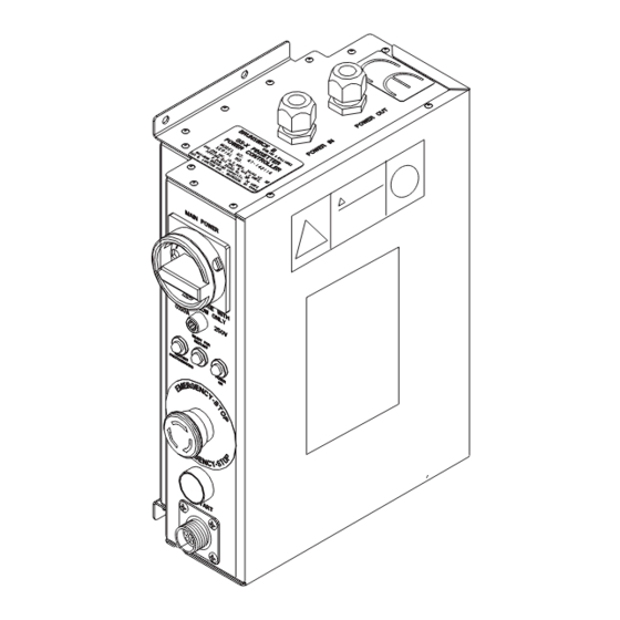
Hold-to-Run Cable Assembly 47-142117-000
The Hold-to-Run cable assembly provides a connection on the Safety Controller for the Hold-to-Run
switch. A cable must be wired into each safety controller where a Hold-to-Run operation is desired. Re-
fer to Figure 1.
September 2012
Hold-to-Run Switch
Figure 1
© Brunswick Bowling & Billiards Corp. 2012. All rights reserved.
1
47-902601-000
Advertisement
Table of Contents

Related Manuals for Brunswick GS Series

Summary of Contents for Brunswick GS Series
- Page 1 1 ea. 47-142117-000 Pkg. Hold-to-Run Cable Assembly *1 ea. 47-142118-000 Pkg. Hold-to-Run Switch 1 ea. 47-902601-000 Installation Instructions * One per Center Item Tools Required - Straight (flat) Screw Driver - Phillips (cross) Screw Driver Hold-to-Run Cable Assembly 47-142117-000 The Hold-to-Run cable assembly provides a connection on the Safety Controller for the Hold-to-Run switch. A cable must be wired into each safety controller where a Hold-to-Run operation is desired. Re- fer to Figure 1. Figure 1 © Brunswick Bowling & Billiards Corp. 2012. All rights reserved. September 2012 47-902601-000...
- Page 2 Hold-to-Run Cable Installation in the Safety Controller WARNING! Turn off the main power to the pinsetter at the main electrical panel and turn “OFF” the main power switch on the safety controller. 1. Remove and discard cover plate from safety controller and retain all screws for re-use. Refer to Figure 2. Figure 2 IMPORTANT!: Save all screws. 2. Remove the cover from the safety controller.
- Page 3 3. Install hold-to-run cable assembly into safety controller with the 4 screws from step 1. Refer to Figure 3. Figure 3...
- Page 4 4. Wire the hold-to-run cable assembly to safety controller. Refer to Figure 4 and Schematic of Hold-to-Run Cable Figure 1. Figure 4 5. Secure the cover removed in step 4 to the safety controller.
- Page 5 Hold-to-Run Switch 47-142118-000 The Hold-to-Run switch is a manually operated switch that allows work to be conducted in the GS-X pinsetter areas while the machine is operating. Refer to Figures 5 & 6. Figure 5 Figure 6 NOTE: When the Hold-to-Run switch is not in use, remove it from the safety controller and store in a secure location.
- Page 6 The Hold-to-Run switch has three positions that provide three operating modes. Refer to Figure 7. Figure 7...
- Page 7 Functional Test of the Hold-to-Run Switch WARNING! The effectiveness of the Hold-to-Run switch must be tested before use. Occupy a safe area, outside of the GS-X pinsetter and away from any dangerous parts or areas that could cause injury. 1. With the hold-to-run switch connected to the safety controller (refer to page 4, Figure 6) in posi- tion 1 state (off, push button not pressed, GS-X pinsetter not operating), check all the protective devices, interlocks and sensors before any work or the dangerous state of the pinsetter is initiated.
Need help?
Do you have a question about the GS Series and is the answer not in the manual?
Questions and answers