Advertisement
Table of Contents
Advertisement
Table of Contents

Subscribe to Our Youtube Channel
Summary of Contents for Royal Enfield Z-Drive 130
- Page 1 ENFIELD Z-DRIVE TRANSOM UNITS SERVICE MANUAL AND PARTS LIST LEICESTER ENGLAND...
- Page 2 ENFIELD Z-DRIVE TRANSOM UNITS SERVICE MANUAL PARTS LIST MODELS 130, 130H, 130NON SWIVEL BOB KNOWLES PLANT SERVICES LTD. MARINE DIVISION 9 VULCAN ROAD LEICESTER LE5 5EF TEL: 0116 253 8685 FAX: 0116 251 4977 ISSUE TWO APRIL 1980 PUBLICATION NUMBER 7768...
-
Page 3: Table Of Contents
CONTENTS Page DESCRIPTION ..........4 DATA ........... 5 OPERATING, LUBRICATION AND MAINTENANCE INSTRUCTIONS .. -
Page 4: Description
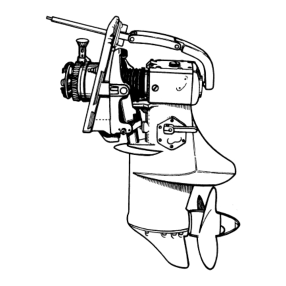
DESCRIPTION The ENFIELD "Z-DRIVE" transom unit is a transom engines can be used providing manufacturers are mounted drive unit incorporating a reverse and informed when ordering. reduction gear. It is suitable for adaption to either petrol or diesel engines within its power capacity. GEAR CHANGE Installation is easily accomplished, the standard An external lever, on the port side of the unit,... -
Page 5: Data
TECHNICAL DATA The unit serial number, consisting of 6 digits number should be quoted on all spares and service commencing with 2ZE, is found stamped on the port queries. The Power Trim Model carries its own serial side of the Drive Housing. This number and the suffix "H". -
Page 6: Operating, Lubrication And Maintenance Instructions
OPERATING, LUBRICATION AND MAINTENANCE INSTRUCTIONS The Z-DRIVES are a transmission system for boats (218) just forward of the propeller. These should be allowing a direct coupling to an engine without a inspected and replaced as they become eaten away. gearbox being required. Also incorporated are steering A craft must be fitted with sufficient anodes to and either a kick-up system or power trim. -
Page 7: Installation Details
INSTALLATION DETAILS INSTALLATION OF DRIVE UNIT REMOTE CONTROL The assembly is bolted through the transom Remote control of both engine throttle and gear which should be prepared as shown in Figs. 1, change is by means of a "single lever" control 2,3,4,5.. -
Page 8: Installation Instructions
INSTALLATION INSTRUCTIONS When assembling the "Z-DRIVE" transom unit to POWER TRIM MODEL 130H the craft for the first time, it may be an advantage to Loosen the clip around the gaiter over the use the "Z-DRIVE" transom plate for marking off universal joints (transom plate end only. -
Page 10: Installation Hydraulic Lift Kit
INSTALLATION HYDRAULIC LIFT KIT 130 NON SWIVEL Z-DRIVE If the Hydraulic Hand Lift is to be used. Cylinder. Smear Cylinder liberally with water Before placing Cylinder into Recess Housing proof grease and position into Recess in draw Piston from Cylinder close valve on Transom Plate. -
Page 11: Overhaul Section
OVERHAUL SECTION TRANSOM PLATE ASSEMBLY 130 1. Transom Plate Assembly - 130 To Disassemble the Transom Plate Assembly 2. Transom Plate Assembly - 130H. 130 Non Swivel. If the transom plate assembly has been removed from 3. Swivel Fork the craft with the close coupling components still 4. - Page 12 The ball bearing (21) is retained by circlip (23) which To re-fit the swivel plate assembly to the transom should be removed before the bearing (21) is plate, the plate has to be slid over the spigot on the withdrawn. swivel hub and at the same time the lug at the bottom The new bearings are pressed home hard against their of the swivel plate engaged within the hook of the...
- Page 13 The ball bearing is retained by circlip which To re-fit the swivel plate assembly to the transom (21) (23) should be removed before the bearing plate, the plate has to be slid over the spigot on the (21) withdrawn. swivel hub and at the same time the lug at the bottom The new bearings are pressed home hard against their of the swivel plate engaged within the hook of the locating shoulders with the bearings (22 &...
-
Page 14: Plate A.
Lift the propeller .shaft (204) complete with bearings, This will enable the main body of the "ZDRIVE" to be bevel gears, thrust washers, seal and dog clutch from lifted clear of the hydraulic cylinders. Now, from inside the housing. the hull, unscrew the two tubing nuts (94) which hold Withdraw the seal circlip (217) and seal (213) the oil supply and return pipes to each cylinder, arid complete with housing (214) from the rear end of the... - Page 15 The vertical drive shaft (194) can now be removed, fitment of the gear change shaft bearing (126) and (126A) as this care being taken to prevent the removable collar (198) varies with left or right hand rotation units. from falling and becoming lodged in the housing. Assemble the thrust washer (134), circlip (85) and With a suitable extractor remove the roller bearing woodruff key (132) to the gear change shaft.
- Page 16 machined flat. On these units when re-fitting the Thoroughly clean and inspect all components for skeg a suitable jointing compound should be used. wear, pitting and cracks, etc. Renew worn or Place the skeg (162) in position on the housing, defective parts.
- Page 17 7. CHECKING FOR BACKLASH Re-fit into bearings in bearing housing top bevel gear shimming is done by using extra joints (178) (220). Slip gear (221) into bearings at the top of the On ahead and astern gears (238) on propeller housing.
-
Page 18: Parts List
PARTS LIST METHOD OF IDENTIFYING AND Plate Assembly on Page 18 is read as: ORDERING SPARE PARTS 33432309 Sleeve, Swivel Plate The Parts List contains the numbers and descriptions Locking Plunger of all parts comprising the Model 130, 130H, 130 Non This is indicated 'S' and, therefore, is Swivel Transom Units, together with a Supplementary available as a spare part. - Page 19 Ref. Qty. Part Description Remarks Req. Model TRANSOM & SWIVEL PLATE ASSEMBLIES 130 only 37814125 Assembly, transom plate comprising:- 37537182 Transom Plate 32815117 Pin, Nylon 32114126 Plug Breather 7055 Nipple, Greasing 36131314 Block, zinc 2224568 Screw, zinc block to transom plate 33432309 Sleeve, swivel plate locking plunger 2725499...
- Page 21 Ref. Qty. Part °r Description Remarks Req. N°, Model TRANSOM & SWIVEL PLATE ASSEMBLIES 130/130H 37466511 Shaft input (contd) 2584601 C.V.. Joint - input 33531116 Nut. C.V. Joint to input shaft 33121412 Washer. C.V. Joint to input shaft Non swivel 2581215 Coupling, flexible 0096635...
- Page 22 Plate B Model 130H Assy.
- Page 23 Ref. Qty. Part °r Description Remarks Req. N°, Modet HYDRAULIC TRIM/TILT (eontd) 7167 Terminal 7161 Connector - bullet 7291 Terminal - bullet STEERING LINKAGE 7242 Assembly steering arm and tee link 130/ 7225 Assembly link and bushes comprising:- 130H 7067 Link steering, upper 2513906 Bush steering, upper link...
- Page 24 Ref. Qty. Part Description Remarks Req. Model ASSEMBLY BODY, SKEG & GEARS, etc. 130/ 710954 Assembly body and bearings, comprising:- 130H 0999999 Assembly body comprising:- 37522491 Body, drive 37171751 Skeg 2222256 Socket screw, skeg to body Stainless steel 33111411 Washer, plain Stainless steel 2513911 Bush, centre pin swivel fork...
- Page 25 Ref. Qty. Part °r Description Remarks Req. Model ASSEMBLY BODY, SKEG & GEARS, etc. (contd..) 130/ 33884112 Gaiter - C.V. Joint cover 130H 7002 Clip, sealing gaiter GEARS AND SHAFTS - BODY 130/ 31174141 Bevel gear top (1 in body and 1 in rear 130H bearing housing) 31174132...
- Page 28 Ref. Qty. Part Description Remarks Model 7114 Instruction - Transfer (top link) 7125 Motif - Port (Body) 7126 Motif - Starboard (Body) 130H 7114 Instruction - Transfer (Top link) 7115 Motif - Port (Body) 7116 Motif -Starboard (Body) "Z-DRIVE" TRANSOM UNIT ACCESSORIES AND SERVICE PARTS Attachment of "Z-DRIVE"...
- Page 29 Ref. No. Part Number Description Model 7112 Spinner Nut 130/130H 33177511 Tabwasher 130/130H 33144114 Distance Piece 130/130H Reference 261 Part Number Part Number Left Hand Description Right Hand Rotation Rotation 8005 Propeller Assembly - 11'/," (292mm) dia. X 11" (279mm) pitch X 3 blade 8004 8003 11'/x"...
Need help?
Do you have a question about the Z-Drive 130 and is the answer not in the manual?
Questions and answers
Hello what is the propeller made of? Thanks