Table of Contents
Advertisement
Quick Links
Advertisement
Table of Contents

Summary of Contents for Metal Samples Company MS4500E
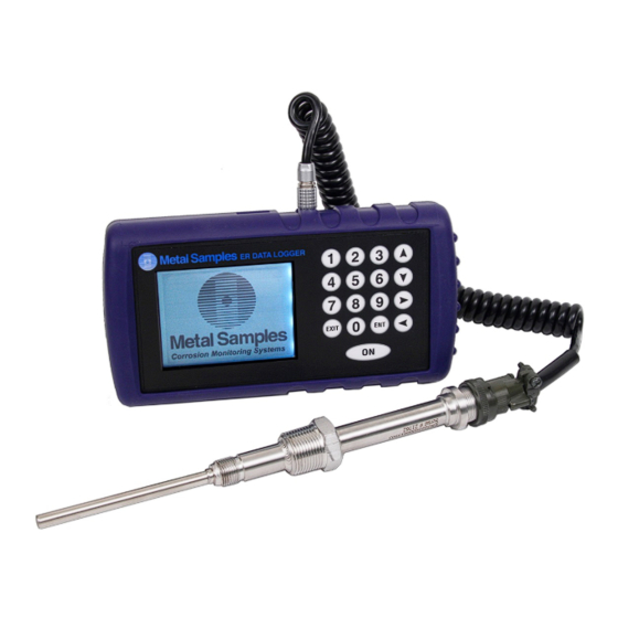
- Page 1 Metal Samples Company A Division of Alabama Specialty Products, Inc. 152 Metal Samples Rd., Munford, AL 36268 Phone: (256) 358-4202 Fax: (256) 358-4515 E-mail: msc@alspi.com Internet: www.metalsamples.com...
-
Page 2: Table Of Contents
i. New Probe .................... 9 ii. Existing Probe .................... 9 iii. Delete Existing Probe .................. 10 b. Make Measurement .................. 11 c. Recall Readings .................... 12 d. Delete Readings .................... 13 e. Set Time & Date .................... 14 f. Set Measurement Timer .................. 15 g. Communications ..................... 16 h. Language ...................... 22 i. Power Off ...................... 22 j. Backlight On/Off .................... 22 C. Maintenance .......................... 23 1. Testing the MS4500E High Resolution Data Logger with the Meter Prover .... 23 D. Troubleshooting ........................ 24 III. Service and Warranty Information ....................... 25 A. Warranty .......................... 25 B. Obtaining Service and Returning the Instrument for Repair ........... 25 C. Instrument Repair Form ...................... 26 Appendix A ‐ Drawings .......................... 27 Control Drawing (Hazardous Area Wiring Diagram) .............. 28 Appendix B – Revision History ........................ 29 ... -
Page 3: Introduction
After taking a reading, the instrument displays metal loss in mils and corrosion rate in mils per year (mpy). The reading can then be stored to memory or discarded. All stored readings are automatically time and date stamped. Readings are stored to non‐volatile Flash memory which retains data without the need for a battery backup. The MS4500E High Resolution ER Data Logger can store 16,000 readings per probe on up to 250 different probes (4 million total). Stored data can be downloaded directly to a USB Flash (“jump”) drive in non‐ hazardous areas. Data can be opened and charted using the provided CDMS software, or can be imported into any standard data analysis (spreadsheet) program such as Microsoft Excel. Data can also be reviewed and charted on the instrument’s LCD display for quick reference. B. Principles of Operation The MS4500E High Resolution ER Data Logger operates on the Electrical Resistance (ER) technique and is used in conjunction with an ER probe. The ER probe utilizes a resistive sensing element manufactured from the material of interest (or a close approximation) which is exposed to a corroding environment. This is called the Exposed or Corroding Element. The resistance of the Exposed Element is directly related to its thickness, so as the element corrodes the resulting loss of metal causes a proportional increase in the element’s resistance. The probe also contains an internal Reference Element which is used to compensate for the influences of temperature on the Exposed Element. The MS4500E High Resolution ER Data Logger is designed to work with any standard ER probe, but it is recommended that Cylindrical and Large Flush type probes be used to ensure optimum performance. Their physical design places the Reference Element in closer proximity to the Exposed Element compared to other probe types, providing more effective temperature compensation and thus reducing the effects of thermal noise. 1 ... - Page 4 10 5 Flush (Large) Preferred 20 10 40 20 Table 1. Standard ER Probe Elements The MS4500E High Resolution ER Data Logger measures an ER probe utilizing a high‐resolution, 16‐bit measurement. This allows the unit to detect much smaller amounts of metal loss, thus responding faster to corrosion events and upsets. At 16‐bit resolution the MS4500E ER Data Logger can measure metal loss amounts as small as 0.004% of the probe life. For highly sensitive probes such as the 5‐mil large flush shown above, that results in a detection limit of less than one angstrom. 2 ...
-
Page 5: Technical Specifications
C. Technical Specifications Model MS4500E High Resolution ER Data Logger Physical Data Instrument Weight (w/ boot): 1.71 lb. (0.78 kg) Total Weight w/ Case & Accessories: 6.96 lb. (3.16 kg) Instrument Dimensions (w/ boot): 8.75"L x 4.54"W x 2.20"D (21.77cm x 11.53cm x 5.59cm) Instrument Dimensions (w/o boot): 7.50"L x 4.00"W x 2.00"D (19.05cm x 10.16cm x 5.08cm) Carrying Case Dimensions: 14.50"L x 11.38"W x 5.88"D (36.83cm x 28.89cm x 14.92cm) Operating Temperature: ‐4° to 130°F (‐20° to 54°C) Storage Temperature: ‐4° to 158°F (‐20° to 70°C) Operating Humidity Range: 30% ‐ 95% Performance Data Measurement Type: ER measurement using any standard ER Probe Types Preferred Probe Types: Cylindrical, Flush(Large) Compatible probe types: Tube Loop, Wire Loop, Flush (Small) Range: 0 ‐ 25,000 probe life units (displayed as 0.00 to 1000.00 PLU’s in 0.04 increments) Resolution: 0.004% of Probe Life Repeatability: ± 0.1% of Full Scale Cycle Time: 25 Seconds Electrical Data ... -
Page 6: Start Up And Operation
II. Start‐up and Operation A. Receiving the MS4500E High Resolution ER Data Logger Check the MS4500E High Resolution Data Logger for any shipping damage when it is first received. When the unit is unpacked, verify that the following items are included: Carrying Case Data Logger Meter Prover User’s Manual Probe Cable In the event of shipping damage, quantity shortage, or missing items, it is recommended that the event is documented immediately and that digital photographs are taken. Any shortages or missing items should be reported to Metal Samples immediately. In the event of shipping damage, a claim should be opened with the responsible carrier. B. Start‐Up Using this product in any way other than that specified within this manual may impair the CAUTION: intrinsic safety protection. l'utilisation de ce produit de toute autre manière que celle spécifiée dans le présent manuel ATTENTION : peut altérer la protection de sécurité intrinsèque. Start‐up of the MS4500E High Resolution Data Logger involves the following steps: 1. Port Details and Probe Connection ... - Page 7 The MS4500E High Resolution Data Logger is supplied with a probe cable and it can be connected to the probe whose metal loss value needs to be measured, no additional hardware is necessary. Connect the probe cable ‘Lemo’ connector end to the data logger probe connector ‘J9’ available on top of the data logger. Connect the other end of the probe cable i.e. probe connector (MS Connector) to the probe. 2. Power‐Up The unit is supplied with 4 AA batteries installed. The instrument can be powered up by pressing the ‘ON’ button on the Keypad . The Start‐up screen with the Metal Samples logo will appear on the screen; the start‐up screen confirms the software version currently running and the SD card status. SELECT PROBE MAKE MEASUREMENT RECALL READINGS DELETE READINGS SET TIME & DATE SET MEASUREMENT TIMER COMMUNICATIONS LANGUAGE / IDIOMA / LINGUAGEM POWER OFF 10. BACKLIGHT ON/OFF Version 1.7...
-
Page 8: Safe Area Usage
The MS4500E High Resolution Data Logger is approved for use in hazardous areas, but can be used in non‐hazardous areas as well. The data transfer from the unit to PC should be done in a safe area. A certified USB isolator should be used between the unit and PC for data transfer. b. Hazardous Area Usage This section provides general guidelines for hazardous area usage. However, CAUTION: regardless of anything stated here, the MS4500E High Resolution Data Logger must be used in full compliance with the control drawing located in Appendix A and all of the local area requirements. The entity parameters of the unit are given below. Cette section fount des directives générales pour l’utilisation en zone dangereuse ATTENTION : Toutefois, et indépendamment de toute déclaration faite ici, L’enregistreur de données de haute résolution MS4500E doit être utilise en pleine conformité avec le schéma de contrôle donne en page 20 et avec toutes les exigences du locale zone dangereuse. J9-USB Port & J11- ER Probe cable Connector = 4.94V = 1.39A = 1.28 W = 21.6 uF (Shared between all Connectors) -
Page 9: Battery Replacement
c. Battery Replacement The battery compartment is located on the back of the instrument. You must first remove it to access the battery compartment. To replace the batteries, first loosen and remove the cover screw, then remove the battery cover to expose the batteries. Remove the old batteries and replace them with four new 1.5V ‘AA’ size batteries, being sure to follow the polarity (+/‐) symbols in the battery compartment. Replace the battery cover and cover screw. WARNING: Do not mix old and new batteries. Do not mix batteries of different types (such as alkaline and lithium.) Duracell PC1500 battery is required for intrinsic safety. The cover screw is used to prevent unauthorized tampering of the batteries and is required to ensure intrinsic safety. Do not over‐tighten the cover screw, as this may damage the instrument case. ATTENTION: Avertissement ! Ne mélangez pas des piles neuves et usées. Avertissement ! Ne mélangez pas des piles de types différents (telles que des piles alcalines etdes piles lithium.) ... -
Page 10: Setup And Operation
3. Setup and Operation MAIN MENU The MS4500E allows you to measure metal loss and corrosion rate. Review this section which describes the functions that display on the Main Menu: SELECT PROBE MAKE MEASUREMENT RECALL READINGS DELETE READINGS SET TIME & DATE SET MEASUREMENT TIMER COMMUNICATIONS LANGUAGE / IDIOMA / LINGUAGEM POWER OFF 10. - Page 11 ENTER NEW PROBE ‐ To enter the ID of a new probe, select ‘ENTER NEW PROBE’; the next screen allows you to enter the ID number and the type. 1. Enter the Probe ID using the number keys. (Use the Up/Down arrows to scroll between alphanumeric characters. Use the Right/Left arrows to advance to the next character or go back to the previous character.) When a 4‐digit Probe ID is entered the cursor automatically advances to the Probe Type field. 2. Use the Up/Down arrows to select the Probe Type. Use the Right arrow to advance to the Probe Life field. 3. Enter the Probe Life using the number keys. 4. Press ENTER. PROBE ID: 5385 PROBE TYPE: WIRE 40 PROBE LIFE: 10.0 PRESS UP / DOWN ARROW TO CHANGE ...
- Page 12 DELETE EXISTING PROBE It is occasionally necessary to remove the ID of a probe from memory, for example: o When the memory bank is full o When a probe is no longer used To delete the ID of a probe in memory, select DELETE EXISTING PROBE. DELETE PROBE PROBE ID: 1000 USE UP / DOWN ARROW TO CHANGE PRESS ENTER TO DELETE 1. Enter the probe ID ‐ use the number keys (press the DOWN arrow if you make an error). 2.
-
Page 13: B. Make Measurement
b. Make Measurement Select a probe before you run the function In order for you to run ‘MAKE MEASUREMENT’ ‘RECALL READINGS’ & ‘DELETE READINGS’, you must have already selected a probe from memory. See ‘SELECT PROBE’ from the Main menus (page 8). To take measurement from probes in memory, select ‘ ’ menu from MAKE MEASUREMENT the Main Menu: SELECT PROBE MAKE MEASUREMENT RECALL READINGS DELETE READINGS SET TIME & DATE SET MEASUREMENT TIMER COMMUNICATIONS LANGUAGE / IDIOMA / LINGUAGEM ... -
Page 14: C. Recall Readings
Recall Readings Select ‘ ’ to look at data from different dates. RECALL READINGS ENTER NEW PROBE DELETE EXISTING PROBE 1000: WIRE LOOP PL:10.0 2500: CYLINDRICAL PL:10.0 2500: CYLINDRICAL PL:10.0 0434: TUBE LOOP PL:10.0 PRESS ENTER TO SELECT ... -
Page 15: D. Delete Readings
Delete Readings Select ‘ ’ from Main Menu to erase a reading from memory. DELETE READINGS Periodically delete readings to create more free storage area in memory. ENTER NEW PROBE DELETE EXISTING PROBE 1000: WIRE LOOP PL:10.0 2500: CYLINDRICAL PL:10.0 2500: CYLINDRICAL PL:10.0 0434: TUBE LOOP PL:10.0 PRESS ENTER TO SELECT ... -
Page 16: Set Time & Date
Set Time & Date Select ‘ ’ from Main Menu to set the internal clock of the MS4500E SET TIME & DATE Data Logger. In order for information in memory to be useful and accurate, be sure the time and date are accurate. The Time and Date are set at the factory, but may need to be adjusted to your CAUTION: time zone. Also, if you try to change the Date or Time and it conflicts with stored information, the MS4500E will display N/A. l'heure et la date sont définies à l'usine, mais ils peuvent être ajustées à votre ATTENTION : fuseau horaire. Aussi, si vous essayez de changer la date ou l'heure et que ce ci conflit avec l'information mémorisée, le MS4500E affichera N/A. DATE (MM / DD / YY): 04 / 27 / 15 ... -
Page 17: Set Measurement Timer
Set Measurement Timer Select ‘ ’ from Main Menu to set automatic probe SET MEASUREMENT TIMER reading at set intervals. The MS4500E Data Logger periodically wakes up and takes the measurement and stores the reading. Select a probe before you run the function In order for you to run MAKE MEASUREMENT, you must have already selected a probe from memory. See Select Probe ID from the Main menus (see page 8). ENTER NEW PROBE DELETE EXISTING PROBE 1000: WIRE LOOP PL:10.0 2500: CYLINDRICAL PL:10.0 2500: CYLINDRICAL PL:10.0 0434: TUBE LOOP PL:10.0 ... -
Page 18: Communications
Communications The MS4500E Data Logger has the ability to store readings as they are taken. These readings can later be transferred to your PC via USB port. To transfer data to a PC it is necessary to install the Corrosion Data Management Software (included). To download data from an instrument: • Connect the instrument to an available PC USB port . • Turn the MS4500E on. • Run the Corrosion Data Management Software • Open the Instrument Download Center • Select the serial port and instrument • Click the Download button (ensure that Part Status toggles to “On”). • Select ‘ ’ menu from the Main Menu of the instrument. COMMUNICATIONS • Select ’ ’ or Select the Probe data you wish to download. TRANSFER ALL TRANSFER ALL 1001: WIRE LOOP ... - Page 19 If data does not appear in the data window at all, verify that: The instrument is connected to a valid serial or USB port All cables are securely connected The message “Port Status: On” appears in the status bar There are no errors on the instrument If using a USB adapter, ensure that the device drivers have been i nstalled. Selecting a Serial Port When the MS4500E is connected to the USB port it will appear as a virtual COM port. Use the Serial Port selection box to select the virtual COM port number. If the COM port number is unknown, it can be found in Windows Device Manager under “Ports (COM & LPT)”. Selecting an Instrument Use the Instrument option box to select the model of Metal Samples instrument being downloaded. This sets the appropriate communication parameters, which will be displayed in the status bar at the bottom of the window (“9600,N,8,1” for an MS1500, “2400,N,8,1” for an MS3500). Downloading Data To toggle the selected port on and off, click the Download button. Toggling the port on and off will also clear the data window. Once a valid serial port and instrument have been selected, click the Download button to turn the port on and enable the computer to receive data. If a valid serial port has been selected, the status bar at the bottom of the window will display the message “Port Status: On”. If an invalid serial port has been selected, an error message will appear, and the status bar will display the message “Port Status: Off”. If this happens, another serial port should be selected. Saving Data To save the data in the data window, click the Save button. The data is comma‐delimited A SCII text. ...
- Page 20 Data Analysis The D ata A nalysis u tility i s a convenient t ool f or c harting d ata f rom Metal Samples ER and LPR data logger instruments. The Data A nalysis utility can be opened from the Main Menu, or it can be opened directly from the Instrument Download Center. If the Data A nalysis utility is opened from the Instrument Download Center, the contents of the data window will be loaded into the chart. However, if the Data A nalysis utility is opened directly from the Main Menu, a valid data file must be loaded. The Select File box will open to allow selection of a data file. Loading a Data File After selecting a data file (or clicking the Chart Data button from the Instrument Download Center) a status window will display the progress of the file being opened, along with the Instrument Type, ...
- Page 21 Printing Data The data table can be printed by clicking Print in the Options menu. A print dialog box will be displayed to allow printer selection and setup. Creating A C hart To chart the selected data, click the Chart Data button, or select Chart Data from the Options menu. The chart will be displayed in a new w indow. Printing a C hart A chart can be printed using the Print Chart option in the File menu. A print dialog box will be displayed to allow printer selection and setup. Exporting a Chart A chart can be exported to other applications using the Copy Chart option in the File menu. This will copy both the chart and the raw data to the Windows ® Clipboard. The chart can then be inserted into other applications using the Paste function. Note: In some applications, using the Paste function will insert the raw data instead of the chart. In this case, use the Paste Special function, then select Picture to insert the chart. ...
- Page 22 • Finding A Data Points Value While viewing the chart, the value of any data point can be determined by s imply c licking i t. The v alue will be d isplayed in t he charts tool‐tip box (a small text box that is displayed near the mouse pointer). If the tool‐tip box does not appear immediately after clicking the data point, hold the mouse pointer stationary over the chart background for a moment. The Tools Menu The Tools m enu contains a c ollection o f u tilities f or v iewing and manipulating the chart. The Tools menu can be accessed by clicking ...
- Page 23 Zoom I n Zoom In allows a region of the chart to be enlarged so that it may be viewed in greater detail. To enlarge a region of the chart, click on the two data points that define the left and right boundaries of the region. In zoom mode, the mouse pointer will change to a cross‐ hair. When zoom mode ends, the mouse pointer will return to its normal state. To cancel zoom mode, click Cancel Zoom In from the Tools menu, or simply press the Esc key. Zoom O ut Zoom Out restores the initial view of the chart, which displays the full data set. Calculate Corrosion Rate If the chart contains ER data, the Calculate Corrosion Rate option will become available under the Tools menu. This option allows the corrosion rate to be calculated between any two data points on the chart. To calculate the corrosion rate click Calculate Corrosion Rate, then click two data points. The corrosion rate between those two data points will be displayed. In calculate mode, the mouse pointer will change to an arrow/question mark. When calculate mode ends, the mouse pointer will return to its normal state. To cancel a calculation, click Cancel Calculate from the Tools menu, or simply press the Esc key. 21 ...
-
Page 24: Language
Language / Idioma / Linguagem Select ‘ ’ from Main Menu to select the LANGUAGE / IDIOMA / LINGUAGEM language. ENGLISH ESPANOL PORTUGUES FRANCAISE PRESS ENTER TO SELECT PRESIONAR ENTPARA SELECCIONAR PRESSIONAR ENT PARA AJUSTAR TAPER ENTRER POUR REGLER ... -
Page 25: Maintenance
C. Maintenance Once installed, the MS4500E High Resolution ER Data Logger requires no maintenance. However, it is important to verify the following items periodically to ensure continued safe operation. Before performing any tests or maintenance on the MS4500E High Resolution ER Data CAUTION: Logger, ensure that all hazardous area requirements are met. : Avant d’effectuer tout essai ou entretien de l’enregistreur de données de haute ATTENTION résolution MS4500E, il faut d’abord s’assurer que toutes les exigences de zone dangereuse soient remplies. Inspection Item Frequency Inspect the rubber boot for any signs of damage. Replace as necessary. Annually Inspect the probe cable / connector for any signs of damage. Replace as necessary. Annually Replace the Batteries As needed ... -
Page 26: Troubleshooting
1. Ensure that the probe is operational and is not completely corroded. This can be done in two ways. a. Test the probe with another portable ER meter if available. b. Test the probe with a portable resistance or continuity meter as follows: i. Connect one test lead to pin ‘A’ of the probe’s 6‐pin connector. ii. Measure continuity to each of the other pins. There should be continuity (low resistance) to each pin. NOTE: Continuity on each pin does not ensure that the probe is good. However, if you find an open circuit on any pins then it is almost certain that the probe is bad and should be replaced. 2. Ensure the battery voltage. 3. Test the MS4500E High Resolution ER Data Logger transmitter using the supplied Meter Prover (see page 23.) These basic checks should indicate the source of any problem (probe, power supply, wiring, etc.). If it is determined that the MS4500E High Resolution ER Data Logger is malfunctioning, or if you need further assistance in troubleshooting, contact Metal Samples Technical Support. If the MS4500E High Resolution ER Data Logger transmitter shows any signs of damage, remove CAUTION: it from service immediately and consult the factory. Si l’Émetteur de l’Enregistreur de données de haute résolution présente des signes de ... -
Page 27: Service And Warranty Information
III. Service and Warranty Information A. Warranty Metal Samples warrants that any part of the model MS4500E High Resolution ER Data Logger and accessories which proves to be defective in material or workmanship within one year of the date of original shipment to Purchaser will be repaired or replaced, at Metal Samples option, free of charge. This warranty does not cover (1) probe assemblies, (2) items expendable in nature, or (3) items subject to damage from normal wear, misuse or abuse, or failure to follow use and care instructions. All damaged items are to be shipped at Purchaser’s expense to and from Metal Samples which shall have the right to final determination as to the existence and cause of a defect. The foregoing shall constitute the sole and exclusive remedy of any purchaser of Metal Samples products for breach of warranty and IS EXCLUSIVE AND IN LIEU OF ALL OTHER WARRANTIES, EXPRESSED, IMPLIED OR STATUTORY, INCLUDING THE IMPLIED WARRANTIES OR MERCHANTABILITY AND FITNESS. IN NO EVENT SHALL METAL SAMPLES BE LIABLE FOR SPECIAL OR CONSEQUENTIAL DAMAGES, OR FOR ANY DELAY IN THE PERFORMANCE OF THIS WARRANTY DUE TO CAUSES BEYOND ITS CONTROL. The technical information and suggestions contained herein are believed to be reliable, but they are not to be construed as warranties since conditions of use are beyond our control. B. Obtaining Service and Returning the Instrument for Repair If you experience problems with your instrument please contact the factory at 256‐358‐4202 and ask for customer support for instrumentation. Our customer support department will assist you in troubleshooting your instrument. ... -
Page 28: Instrument Repair Form
C. Instrument Repair Form This form may be photocopied for use when returning an instrument to Metal Samples for repair. Please fill in all known information and enclose a copy of the completed form with the instrument. General Information Model Serial Number Number Date of RMA Number Purchase* *If known. Contact Information for Repair Contact Name Company Phone E‐mail Number Address Return Shipping Information Recipient Name* Company* ... -
Page 29: Appendix A: Drawings
Appendix A: Drawings Control Drawing (Hazardous Area Wiring Diagram) ... - Page 30 USB Port For data transfer to 1, 2 USB Flash Drive Only PROBE USB-A Mini USB-B port for data transfer to PC Model MS4500E ER Data Logger EXIT 02/18/15 Control Drawing MS4500E Hand Held Data Logger EXWDB-000085...
-
Page 31: Appendix B: Revision History
Appendix B: Revision History Revision Date Changes 0 8/15/2014 Initial Release Mini USB entity parameters changed A 5/22/2015 B 6/01/2015 Mini USB entity parameters changed C 7/19/2015 Marking information added for America D 8/04/2015 Warning statements added in French & Temperature ratings E 10/06/2016 Backlight On/Off added to main menu ...
Need help?
Do you have a question about the MS4500E and is the answer not in the manual?
Questions and answers