Advertisement
Quick Links
Micro Switch G2
Micro Smart Energy Switch G2
(Generation 2)
(In-Wall Z-Wave Appliance Module w/ Energy Monitor)
Introduction:
The Aeotec Micro Smart Energy Switch G2 is a
low-cost Z-Wave appliance module specifically used
to enable Z-Wave command and control (on/
off) for existing in-wall switches. It can also report
immediate wattage consumption or kWh energy
usage over a period of time.
The wireless module is powered from the mains
supply and is a three-wire design which requires
a neutral connection. In the event of power
failure,
non-volatile
memory
retains
programmed information relating to the units
operating status.
It also is a repeater in the Z-Wave network.
Acting as a bridge for communication, it will
forward Z-Wave command messages to their
destinations if the originating controller is out of
range from the destination node.
By taking advantage of the Z-Wave mesh
network, commands can be routed to their
destination via intermediary "listening" Z-Wave
products. Products that are Z-Wave certified can
be used and communicate with other Z-Wave
certified devices.
IMPORTANT:
A
licensed
electrician
with
understanding of electrical systems and electrical
safety should complete the electrical installation
inside the main circuit box (usually located outside of
your house).
In-Wall Electrical Installation Instructions:
IMPORTANT: The electricity to the circuit must be shut off
Step 1
during installation for safety and to ensure that wires are not
short circuited during installation thus causing damage to
the Micro Module.
OFF
OFF
OFF
OFF
OFF
OFF
OFF
OFF
OFF
OFF
Dismounting In Wall Box.
Step 2
1. Remove the two screws securing the cover plate.
2. Remove the wall switch cover plate.
3. Remove the two screws securing the wall switch to the wall
box. Disconnect both wires from the wall switch.
3
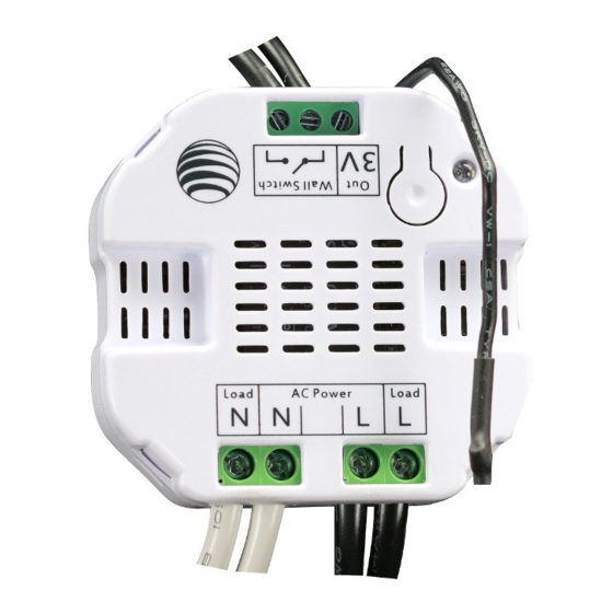
Preparing and Connecting Wires
Step 3
The Aeotec Micro Smart Energy Switch G2 must first be powered
by a 3-wire system in order to operate. The wiring diagram
is as follows:
all
Note: The "3V Out" terminal should be used only with the Aeon
Micro Touch.
Cut wire if
neccessary
Diagram
Load
AC Power
Load
Load
N
N
L
L
1. Live - Hot wire (Black wire) Connect to Live terminal of Micro Smart Energy Switch G2.
2. Neutral (White wire) Note! If this wire is not present in the box, a neutral wire must
be pulled into the box.
3. Load wire - Connect to Load terminal of Micro Smart Energy Switch G2.
knowledge
and
4. Signal connection - Using two
18 AWG copper wires, connect
the terminals of the wall switch
to Micro Smart Energy Switch
G2 as shown.
5. Side wire connection
2
1
3
Mounting In Wall Box.
Step 4
ON
1. Position all wires to provide room for the device. Place Micro Smart
Energy Switch G2 inside the wall box towards the back of the box.
ON
2. Position the antenna towards the back of the box, away from all other
wiring.
ON
3. Reinstall the wall switch to the wall box.
ON
4. Reinstall the cover plate onto the wall box.
1
2
Restore Power
Step 5
1
Restore power at the circuit breaker or fuse.
Installation is complete.
Z-Wave Network Instructions:
The Aeotec Micro Smart Energy Switch G2 must be paired
(included) into a Z-Wave network before it can receive
Z-Wave commands to turn on/off and report its energy usage.
The Micro Smart Energy Switch G2 can only communicate
to devices within it's own Z-Wave network.
0.27"
Strip Gage
(7mm)
(measure bare
Note: The LED on the Micro Smart Energy Switch G2 will
here)
blink if it is currently not paired into a Z-Wave network.
Adding/Including/Pairing the Micro Smart Energy
Switch G2 into a Z-Wave Network
Load
AC Power
Load
Load
N
N
L
L
Include
Note: To include the Aeotec Micro Smart Energy Switch G2
with other controllers, please consult the operation manual
for these controllers on how to include Z-Wave products
into an existing network.
Make sure that the ends of the wires from the
wall box are straight (cut if neccessary).
While the Micro Smart Energy Switch G2 is powered in a 3-wire
2
system, the external switch/button can be toggled to initiate
Remove insulation from each wire and the wall
pairing into the Z-Wave network. Or the internal button can be
box as shown.
pushed to initiate pairing into the Z-Wave network if the Micro
Smart Energy Switch G2 was not put into in-wall box.
4
5
Load
AC Power
Load
Load
N
N
L
L
Troubleshooting: If the Aeotec Micro Smart Energy Switch G2 was
not successfully included into any Z-Wave network, the LED will continually
blink slowly. If the Aeotec Micro Smart Energy Switch G2 was
successfully included to a Z-Wave network, the Status Indication LED
will either be solid on or off depending on if the switch is on or off.
3
4
2
4
Remove
Note: To remove the Aeotec Micro Smart Energy Switch
G2 from other controllers, please consult the operation
ON
ON
manual for these controllers on how to remove Z-Wave
ON
ON
products from an existing network.
ON
ON
While the Micro Smart Energy Switch G2 is powered in a 3-wire
ON
ON
2
system, the external switch/button can be toggled 10 times in
ON
ON
quick succession to initiate removing from the Z-Wave network.
Or the internal button can be pushed to initiate pairing into the
ON
ON
Z-Wave network if Micro Smart Energy Switch G2 was not put
ON
ON
into in-wall box.
Troubleshooting: If the Aeotec Micro Smart Energy Switch G2 was
removed from the Z-Wave network, the Status Indication LED will be
blinking. If the Aeotec Micro Smart Energy Switch G2 was not successfully
removed from the Z-Wave network, the Status Indication LED will either
be solid on or off depending on if the switch is on or off.
Note: If Micro Smart Energy Switch G2 was not put into in-wall box,
1
Press the button labeled "Include" on
Another way to reset Aeotec Micro Smart Energy Switch G2 is
the Aeotec Minimote to begin the
pressing and holding the button which is on Micro Smart Energy
Z-Wave inclusion process.
Switch G2 20 seconds.
Removing/Resetting the Micro Smart Energy
Switch G2 from your Z-Wave Network
1
Press the button labeled "Remove" on
the Aeotec Minimote to begin the Z-Wave
removal process.
Advertisement

Summary of Contents for Aeotec Micro Switch G2
- Page 1 Troubleshooting: If the Aeotec Micro Smart Energy Switch G2 was Acting as a bridge for communication, it will removed from the Z-Wave network, the Status Indication LED will be blinking. If the Aeotec Micro Smart Energy Switch G2 was not successfully forward Z-Wave command messages to their Diagram...
- Page 2 PURPOSE. via 2-state(flip/flop) external wall switch by default. Pushing and Aeotec does not authorize any person or party to assume or create for it holding the button 6 seconds on the Micro Smart Energy Switch G2 any other obligation or liability in connection with the Products except as will swap between this default mode and the momentary push button set forth herein.
Need help?
Do you have a question about the Micro Switch G2 and is the answer not in the manual?
Questions and answers