Table of Contents

Related Manuals for Apogee SQ-520


Summary of Contents for Apogee SQ-520
-
Page 1: Owner's Manual
OWNER’S MANUAL USB QUANTUM SENSOR Model SQ-520 APOGEE INSTRUMENTS, INC. | 721 WEST 1800 NORTH, LOGAN, UTAH 84321, USA TEL: (435) 792-4700 | FAX: (435) 787-8268 | WEB: APOGEEINSTRUMENTS.COM Copyright © 2016 Apogee Instrument, Inc. -
Page 2: Table Of Contents
TABLE OF CONTENTS Owner’s Manual ..........................................1 Certificate of Compliance......................................3 Introduction ..........................................4 Sensor Models ..........................................5 Specifications ..........................................6 Deployment and Installation ....................................9 Software Installation ......................................... 10 Operation and Measurement ....................................10 Windows Software ........................................14 Mac Software ..........................................19 Maintenance and Recalibration .................................... -
Page 3: Certificate Of Compliance
(PBB), polybrominated diphenyls (PBDE). Further note that Apogee Instruments does not specifically run any analysis on our raw materials or end products for the presence of these substances, but rely on the information provided to us by our material suppliers. -
Page 4: Introduction
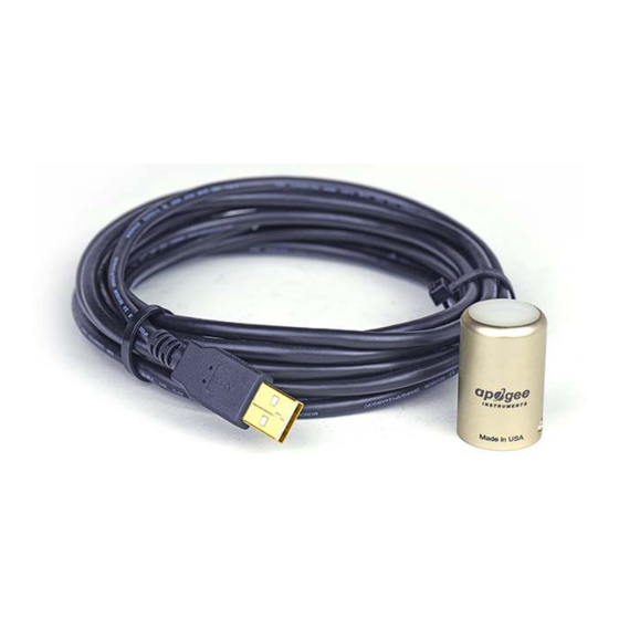
(transmitted) PPFD measurement in the same environments. Apogee Instruments SQ series quantum sensors consist of a cast acrylic diffuser (filter), photodiode, and signal processing circuitry mounted in an anodized aluminum housing, and a cable to connect the sensor to a measurement device. SQ-500 series quantum sensors are designed for continuous PPFD measurements in indoor or outdoor environments. -
Page 5: Sensor Models
SENSOR MODELS This manual covers the USB quantum sensor model SQ-520. For additional models see SQ-100/SQ-300 series, SQ-212/SQ-222 and SQ-215/SQ-225, and SQ-214/SQ-224 manuals. Model Signal SQ-520 SQ-500 Self-powered Sensor model number and serial number are located near USB connector. If you need the... -
Page 6: Specifications
Apogee Instruments SQ-500 series quantum sensors are calibrated through side-by-side comparison to the mean of four Apogee model SQ-500 transfer standard quantum sensors under high output T5 cool white fluorescent lamps. The transfer standard quantum sensors are calibrated through side-by-side comparison to the mean of at least three LI-COR model LI- 190R reference quantum sensors under high output T5 cool white fluorescent lamps. - Page 7 Spectral Response Mean spectral response measurements of six replicate Apogee SQ-100 and SQ-500 series quantum sensors. Spectral response measurements were made at 10 nm increments across a wavelength range of 300 to 800 nm in a monochromator with an attached electric light source.
- Page 8 Cosine Response Directional, or cosine, response is defined as the measurement error at a specific angle of radiation incidence. Error for Apogee SQ-500 series quantum sensors is approximately ± 2 % and ± 5 % at solar zenith angles of 45° and 75°, respectively.
-
Page 9: Deployment And Installation
Mount the sensor to a solid surface with the nylon mounting screw provided. To accurately measure PPFD incident on a horizontal surface, the sensor must be level. An Apogee Instruments model AL-100 leveling plate is recommended for this purpose. To facilitate mounting on a cross arm, an Apogee Instruments model AM-110 mounting bracket is recommended. -
Page 10: Software Installation
SOFTWARE INSTALLATION The most recent version of ApogeeConnect software can be downloaded at http://www.apogeeinstruments.com/downloads/. Installing the software on a PC (Windows compatible, XP and later) Double click on the installer package: On the ‘Welcome’ screen, please click ‘Next’ to continue. Select the radio button next to “I Agree”... -
Page 11: Operation And Measurement
SQ-100 series sensors because the SQ-500 spectral response is a closer match to the defined plant photosynthetic response. Spectral Errors for PPFD and YPFD Measurements with Apogee SQ Series Quantum Sensors SQ-100 Series SQ-500 Series... - Page 12 (black line, defined plant response to radiation), YPFD (blue line, measured plant response to radiation), and Apogee SQ-500 Series Quantum Sensors (green line, sensor sensitivity to different wavelengths of radiation). One potential definition of PAR is weighting photon flux density [µmol m ] at each wavelength between 300 and 800 nm by relative quantum yield and summing the result.
- Page 13 Without correcting for this effect, underwater measurements are only relative, which makes it difficult to compare light in different environments. The SQ-520 sensor has an immersion effect correction factor of 1.32. The immersion effect correction factor can be automatically applied to SQ-520 measurements by turning on the immersion setting in the settings option of the ApogeeConnect software, as pictured.
-
Page 14: Windows Software
WINDOWS SOFTWARE When the SQ-520 sensor is not plugged into the USB port, the software will display a message in the lower left corner, “Device Not Connected,” indicating it cannot establish communication with the sensor. Plug the sensor into a USB port and allow some time for the sensor to automatically establish communication with the software. - Page 15 Click the ‘Settings’ icon to display the software options. Note ‘Light Source’ is not a selectable option. The SQ-520 is calibrated for all light sources, therefore, this function is not necessary for the SQ-520. The function is designed to give increased accuracy for the SQ-420.
- Page 16 After clicking the ‘Recalibate’ button the user will be prompted to cover the sensor. Place a dark cap over the sensor and wait for the real-time PAR reading to settle at zero. Click OK. Uncover the sensor and wait for the PAR reading to settle before entering the reference value.
- Page 17 The about screen tells you the software and firmware versions. These can be used to help troubleshoot if problems arise. ‘Manage Field Logging’ is used to setup the SQ-520 for use in the field. When the SQ-520 is supplied power from a USB power source (plug or select batteries) it will log data which you can retrieve.
- Page 18 Click ‘Erase Data’ to erase all the saved data. This can’t be undone. To use additional SQ-520 devices, open additional SQ-520 software windows. The device serial number will display in the lower left hand corner of the corresponding software window. Devices may be selected by serial number in the tool bar.
-
Page 19: Mac Software
MAC SOFTWARE When the SQ-520 sensor is not plugged into the USB port, the software will display a message in the lower left corner, “Device Not Connected,” indicating it cannot establish communication with the sensor. Plug the sensor into a USB port and allow some time for the sensor to automatically establish communication with the software. - Page 20 Click the ‘Settings’ icon to display the software options. Clicking ‘Light Source’ will allow the user to change the sensor’s default calibration reference from Electric to Sunlight. Electric should be selected when measuring most indoor artificial light sources, while Sunlight should be selected when measuring sunlight (such as when evaluating the need for recalibration).
- Page 21 Clicking ‘Calibration’ will display the factory calibrated multiplier and offset values. These values are saved in firmware and can be recovered by clicking the ‘Recover Original’ button. Deriving a new calibration multiplier and offset is accomplished by clicking the ‘Recalibrate’ button. This is applicable if users want to calibrate the sensor to their own specific light source.
- Page 22 Clicking ‘Data Logging’ will allow the user to log interval measurements in a csv file while the software is open and communicating with the sensor. Click ‘Setup’ and the Setup Logging window appears. Click the ‘Browse button to create or select a csv file. Select the desired sampling interval.
- Page 23 Click ‘Erase Data’ to erase all the save data. This can’t be undone. To use additional SQ-520 devices, open additional SQ-520 software windows. The device serial number will display in the lower left hand corner of the corresponding software window. Devices may be selected by serial number in the tool bar.
-
Page 24: Maintenance And Recalibration
MAINTENANCE AND RECALIBRATION Moisture or debris on the diffuser is a common cause of low readings. The sensor has a domed diffuser and housing for improved self-cleaning from rainfall, but materials can accumulate on the diffuser (e.g., dust during periods of low rainfall, salt deposits from evaporation of sea spray or sprinkler irrigation water) and partially block the optical path. - Page 25 Homepage of the Clear Sky Calculator. Two calculators are available: one for quantum sensors (PPFD) and one for pyranometers (total shortwave radiation). Clear Sky Calculator for quantum sensors. Site data are input in blue cells in middle of page and an estimate of PPFD is returned on right-hand side of page.
-
Page 26: Troubleshooting And Customer Support
Knowledge Base on the Apogee website (http://www.apogeeinstruments.com/knowledge-base/; scroll down to Quantum Sensors section). A spreadsheet to convert PPFD to energy flux density or illuminance is also provided in the Knowledge Base on the Apogee website (http://www.apogeeinstruments.com/content/PPFD-to-Illuminance-Calculator.xls). -
Page 27: Return And Warranty Policy
RETURN AND WARRANTY POLICY RETURN POLICY Apogee Instruments will accept returns within 30 days of purchase as long as the product is in new condition (to be determined by Apogee). Returns are subject to a 10 % restocking fee. WARRANTY POLICY... - Page 28 5. Upon receipt, Apogee Instruments will determine the cause of failure. If the product is found to be defective in terms of operation to the published specifications due to a failure of product materials or craftsmanship, Apogee Instruments will repair or replace the items free of charge.
Need help?
Do you have a question about the SQ-520 and is the answer not in the manual?
Questions and answers