
Summary of Contents for Spire 4 Technologies SUN-RAC SRTP-PM-1
- Page 1 PV-MODULE MOUNTING TP SUN-R AC LT SERIES INSTALLATION MANUAL FOR 4.0" SCH 40 REV1.120518...
-
Page 2: Table Of Contents
Spire 4 Technologies info@spire4.com www.spire4.com Spire 4 Technologies info@spire4.com www.spire4.com CONTENT — 1.SUN-RAC GENERAL REFERENCES …………………………………………..… PAGE 3 2.ADDITIONAL INSTALLATION ITEMS – PIPE DIMENSIONS ……………..…. PAGE 3-4 3.PARTS LIST …………………………………………………………………………. PAGE 4-5 4.PLANNING …………………………………………………………………………. PAGE 5-6 “The SUN-RAC system is the fastest most cost effective top 4.2 REQUIRED TOOLS ………………………………………………………..….. -
Page 3: Sun-Rac General References
Spire 4 Technologies info@spire4.com www.spire4.com Spire 4 Technologies info@spire4.com www.spire4.com S U N - R A C Cross Beam Lengths Minimum SRTP-PM-X LT SERIES // Lengths shown below. (See 5.3 for exact calculations) 1 - SUN-RAC GENERAL REFERENCES BEAM PM-1... -
Page 4: Planning
Spire 4 Technologies info@spire4.com www.spire4.com Spire 4 Technologies info@spire4.com www.spire4.com INSTALLING RACKING SYSTEM. Assumptions: The pole extends no more than 6 feet(1.8 meters) above ground, Design wind speeds assume 29 psf wind force at 90mph (150km/h) and 51 psf wind force at 120 mph(200km/h).which correspond to Exposure Category C of the International Building... -
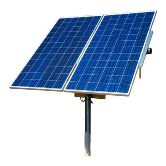
Page 5: Mounting
Spire 4 Technologies info@spire4.com www.spire4.com Spire 4 Technologies info@spire4.com www.spire4.com 5 - MOUNTING 5.4 INSTALLATION OF THE SUN-RAC TOP POLE-MOUNT PM-1-X The Pole Mount SRTP-PM-1-x is designed to require minimum servicing or maintenance work. For safe and Parts of the mounting system are very heavy so care must be taken during handling, un- reliable operation the system should be checked regularly. - Page 6 Spire 4 Technologies info@spire4.com www.spire4.com Spire 4 Technologies info@spire4.com www.spire4.com 4. Lay the Beam on the Cap. 7. Mount one of the Purlin at a Tilt-angle of 0° The W= Panel’s Width+24mm[0.95 inch] 5. Place the Cross Beam Bracket under the Beam, insert the U-bolt (6) into the holes and through the Rack Head, connect M10 washers and lock washers ②...
- Page 7 Spire 4 Technologies info@spire4.com www.spire4.com Spire 4 Technologies info@spire4.com www.spire4.com 8.Installed the Solar Panel on the Purlin②. a. installed the First Panel (start on either end) with the End Clamp( M8*25 Bolt & Spring washer). 5.5 ADJUSTMENT OF THE TILT-ANGLE b.
- Page 8 Spire 4 Technologies info@spire4.com www.spire4.com Spire 4 Technologies info@spire4.com www.spire4.com NOTES ON INSTALLATION: Make sure that a galvanized steel pipe is used so that all rust and corrosion is inhibited. If galvanized pipe is not used, make sure that all exposed steel surfaces are painted for the environmental conditions presented.
- Page 9 Simply. Energy. © 2016 All Rights Reserved.
Need help?
Do you have a question about the SUN-RAC SRTP-PM-1 and is the answer not in the manual?
Questions and answers