Table of Contents
Advertisement
Advertisement
Table of Contents

Summary of Contents for Ablerex Buck 1000W
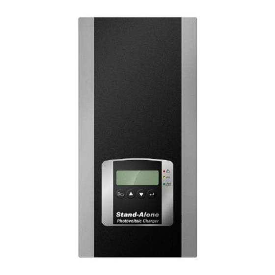
- Page 1 Photovoltaic Charger Buck – 1000W/1500W 12/24/36/48 Vdc User’s Manual...
-
Page 2: Table Of Contents
Content IMPORTANT NOTES ......................3 1.0 I ......................4 NTRODUCTION 1.1 I ....................5 NSTALLATION 1.2 I ......................6 NSTALLATION 1.3 A ......................7 CCESSORIES 1.4 LED I ................8 NDICATION XPLANATIONS 2.0 LCD D .....................9 ESCRIPTION 2.1 O .........................9 PERATION 2.1.1Enter into Setting Mode ........................12 2.1.2Battery Capacity(AH) Setting ...................... -
Page 3: Important Notes
Important Notes 1. Keep this user’s manual and follow all instructions indicated in the manual. 2. Don’t overload the charger. 3. Don’t split the charger apart; otherwise, your warranty is void. 4. Only authorized technician may repair or replace the interior components. 5. -
Page 4: Introduction
1.0 Introduction BUCK-1000/1500W photovoltaic charger is to convert the energy from solar panel to load or batteries connected. With different load or batteries connected, it can be set as 12V, 24V, 36V or 48V system. The solar charger can get max. efficiency up to 95%. The solar cells can get the highest efficiency by means of Maximum Power Point Tracking(MPPT) and pulse charge method.. -
Page 5: Installation Site
Battery temperature sensor automatically provides temperature compensated battery charging. Provide communication software to monitor the status of the charger. Smart fan speed Control according to the load connected. This intelligent charger may set output voltage automatically or user may select output voltage 12/ 24 /36/ 48 V via LCD panel。... -
Page 6: Installation
Figure 3: Installation Site 1.2 Installation Please remove the wiring compartment cover for installation as illustrated below. After installation, please fasten the cover back to its original position. Figure 4: Disassemble Wiring Compartment Cover Figure 5: Cabling Contact Description To the positive(+) of solar cell To negative(-) of solar cell Bat+ To the positive(+) of Bat. -
Page 7: Accessories
Load+ To the positive(+) of Load Load- To the negative(-) of Load Battery Temperature Sensor Ground ■ Recommended Installation Sequence: Connect Load → Battery → Solar Cell ■If there is no load connected Connect Battery → Solar Cell ■Make sure the BTS wire is installed and fixed to the contact (CN11). ■Make sure the Battery and load are removed before entering into setting mode. -
Page 8: Led Indication Explanations
3.Connecting terminal to the solar panel(phi4-female) × 1 1.4 LED Indication Explanations Figure 6: Bottom View Description Fault System Fault, Protection Circuit is (Red) activated. PV Low Under-voltage/Over-voltage of (Amber) Solar Cell Normal System Operation in Normal (Green) RS232 RS232 Communication Interface... -
Page 9: Lcd Description
2.0 LCD Description Item Symbol Description System Fault, Charger goes to “Protection Mode” Error code shown on the LCD Under-voltage/Over-voltage of Solar Cell Charging Mode –Illuminate / Load Mode - Flash Function Key (Left: push slightly; Return: push heavily) Scroll Key-Up Scroll Key-Down Function Key (Right: push slightly;... - Page 10 Approx. 3 seconds later, the LCD display will show as drawing B and the charger is under initialization. When the charger is in normal operation, it shows the current input voltage of the solar panel as shown in drawing C, then the green LED lights up to indicate that the charger is connected with batteries and also charges to the batteries.
- Page 11 After turning on the PV charger, it will display current solar cells’ voltage. If you would like to see other parameters, you may press key or key. Caution: keys are of no use. You may press key to scroll up and down to get different display information and message.
-
Page 12: 1Enter Into Setting Mode
2.1.1Enter into Setting Mode Make sure the output voltage and capacity of the battery are set properly. Caution! Before entering into setting mode, make sure the battery and the load are removed; otherwise, it might damage the battery and the load due to improper setting. Step1: Make sure the charger is connected with solar cell with 40V~150Vdc voltage and do not turn on the charge. -
Page 13: 2Battery Capacity(Ah) Setting
2.1.2Battery Capacity(AH) Setting Step1: It indicates the current battery capacity when getting into Battery Capacity setting. Step2: Select desired battery capacity (AH) by scroll key or key. The digit with flashing cursor means the desired one to be changed. If you would like to change the left-hand/right-hand digit, you may press key or respectively. -
Page 14: Battery Over-Voltage Limit Setting
Step2: To select other battery voltage by scrolling key and key. Step3: Battery voltage can be set as 12V, 24V, 36V, 48V or Auto. When the desired voltage is selected, please press key to save till “SAVE” shown on the screen. -
Page 15: Battery Under-Voltage Limit Setting
Step4: If you would like to escape from battery over- and under- voltage setting, please press key to escape. 2.1.5 Battery Under-Voltage Limit Setting In normal condition, it is not necessary to calibrate this setting as long as the battery voltage selected is within window. -
Page 16: Parallel Address Setting
Step1: Step1: Enter into Pulse Charge Setting. If it shows “ON” it means the charger is able to be in Pulse Charge; on the contrary, it means the charger is not able to be in Pulse Charge if it shows “OFF”. Step2: You may select “ON”... -
Page 17: Parameters Displayed
left-hand figure, you may press key and the right-hand figure, you may press key. Step3: The range of the total input power can be selected from 0~999K KWH. Once the figure is selected, you may press key to save. Make sure the “SAVE” shown on the screen, then you may release key now. - Page 18 Battery Voltage Current supplied to Battery Current Battery Capacity Setting Battery Temperature in Celsius IGBT temperature in Celsius Battery Temperature in Fahrenheit IGBT temperature in Fahrenheit Battery Capacity Setting Directory Battery Voltage Setting Directory Battery Over-voltage Setting Battery Under-voltage Setting Pulse Charge Setting Parallel Address Setting Total Input Power(KWH)
-
Page 19: Error Codes
2.3 Error Codes When the charger can not work normally, it will show the error code on the LCD display as Table 1. You may proceed troubleshooting indicated as below. Error Code Description Trouble Shooting AL04 Input Over-voltage Reduce input voltage AL05 Input Under-voltage Increase input voltage... -
Page 20: Product Specifications
3.0 Product Specifications Models Buck-1000W Buck-1500W Input Rated Voltage 40~120Vdc 40~120 Vdc @ 12Vbat Operating Voltage / 40~120 Vdc @ 24Vbat MPPT Range 50~120 Vdc @ 36Vbat 60~120 Vdc @ 48Vbat Max. Input current 25 A 35 A Max. PV Array Open 150 Vdc Circuit Voltage Max. - Page 21 0-2000M up to 60℃; 0~3000M up to 55℃ Altitude Humidity 100% RH Maximum, No Condensing INTERFACE COMPUTER Type Standard RS232 COMPLIANCE Quality ISO9001 Standard EMC EN61000-6-1, EN61000-6-3 Marking Patent Pending Taiwan: 97147246 Part No. China: 200810180491.7 USA: 12/273,669...
- Page 24 192321452000000...
Need help?
Do you have a question about the Buck 1000W and is the answer not in the manual?
Questions and answers