Table of Contents
Advertisement
Advertisement
Table of Contents

Summary of Contents for Parasound Halo JC 5
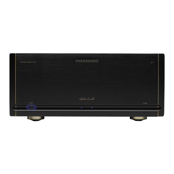
- Page 1 JC 5 Stereo Power Amplifier OWNER’S GUIDE...
-
Page 2: Important Safety Instructions
Important Safety Instructions The lightning flash with the arrowhead symbol within an equilateral triangle is intended to alert the user to the presence of “dangerous voltage” inside the product that may constitute a risk of electric shock. The exclamation point within an equilateral triangle is intended to alert the user to the presence of important operating and maintenance instructions in the literature accompanying the product. -
Page 3: Table Of Contents
Table of Contents Introduction ..........Placement and Ventilation Guidelines . -
Page 4: Introduction
Parasound is renowned. We’re proud to offer you this exceptional audio component that will bring you many years of enjoyment and dependability. We designed your new Halo JC 5 Amplifier to perform at a higher level of sonic performance than you may have expected and we encourage you to read this entire manual to maximize your enjoyment. -
Page 5: Placement And Ventilation Guidelines
AC Voltage Reconfiguring Technical Information Parasound will provide technical information which pertains to the interior of this amplifier only to a qualified electronics technician. This restriction is for your safety as well as the correct functioning of your amplifier. -
Page 8: Rack Mounting
Please call your Parasound dealer or Parasound Technical Services if you need additional advice about rack mounting the JC 5. Keep the above Note and Warning... -
Page 9: Audio Connections
Audio Connections Always disconnect the AC cord to your JC 5 before making or changing any input, output or trigger wire connections. Inserting or removing an input or output cable while the JC 5 is turned on can result in a blast of sound that can damage your loudspeakers. -
Page 10: Bi-Amping
Speaker Connections for Bridged Mode When operating in bridged mono mode a JC 5 should only power a single 8 ohm speaker. Connect the speaker’s positive (+) speaker wire to the JC 5’s right channel positive (+) speaker terminal. Connect the speaker’s negative (-) wire to the JC 5’s left channel positive (+) speaker terminal. Correct + and speaker polarity for bridged mode is shown below the JC 5 speaker terminals. -
Page 11: Turn On Options
Correct Speaker Polarity is Important Polarity refers to + and – connections. Speaker wires are coded with color, printing or a ridge on the insulation on one of the leads so you know which lead was connected to the + and – terminals at the other end. This coding will help you keep the + and - polarity consistent for all channels. -
Page 12: Front Panel Operation
3.5 mm vs. 2.5 mm jacks Some other Parasound power amplifiers and preamplifiers might use a 2.5 mm “sub-mini” (mono) trigger jack. To use the JC 5 trigger with products that use a 2.5mm jack you will need a 3.5 mm to 2.5 mm mono adapter... -
Page 13: Technically Speaking
1. Your Cable TV or Satellite receiver box might require a Cable TV Ground Isolator. 2. Use balanced input cables with your Parasound JC 5. (See Balanced & Unbalanced Lines in this section). 3. When rack mounting, always use the insulated “shoulder” washers on both the front and rear sides of the... -
Page 14: Design Overview
As our featured amplifier designer since 1990, he has created many products that have earned Parasound worldwide acclaim, including the Parasound Halo JC 1, JC 2 and JC 2 BP, JC 3, JC 3+ and JC 3 Jr.. John is particularly proud of what he and Parasound have accomplished together: “The circuits I design for Parasound are extremely sophisticated and are typical of products that are far more expensive. - Page 15 JC 5 is in full operation. Audio Circuit Path Topology Parasound’s circuit topology is a hybrid of carefully chosen discrete transistors that result in superior performance at each stage. We use JFETs (Junction Field Effect Transistors) for the input voltage amplifier stage;...
- Page 16 “veil” sonic clarity and attenuate bass response. Parasound power amplifiers incorporate ingenious and fast-acting DC servo circuits, completely eliminating the need for coupling and blocking capacitors. The JC 5 is direct (DC) coupled from its input jacks to its speaker terminals.
-
Page 17: Problems And Remedies
Problems and Remedies Unit will not turn on • Check the setting of the Turn On Options switch. (The front panel On-Off button will be disabled if this switch is set to Audio or 12 V) • If using Audio Turn on, try increasing the sensitivity of the audio trigger by turning the audio threshold knob to the “Quieter”... -
Page 18: If You Require Assistance Or Warranty Repair
Are You Having Difficulty? Repair or Service Call your Parasound dealer first. If the dealer can’t help you with your problem we encourage you to call Parasound’s Technical Service Department at 415-397-7100, Monday - Friday, 8am - 4pm Pacific Time. We can suggest other diagnostic tests you can easily perform. -
Page 19: Chassis Illustration And Dimensions
Chassis Illustration and Dimensions... -
Page 20: Specifications
Typical Listening levels: 400 Watts Maximum: 1500 Watts Specifications and features subject to change or improvement without notice. Copyright Parasound Product Inc., 2018, Rev. 1.0 Parasound Products, Inc. 2250 McKinnon Ave, San Francisco, CA 94124 415-397-7100 / Fax 415-397-0144 www.parasound.com...


Need help?
Do you have a question about the Halo JC 5 and is the answer not in the manual?
Questions and answers