Table of Contents
Advertisement
INSTALLATION AND OPERATING INSTRUCTIONS
KB Part No. 8840 (Black Case) • Part No. 8841 (White Case)
Rated for 1/10 - 1 HP (90 Volts DC) @ 115 Volts AC, 50/60 Hz
and 1/5 - 2 HP (180 Volts DC) @ 208/230 Volts AC, 50/60 Hz
The information contained in this manual is intended to be accurate. However, the manufacturer retains
Spec Tech Industrial 203 Vest Ave. Valley Park, MO 63088 Phone: 888 SPECTECH
Email: sales@spectechind.com
MODEL KBRC-240D
FULL-WAVE 4-QUADRANT REGENERATIVE DRIVE
NEMA 4X, IP-65
Washdown and Watertight for Indoor and Outdoor Use
!
See Safety Warning on Page 5
the right to make changes in design which may not be included herein.
A COMPLETE LINE OF MOTOR DRIVES
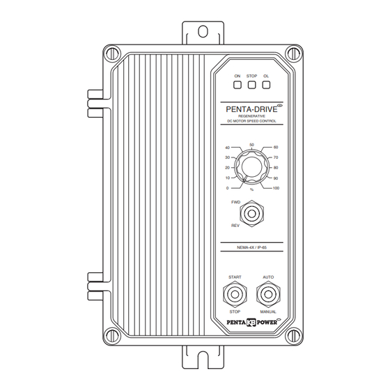
ON
STOP
OL
PENTA-DRIVE
TM
REGENERATIVE
DC MOTOR SPEED CONTROL
50
40
60
30
70
20
80
10
90
0
100
%
FWD
REV
NEMA-4X / IP-65
START
AUTO
STOP
MANUAL
TM
© 2003 KB Electronics, Inc.
www.spectechind.com
Pending
Advertisement
Table of Contents

Subscribe to Our Youtube Channel
Summary of Contents for KB Electronics Penta KB Power KBRC-240D
- Page 1 The information contained in this manual is intended to be accurate. However, the manufacturer retains the right to make changes in design which may not be included herein. A COMPLETE LINE OF MOTOR DRIVES © 2003 KB Electronics, Inc. Spec Tech Industrial 203 Vest Ave. Valley Park, MO 63088 Phone: 888 SPECTECH Email: sales@spectechind.com...
-
Page 2: Table Of Contents
TABLE OF CONTENTS Section Page Simplified Operating Instructions ......... . 4 Safety Warning . - Page 3 15. DC Tach-Generator Connection ......... . 14 16.
-
Page 4: Simplified Operating Instructions
SIMPLIFIED OPERATING INSTRUCTIONS IMPORTANT – You must read these simplified operating instructions before pro- ceeding. These instructions are to be used as a reference only and are not intended to replace the detailed instructions provided herein. You must read the Safety Warning, on page 5, before proceeding. -
Page 5: Safety Warning
8842] or equivalent). INTRODUCTION Thank you for purchasing the KBRC-240D. KB Electronics, Inc. is committed to providing total customer satisfaction by producing quality products that are easy to install and operate. The KBRC-240D is manufactured with surface mount components incorporating advanced circuitry and technology. -
Page 6: General Performance Specifications
Potentiometer rotation or input signal. In the Non-Linear Torque mode (NL), the torque is var- ied by the Main Speed Potentiometer or input signal, and remains constant throughout the motor’s entire speed range. In addition, Regenerate-to-Stop (RTS) or Coast-to-Stop (CTS) stop modes are also provided. -
Page 7: Control Layout
FIGURE 1 – CONTROL LAYOUT (Illustrates Factory Setting of Jumpers and Approximate Trimpot Settings) OFFSET RACC FACC FWDCL REVCL RESP RELAY LED BOARD NTCL CON1 PWR ON 115V 230V 230V 115V KBRC F1 TB2 FIGURE 2 – ENLARGED VIEW OF TRIMPOTS OFFSET RACC FACC FWDCL... -
Page 8: Mechanical Specifications
FIGURE 3 – MECHANICAL SPECIFICATIONS (Inches / [mm]) -
Page 9: Wiring Instructions
STANDARD FEATURES A. Short Circuit Protection – Protects the control from a short circuit at motor connections. B. Electronic Motor Burnout Protection (I X t) – Shuts down the control if a prolonged overload condition exists. C. Start/Stop Switch – Provides electronic start/stop function. D. -
Page 10: Power Connections
Warning! Do not wire switches or relays in series with the armature. Armature switch- ing can cause catastrophic failure of motor and/or control. To avoid erratic operation, do not bundle AC line and motor wires with potentiometer wires, voltage following wires, Start/Stop Switch wires, enable wires, or any other signal wires. -
Page 11: Field Connection (Shunt Wound Motors Only)
Note: Do not connect motor armature leads to F1 and F2 quick-connect terminals. Do not use F+ and F- terminals of Terminal Block TB2 for any purpose other than to power the field of a shunt wound motor. E. Half Voltage Field Connection (Shunt Wound Motors Only) – Wire the motor field leads to F+ terminal of Terminal Block TB2 and L1 terminal of Terminal Block TB1, as shown in Figure 6, on page 10 and as described in Table 4. -
Page 12: Bidirectional Main Speed Potentiometer Connection
FIGURE 9 – BIDIRECTIONAL MAIN SPEED 3. Bidirectional Operation – POTENTIOMETER CONNECTION Provides forward and reverse operation using the Main Speed LOW (WHITE) Potentiometer. Connect WIPER (ORANGE) Main Speed Potentiometer high HIGH (VIOLET) side to +15V terminal, wiper to SIG terminal and low side to MAIN SPEED -15V terminal, as shown in POTENTIOMETER... -
Page 13: Run Relay Output Contacts
TABLE 5 – RUN RELAY OUTPUT CONTACTS H. Run Relay Connection – Normally open (NO) or normally closed (NC) JUMPER J10 RUN RELAY MODE relay output contacts are available at POSITION CONTACTS Terminal Block TB3, which change Closed state when the Start/Stop Switch is Open set to the “START”... -
Page 14: Iii. Setting Selectable Jumpers
the motor armature voltage. If the tach-generator polarity is reversed, the motor will accelerate to full speed and the Main Speed Potentiometer will not control speed. Tach- generator feedback can greatly improve speed regulation and dynamic response. Note: When using a tach-generator, the IR trimpot should be set fully counterclockwise. Note: The tach-generator input is designed for 7 Volt or 50 Volt per 1000 RPM tach-gen- erators used with 1800 RPM motors. -
Page 15: Setting Motor Current
Note: If Jumper J3 is set to the “T7” or “T50” position, a tach-generator must be wired to Terminal Block TB3. If a tach- generator is not used, Jumper J3 must be in either the “A180” or “A90” position. If jumper J3 is in the “T7” or “T50” position, and a tach-gener- ator is not used, the motor will accelerate to full speed and the Main Speed Potentiometer will not control speed. -
Page 16: Control Mode Selection (J6)
FIGURE 22 – CONTROL MODE F. Control Mode Selection (J6) – Jumper J6 SELECTION is factory set to the “SPD” position for Speed Control Mode . For Torque Control J6 Set for J6 Set for Speed Control Mode Mode, set Jumper J6 to the “TRQ” posi- Torque Control Mode (Factory Setting) tion. -
Page 17: Iv. Mounting Instructions
FIGURE 27 – ENABLE JUMPER K. Enable Jumper (J11) – Jumper J11 is fac- tory installed to enable the control. J11 Installed for J11 Not installed for Auto-Enable installing the Enable Circuit, as described Manual Enable (Factory Setting) in Section IIJ, on page 13, remove Jumper J11. -
Page 18: Vi. Operation
C. The hi-pot test voltage should be set in accordance to the testing agency standards and the leakage current should be set as low as possible without causing nuisance trips. D. To eliminate motor speed control damage due to auxiliary equipment hi-pot failure, it is also recommended that all signal inputs be wired together and connected to the AC input lines as shown. -
Page 19: Viii. Trimpot Adjustments
FIGURE 31 – OFFSET VIII. TRIMPOT ADJUSTMENTS TRIMPOT RANGE The KBRC-240D contains trimpots which are factory set for most applications. Figure 2, on page 7, illustrates the location of the trim- pots and their approximate calibrated positions. Some applications may require readjustment of the trimpots in order to tailor the control for a specific requirement. -
Page 20: Maximum Speed (Max) Trimpot Range
output (RACC also sets the forward deceleration time). To increase the reverse acceler- ation time, rotate the RACC trimpot clockwise. To decrease the reverse acceleration time, rotate the RACC trimpot counterclockwise. C. Maximum Speed (MAX) – Sets maximum speed of the motor. FIGURE 36 –... -
Page 21: Response (Resp) Trimpot Range
Note: If the IR compensation is too high, unstable (oscillatory) operation will result. If the control is used with a DC tach-generator, the IR trimpot should be set fully counterclock- wise. To Calibrate the IR Trimpot: 1. Run the motor at approximately 30 - 50% of rated speed at no load and measure the actual speed. -
Page 22: Ix. Diagnostic Leds
To reset the control after it has gone into TCL , momentarily set the Start/Stop switch to the “START” position or disconnect and reconnect the AC line. See Figure 43, on page Resetting the Control after TCL – To reset the control after it has gone into TCL, set the Start/Stop switch to the “STOP”... - Page 23 A. Forward-Stop-Reverse Switch (P/N 9485) – Provides motor reversing and regenerative braking. Mounts on the enclosure cover and is supplied with a switch seal to maintain watertight integrity. B. Power On/Off Switch (P/N 9486) – Disconnects the AC line. Mounts on the enclosure cover and is supplied with a switch seal to maintain watertight integrity.
-
Page 24: Limited Warranty
XI. LIMITED WARRANTY For a period of 18 months from the date of original purchase, KB Electronics, Inc. will repair or replace, without charge, devices which our examination proves to be defective in material or workmanship. This warranty is valid if the unit has not been tampered with by unauthorized persons, misused, abused, or improperly installed and has been used in accordance with the instructions and/or ratings supplied.
Need help?
Do you have a question about the Penta KB Power KBRC-240D and is the answer not in the manual?
Questions and answers