Table of Contents
Advertisement
Advertisement
Table of Contents

Summary of Contents for DIEBOLD Service manual
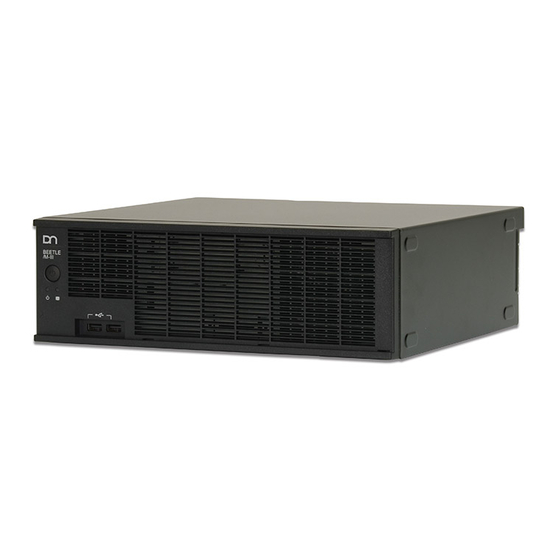
- Page 1 BEETLE /M-III POS Systems K1/K2, M1/M2, O1 Motherboards Service manual...
- Page 2 Any violations give rise to a claim for damages. All rights are reserved, especially rights created by patent grant or registration of a utility model. Subject to availability and technical modifications. All names of hardware and software products mentioned in this manual are trade names and/or trademarks of their respective manufactures. BEETLE /M-III - Service manual...
-
Page 3: Table Of Contents
Settings after the replacement ........................34 Replacing the power supply unit......................38 17.1 For a BEETLE /M-III with UPS ........................40 Inserting memory extensions........................ 50 Replacing the battery..........................52 Changing processors ..........................53 20.1 Installation in headwords..........................56 BEETLE /M-III - Service manual... - Page 4 Interfaces (K1/K2, M1/M2 motherboard)....................85 29.2 Interfaces (O1 motherboard)........................86 29.3 Total current consumption interfaces ......................87 Manufacturer´s Certification......................... 88 30.1 Guarantee ..............................88 30.2 Recycling ..............................88 30.3 FCC-Class A Declaration ..........................88 Abbreviations ............................90 BEETLE /M-III - Service manual...
-
Page 5: Introduction
In these Service instructions it is primarily the removal of components that is described. The installation of these components always proceeds in the reverse order. Special assembly instructions can be found in the respective sections as required. Please read the entire documentation carefully before commencing any repair or maintenance measure. BEETLE /M-III - Service manual... -
Page 6: Important Notes
Clean your system at regular intervals with a dry, lint-free cloth. For greater amounts of soiling, please use a cleaning agent suitable for plastic surfaces, as can be ordered from Diebold Nixdorf International. Make sure that the device is deactivated during cleaning, that the power plug is disconnected and that no fluid enters the inside of the device. - Page 7 Technical Customer Service at Diebold Nixdorf International GmbH or the authorized service partner of your dealer. – An explosion hazard exists if the lithium battery of the device is replaced incorrectly. Only identical batteries or other types recommended by the manufacturer are permitted to be used to replace the lithium battery.
-
Page 8: Installation And Commissioning
– transport damage or inconsistencies between package content and the bill of delivery or function defects, inform your sales outlet of Diebold Nixdorf immediately. Please specify delivery note number, delivery note item number and serial number of the affected device when doing so. The serial number is located on the label shown here on the underside of the housing. -
Page 9: Chassis Components
Rear wall Hood Front cover Hard disk holder Slotted orifice plates EMC sheet metal Air duct (not with a BEETLE/M-III with O1 motherboard) Retail card (not with a BEETLE/M-III with O1 motherboard) Combination module carrier Motherboard BEETLE /M-III - Service manual... -
Page 10: Front View
A BEETLE/M-III is optionally available with a hard disk access in front. LEDs for HDD1/HDD2 The functions of the LEDs are described in the manual for the respective motherboard K1 and K2, M1 and M2, and O1. BEETLE /M-III - Service manual... -
Page 11: Rear View
DVI-D PanelLink2 with RMT Mini DIN keyboard 2 x USB 2.0 RJ45 socket (LAN) 2 x USB 3.0 3 x 3.5 mm jack bush (Audio) Retail Card (3 x PoweredUSB 12 V) 6.1 Rear view with labeling BEETLE /M-III - Service manual... -
Page 12: Rear Side With Ups
Rear view 6.2 Rear side with UPS 6.3 Rear side of O1 motherboard BEETLE /M-III - Service manual... -
Page 13: Setting Up The Device
In cases of installation with cable cover, a distance of 60 mm (2.36") must be maintained behind that cover. The minimum front clearance distance of 50 mm (1.97") must be maintained. The device can be set up on the right or left side. BEETLE /M-III - Service manual... -
Page 14: Cabling The Beetle /M-Iii
– Make sure that the power plug on the rear side of the housing has been pulled out. – Plug in the data cables and secure them. NOTICE Never plug in data or power supply cables when the system is switched on! BEETLE /M-III - Service manual... -
Page 15: Connecting The Device
The power supply unit can be connected to all standard voltage networks. It automatically adjusts itself to the particular voltage. An internal fan provides the necessary cooling. Plug the power cable into the socket on the rear of the device. 1 Power socket BEETLE /M-III - Service manual... - Page 16 Briefly press the On / Off button on the front side of the housing to switch on the device. The LED changes to green in operating mode. 1 On / Off button 2 Power LED BEETLE /M-III - Service manual...
-
Page 17: Assembling The Cable Cover
To install the cable cover, first set the web of the cover on the left side on the rail at the rear side of the BEETLE / M-III. Pull the right side outwards and set this as well on the rail provided for that purpose. 1 Web 2 Rail BEETLE /M-III - Service manual... -
Page 18: Removing The Front Panel
Removing the front panel 10 Removing the front panel To open the front panel, press the unlocking mechanism towards the front. Push the orifice plate to the side (1) and remove it towards the front (2). BEETLE /M-III - Service manual... -
Page 19: Detaching Cables
The interlock is released. The metal of the plug is visible. To disengage an RJ12 plug, press the tab below the plug upwards. Disengage the USB-A plug by pulling on the plug housing. BEETLE /M-III - Service manual... - Page 20 The electrically supplied USB plug is disengaged by pressing on the spring marked with the arrow. Interface connector (COM/DVI/VGA) with knurled screw can be disengaged by hand. To loosen a RJ45 plug, press the tab above the plug (see arrow) downwards. BEETLE /M-III - Service manual...
-
Page 21: Removing The Housing Hood
First, take care to ensure that the device is switched off and that the supply voltage plug is pulled out. Disengage the knurled screws on the rear side of the system. Slide the housing hood somewhat out of the front guide and pull the hood upwards from the housing. BEETLE /M-III - Service manual... -
Page 22: Components Of The System
13 Components of the system 13.1 Inside view 1 Power supply unit 2 Air duct (not with an O1 motherboard) 3 Hard drive carrier 4 Front USB 5 Retail card (not with an O1 motherboard) BEETLE /M-III - Service manual... -
Page 23: Inside View With Ups
2 Air duct (not with an O1 motherboard) 3 Carrier with hard disk(s) (2.5" or 3.5") 4 Accumulator 5 Battery Backup Unit (BBU) 6 Extension board with three PoweredUSB ports (Retail Card), not with a O1 motherboard BEETLE /M-III - Service manual... -
Page 24: Storage Media
Fold open the hard disk carrier upwards and pull the data cable and the power supply cable from the 3.5" hard disk. 1 SATA data cable 2 SATA power supply cable Remove the hard drive carrier. BEETLE /M-III - Service manual... -
Page 25: Sata Connections On K1/K2 Or M1/M2 Motherboard
14.2 SATA connections on K1/K2 or M1/M2 motherboard SATA1 (white) Connection for 3.5" hard disk or for the first 2.5" HDD/SSD SATA2 (blue) Connection for the second 2.5" HDD/SSD SATA3 (black) Connection for CD ROM BEETLE /M-III - Service manual... -
Page 26: Sata Port On The O1 Motherboard
Storage Media 14.3 SATA port on the O1 motherboard SATA (blue) Port for a 3.5“ hard disk or a 2.5“ HDD/SSD BEETLE /M-III - Service manual... -
Page 27: Replacing Two 2.5" Hard Drives Or Ssd
Fold open the hard disk carrier upwards and pull the data cables and the power supply cables from the 2.5" hard disks. 1 SATA data cable 2 SATA power supply cable Remove the hard drive carrier. BEETLE /M-III - Service manual... -
Page 28: For Hard Disks Or Ssd With Front Access
Observe the instructions regarding electrostatic discharge-sensitive assemblies (see chapter "Electrostatic dis- charge-sensitive components"). Remove the front panel (see chapter "Removing the front panel"). Unlock the hard disk holders using the key provided (note the interlock symbols). BEETLE /M-III - Service manual... - Page 29 Storage Media Pull on the green belt to remove the carrier together with the hard disk. Bend the carrier side somewhat outwards and take out the hard disk. No tools are required. BEETLE /M-III - Service manual...
- Page 30 Slide the carrier into the insert point until it engages. Sliding the carrier in causes the hard disk to be connected to the installation board of the plug-in Proceed accordingly when replacing a second hard drive. Lock the hard disk carrier with the key. Insert the front panel. BEETLE /M-III - Service manual...
-
Page 31: Using Photoconductors
Insert the photoconductor from inside into the front panel (1) and press the photoconductor downwards (2). Take care to ensure correct fit of the photoconductor next to the SATA ports on the motherboard. Photoconductor LEDs at the front panel: BEETLE /M-III - Service manual... -
Page 32: Replacing The Accumulator
Remove the cable cover at the rear of the housing. Disengage the two knurled screws at the rear and lift the housing cover slightly. Pull the cover off the housing towards the rear. Disengage the battery cable. BEETLE /M-III - Service manual... - Page 33 Replace the accumulator and set the new one in the position of the old one. Plug the battery cable into the socket. Mount the housing cover and screw it in place. Attach the cable cover. Observe the necessary settings after replacement of the accumulator (see following chapter). BEETLE /M-III - Service manual...
-
Page 34: Settings After The Replacement
16.1 Settings after the replacement The following settings must be implemented in order to integrate the new accumulator into the system. – Click with the left mouse button on the Windows start menu. The following display appears: BEETLE /M-III - Service manual... - Page 35 Here in the example, the text appears in English; in a German-language version it would be displayed in German. – Press the folder WINCOR UPS SOFTWARE – The folder opens. Press on UPS SOFTWARE MONITOR BEETLE /M-III - Service manual...
- Page 36 Replacing the accumulator – The menu appears in the following: Select the menu item "LocalUPSMAN via TCP/IP". – The UPS monitor opens. BEETLE /M-III - Service manual...
- Page 37 Replacing the accumulator – Press the red button at top in the menu strip (see arrow). and click on the "Start new battery charge cycle" button (see arrow) in the Remote Functions menu. BEETLE /M-III - Service manual...
-
Page 38: Replacing The Power Supply Unit
Remove the cables from the holders (see arrow) of the air duct. The removal of the air duct does not apply for a BEETLE/M-III with an O1 motherboard. Disengage all power cables (3 on the motherboard, 2 on the Retail card, 1 on the hard disks). BEETLE /M-III - Service manual... - Page 39 Replacing the power supply unit Remove the air duct upwards. Remove three screws on the rear side and one on the side of the BEETLE/M-III. Remove the power supply unit upwards from the housing. BEETLE /M-III - Service manual...
-
Page 40: For A Beetle /M-Iii With Ups
Observe the instructions regarding electrostatic discharge-sensitive assemblies (see chapter "Electrostatic dis- charge-sensitive components"). Fold the hard disk holder upwards and set it aside. To open the front panel, press the unlocking mechanism towards the front. BEETLE /M-III - Service manual... - Page 41 Replacing the power supply unit Push the orifice plate to the side (1) and remove it towards the front (2). BEETLE /M-III - Service manual...
- Page 42 Replacing the power supply unit Remove the screw on the carrier holder at the rear. Remove the screws of the carrier holder on the front side of the system. Loosen the screw laterally. BEETLE /M-III - Service manual...
- Page 43 Replacing the power supply unit Disengage the plug. BEETLE /M-III - Service manual...
- Page 44 Lift the accumulator up slightly at the rear and pull it out upwards at an angle out of the system. Unhook the Battery Backup Unit (BBU), set it aside and remove the carrier. 1 Carrier 2 BBU BEETLE /M-III - Service manual...
- Page 45 BEETLE/M-III with an O1 motherboard. 1 Holder Disengage all power cables (3 on the motherboard, 2 on the Retail card, 1 on the hard disk). Disconnect the power cable from the PoweredUSB hub. BEETLE /M-III - Service manual...
- Page 46 Disengage the two screws of the USB hub and pull the hub towards the rear out of the housing. Disengage the data conductor on the USB hub to the BBU. Set the USB hub to the side. BEETLE /M-III - Service manual...
- Page 47 Replacing the power supply unit Thread the data cable (1) to the BBU and the power supply (2) through under the Retail card. Remove the air duct upwards. BEETLE /M-III - Service manual...
- Page 48 Replacing the power supply unit Remove three screws on the rear side and one on the side of the BEETLE/M-III. Remove the power supply unit upwards from the housing. Assemble the device following the steps in reverse order. BEETLE /M-III - Service manual...
- Page 49 Replacing the power supply unit NOTICE The DMI data must be updated with respect to the serial number after a change in power supply units. BEETLE /M-III - Service manual...
-
Page 50: Inserting Memory Extensions
Disengage the cable on the Retail card. Neither a Retail card nor an air duct is included with a BEETLE/MIII with O1 motherboard. Remove the cables from the holders (see arrow) of the air duct. BEETLE /M-III - Service manual... - Page 51 Insert the new RAM-strip into the base and press the strip downwards until it audibly latches into place. The coding of the RAM strip (indentation) prevents incorrect insertion. Assemble the device following the steps in reverse order. BEETLE /M-III - Service manual...
-
Page 52: Replacing The Battery
After the replacement of the battery, all BIOS settings are reset to the default values. Go into the BIOS setup (with F2 key during the Boot phase) and re-enter the customer-specific BIOS settings. NOTICE The DMI data and the password are not deleted. BEETLE /M-III - Service manual... -
Page 53: Changing Processors
Fold the hard disk holder upwards and set it aside. Remove the cables from the holders of the air duct. No air duct is installed for a BEETLE/M-III with O1 motherboard. Remove the air duct upwards. BEETLE /M-III - Service manual... - Page 54 Changing processors Disengage the four screws of the cooling element (see arrows). Remove the cooling element upwards. Disengage the processer base by unlocking and moving the lever (see arrow). BEETLE /M-III - Service manual...
- Page 55 Changing processors Open the processor base. Remove the processer carefully! NOTICE The base is very sensitive and may not be touched! BEETLE /M-III - Service manual...
-
Page 56: Installation In Headwords
A corresponding kit with a new counter-cross is enclosed with the new processer. Set the cooling element on the processer and tighten the screws hand-tight in cross-wise sequence. BEETLE /M-III - Service manual... - Page 57 Changing processors NOTICE Take care to ensure that the fins are aligned as shown in the photograph (parallel to the power supply unit). BEETLE /M-III - Service manual...
-
Page 58: Switching The Retail Card
Pull out the plug for the power supply and the plug for the control of the interfaces on the power unit (till drawer, 24 V USB) from the Retail card. Remove the screw above the Retail card. BEETLE /M-III - Service manual... - Page 59 Switching the Retail card Remove the card upwards. Install the Retail card following the steps in reverse order. BEETLE /M-III - Service manual...
-
Page 60: Replacing The Combination Module
Observe the instructions regarding electrostatic discharge-sensitive assemblies (see chapter "Electrostatic dis- charge-sensitive components"). Bend the tab of the module slightly into the housing interior and remove the module upwards. Disengage the plug of the module from the motherboard. Illustration 1: for a K1/K2 and M1/M2 motherboard BEETLE /M-III - Service manual... - Page 61 Replacing the combination module Illustration 2: for an O1 motherboard Insert the new module following the steps in reverse order. While doing so, lay the cable underneath the front USB port. BEETLE /M-III - Service manual...
-
Page 62: Replacing The Front Usb Port
Fold the hard disk holder upwards and set it aside. Remove the front panel. Press the unlocking mechanism to the front while doing so. Push the orifice plate to the side (1) and remove it towards the front (2). BEETLE /M-III - Service manual... - Page 63 Replacing the front USB port Remove the screws on the front panel. Pull the cable from the motherboard. Illustration 3: for a BEETLE/M-III with a K1/K2 or M1/M2 motherboard BEETLE /M-III - Service manual...
- Page 64 Replacing the front USB port Illustration 4: for a BEETLE/M-III with an O1 motherboard Remove the USB port inwards. Mount the new USB port following the steps in reverse order. BEETLE /M-III - Service manual...
-
Page 65: Replacing 4Port Usb Hubs
Observe the instructions regarding electrostatic discharge-sensitive assemblies (see chapter "Electrostatic dis- charge-sensitive components"). Fold the hard disk holder upwards and set it aside. Disengage the two plug connections on the USB hub. 1 Power supply 2 Data cable BEETLE /M-III - Service manual... - Page 66 The data cable of the PUSB hub on the motherboard remains plugged in! Remove the two screws on the rear side of the BEETLE/M-III. Remove the USB hub inwards. Install the new hub following the steps in reverse order. BEETLE /M-III - Service manual...
-
Page 67: Replacing Com5 And Com6 Interface
Fold the hard disk holder upwards and set it aside. Remove two screws at each interface. Remove the two interfaces inwards and pull the plugs from the motherboard. Insert the new interfaces and secure them with the previously removed screws. BEETLE /M-III - Service manual... - Page 68 Replacing COM5 and COM6 interface Plug in the two interface plugs on the motherboard. Illustration 5: for a K1/K2 or M1/M2 motherboard BEETLE /M-III - Service manual...
- Page 69 Replacing COM5 and COM6 interface Illustration 6: for an O1 motherboard BEETLE /M-III - Service manual...
-
Page 70: Using The Lpt Port
Observe the instructions regarding electrostatic discharge-sensitive assemblies (see chapter "Electrostatic dis- charge-sensitive components"). Fold the hard disk holder upwards and set it aside. Disengage the slot cover screw and remove the cover. Insert the LPT interface into the slot that is now free. BEETLE /M-III - Service manual... - Page 71 Using the LPT port Secure the interface with the previously removed screw (1). Connect the cable of the interface to the motherboard (2). LPT-interface in mounted state: BEETLE /M-III - Service manual...
-
Page 72: Replacing The K1/K2 Or M1/M2 Motherboard
Observe the instructions regarding electrostatic discharge-sensitive assemblies (see chapter "Electrostatic dis- charge-sensitive components"). Fold the hard disk holder upwards and set it aside. Remove the SATA plug on the motherboard. Pull the plugs on the Retail card. BEETLE /M-III - Service manual... - Page 73 Replacing the K1/K2 or M1/M2 motherboard Remove the screw above the Retail card. Remove the Retail card upwards. Disengage the two plug connections on the USB hub. 1 Power supply 2 Data cable BEETLE /M-III - Service manual...
- Page 74 Remove the two screws on the rear side of the BEETLE/M-III. Remove the USB hub inwards. Disengage the data cable on the motherboard. Remove the cables from the holders (see arrow) of the air duct. Remove the air duct upwards. BEETLE /M-III - Service manual...
- Page 75 Replacing the K1/K2 or M1/M2 motherboard Disengage the cable of the front USB port on the motherboard. Disengage the plug of the combination module on the motherboard. Disengage three power cables (see arrows) on the motherboard. BEETLE /M-III - Service manual...
- Page 76 Disengage the 3 COM interface plugs on the motherboard. Ensure that the correct sequence is followed when plugging in later. The COM interfaces are marked on the board. All cables have been removed from the motherboard. Remove the six screws on the motherboard. BEETLE /M-III - Service manual...
- Page 77 Apply the processer with the cooling element on the new motherboard (see chapter "Switching processers"). Remove the RAM strips from the old motherboard and insert them on the new motherboard (see chapter "Memory expansion"). Set the new motherboard in the housing and follow the previous steps in reverse order. BEETLE /M-III - Service manual...
-
Page 78: Reset Password
Switch the system on. Press the F2 key to access BIOS Setup. The existing password is deleted. You can now assign a password or also simply exit the BIOS once again. Illustration 7: Connector positions 1 and 2 BEETLE /M-III - Service manual... -
Page 79: Replacing The O1 Motherboard
Fold the hard disk holder upwards and set it aside. Remove the SATA plug on the motherboard and the power supply cable on the hard disk. Remove the two screws of the USB hub on the rear side of the BEETLE/M-III. Remove the USB hub inwards. BEETLE /M-III - Service manual... - Page 80 At the time of later assembly, make sure that the front USB socket is plugged onto the green connector! Disengage the data cable on the motherboard. Disengage the plug of the combination module on the motherboard. BEETLE /M-III - Service manual...
- Page 81 Replacing the O1 motherboard BEETLE /M-III - Service manual...
- Page 82 Disengage the 4 COM interface plugs on the motherboard. Ensure that the correct sequence is followed when plugging in later. The COM interfaces are marked on the board. Disengage the three power cables on the motherboard. Remove the four screws on the motherboard. BEETLE /M-III - Service manual...
- Page 83 Lift the motherboard to the front side of the device and lift it out of the housing. Remove the RAM strips from the old motherboard and insert them on the new motherboard (see chapter "Memory expansion"). Set the new motherboard in the housing and follow the previous steps in reverse order. BEETLE /M-III - Service manual...
-
Page 84: Technical Information
Intel Core i5-7500, 4x 3.4 - 3.8 GHz Intel Core i3-7101E, 2x 3.9 GHz O1 motherboard (Braswell) Celeron QC N3160 4x1.6 GHz to 2.24 GHz Power supply voltage 100 - 240 V Current consumption 6 - 3A Supply voltage frequency 60/50 Hz BEETLE /M-III - Service manual... -
Page 85: Interfaces (K1/K2, M1/M2 Motherboard)
Optional: 1 x Serial ATA K1/M1/M2: 3 x SATA III K2: 2 x SATA III and 1 x SATA II mSATA+mPCIe* K1*, K2, M1* and M2 KeyM 2280/2260; 4 x PCIe/1 x SATA to M1 BEETLE /M-III - Service manual... -
Page 86: Interfaces (O1 Motherboard)
Ports for microphone, headset, loudspeaker PS/2 1 (keyboard and mouse via Y-cable) RJ 12 Cash Drawer RJ45/LAN 10/100/1000 Mbit/s PCIe 1 x PCIe x1 Optional: 1 x Serial ATA 1 x SATA III KeyM 2280, 1 x SATA BEETLE /M-III - Service manual... -
Page 87: Total Current Consumption Interfaces
The maximum current strength must not exceed 2 A. For thermal reasons, the power consumption of additionally implemented PCI and PCIe controllers is limited per slot to 10W and in total to 20W. BEETLE /M-III - Service manual... -
Page 88: Manufacturer´s Certification
More details about the warranty regulation can be found in your contract documents. If no claim to product warranty exists and if you do not have a service contract with Diebold Nixdorf, then the Customer Care Center (CCC) is available for accepting orders without a contract. - Page 89 Modifications not authorized by the manufacturer may void users authority to operate this device. This class A digital apparatus complies with Canadian ICES-003. Cet appareil numerique de la classe A est conforme à la norme NMB-003 du Canada. BEETLE /M-III - Service manual...
-
Page 90: Abbreviations
Surface Mounted Device Light Emitting Diode Thin Film Transistor TN-S Terre Neutre-Separé Underwriters Laboratory (standards) Universal Serial Bus Verband für Elektrotechnik, Elektronik und Informationstechnik e.V. (Associ- ation for Electrical, Electronic & Information Technologies) Video Graphics Adapter BEETLE /M-III - Service manual... - Page 91 BEETLE /M-III - Service manual...
- Page 92 Published by Wincor Nixdorf International GmbH Wohlrabedamm 31 13629 Berlin Phone: +49 (0) 30 / 50 17-0 Fax: +49 (0) 30 / 50 17-1005 info@dieboldnixdorf.com www.dieboldnixdorf.com © Wincor Nixdorf International GmbH Berlin Order No. Printed in Germany, March 2018...
Need help?
Do you have a question about the Service manual and is the answer not in the manual?
Questions and answers
Does EPP V7 has an internal battery?