Table of Contents
Advertisement
Quick Links
eco- sist ems
ECO-SISTEMS WATERMAKERS S.L.
Owner's Manual
WATER-PRO SERIES
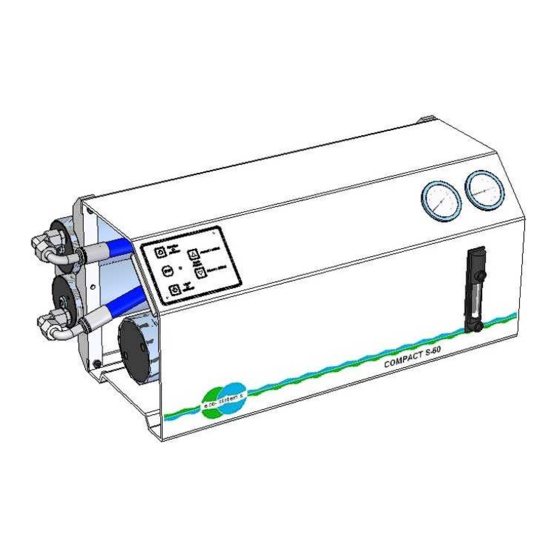
COMPACT S-60/90 12/24V DC
Version: 150720
Referencia: 45200012
Eco-Sistems Watermakers, S.L.
Oficina: C/ Horta nº 22 – Almacén: C/ Gran Vía Puig i Cadafalch nº 233
(08203)- Sabadell – Barcelona (Spain)
Tel: 34.93.710.89.50 – Fax: 34.93.712.23.55
E-mail:
info@eco-sistems.com
Web:
www.eco-sistems.com
Advertisement
Table of Contents

Related Manuals for ECO SISTEMS Water-pro Compact S-90 12V

Summary of Contents for ECO SISTEMS Water-pro Compact S-90 12V
- Page 1 ECO-SISTEMS WATERMAKERS S.L. Owner’s Manual WATER-PRO SERIES COMPACT S-60/90 12/24V DC Version: 150720 Referencia: 45200012 Eco-Sistems Watermakers, S.L. Oficina: C/ Horta nº 22 – Almacén: C/ Gran Vía Puig i Cadafalch nº 233 (08203)- Sabadell – Barcelona (Spain) Tel: 34.93.710.89.50 –...
- Page 2 WATER-PRO COMPACT S-60 12/24V DC POWER BOX COMPACT-ASSY S-60 12/24 V DC LOW PRESSURE FILTER SET FEEDING-ASSY FILTER WRENCH S-60 12/24 V DC CONNECTOR 8TUBE X 1/4 BSP PLASTIC TUBE 8X6 BLUE 2-ADAPTER 1/2 BSP X 1/2 BARB PVC ADAPTER 3/4 BSP X 3/4 BARB PVC HOSE 1/2 BLUE 8 -HOSE CLAMP 12/22...
- Page 3 WATER-PRO COMPACT S-90 12/24V DC POWER BOX COMPACT-ASSY S-90 12/24 V DC LOW PRESSURE FILTER SET FILTER WRENCH FEEDING-ASSY S-90 12/24 V DC CONNECTOR 8TUBE X 1/4 BSP PLASTIC TUBE 8X6 BLUE 2-ADAPTER 1/2 BSP X 1/2 BARB PVC ADAPTER 3/4 BSP X 3/4 BARB PVC HOSE 1/2 BLUE 8 -HOSE CLAMP 12/22...
-
Page 4: Table Of Contents
- II.2. Shutting down for short periods of time. - II.3. Shutting down for long periods of time. CHAPTER III: • Parts listing and exploded view of the ST-15/CERAMIC Eco-sistems pump. - ST-15/CERAMIC Eco-Sistems pump elements CHAPTER IV: • Filter and Membrane Replacement. IV.1. Changing the filters. - Page 5 CHAPTER I INTALLATION, OPERATION AND MAINTENANCE...
- Page 6 LAVADO PRODUCCION LAVA PR ODUCTION FRESH FLUSH FRESH FLUSH STOP eco - sistems 12/24 V DC WATER-PRO COMPACT S-60/90 12/24 V DC...
-
Page 7: Chapter I
Chapter I Page 2 SYSTEM COMPONENTS 1. - Seacock valve to uptake the sea water. 2. - Check Valve. 3. - Protection pre-filter (Washable mesh filter). 4. - Low pressure booster pump 12/24V DC motor. 5. - Low Pressure Gauge. 6. -
Page 8: Installation
Chapter I Page 3 I.1. Installation. (See diagram Chapter I Pages 1 and 2) To install the unit the following inlet and outlet connections are needed: • Sea cock valve (1) with a minimum nominal pitch of 3/4” Gas for sea water intake, which should be installed as low as possible at the bottom of the hull in order to prevent possible cavitation problems due to air suction. - Page 9 Chapter I Page 4 I.2.Hydraulic connections. The connection between the various components will be made with the tubes supplied with the unit, as shown in the diagram in Chapter I Pages 1 and 2. • The two suction connections between the sea cock valve (1) and the check valve (2) will be made using the transparent Ø20 tube.
-
Page 10: Electronic Control Panel
Chapter I Page 5 I.3. Electronic Control Panel The electronic Control Panel (21), shown in the diagram of Page 1 Chapter I consists of two push buttons that allow for an increase or decrease in the Motor pump’s feeding speed (4) and three buttons equipped with light indicators that allow for a complete control of the system. - Page 11 Chapter I Page 6 REMOTE CONTROL PANEL CONTROL PANEL REMOTO ETAPA POTENCIA BACK SIDE (REGULATED 18 BAR) 4 3 2 1 PRESSURE SWICH N/C CONNECTOR (red) RJ-45 (ETHERNET) ALARMS 12/24 V DC ELECTROVALVE 12 ó 24V DC ACCORDING THE POWER SUPPLY S-60-C 25A.
-
Page 12: Electrical Connection
Chapter I Page 7 I.4. Electrical Connection. The system comes equipped with an electrical motor for the low-pressure pump 12/24V DC at 2000 rpm. It must be connected using the moisture shielded cable with a cross- section appropriate for the distance between the batteries and the motor. The recommended cables are the following ones: Model / Power nominal motor 60 Litters/550watios... - Page 13 Chapter I Page 8 ELECTRONIC 12/24 V DC CONTROL PANEL ADJUSTS (Recommended for experts only) FLUSH WATER FLOW ADJUST • Turn on the system while pressing the LAVADO/FRESH FLUSH button, the blue LED on the control unit will turn on. •...
- Page 14 Chapter I Page 9 ALARMS AND PROTECTION OF THE 12/24 V DC POWER BOX • There is a 3 Amp fuse, it can be found under the cover. • If the aluminum radiator exceeds a temperature of 65 degrees the red led located in the control panel will flash, then the power box will cut the power supplied to the motor pump and the power box.
-
Page 15: First Start Up
Chapter I Page 10 I.5. First Start Up. • Check if all connections have been properly made and if the voltage at the terminals is the appropriate one. • Check if the Sea Cock Valve (1) is opened. In case the optional valve (11) is not installed, its connection to the main tank will be removed. -
Page 16: Start-Up
Chapter I Page 11 I.6. Start-up • Before starting up the system make sure the sea cock valve (1) is completely open • Ensure there is pressure in the boat’s fresh water circuit. • Start the motor and check that the pressure in the low pressure gauge (5) lies between approximately 10 and 12 kg/cm , and does not exceed 15 kg/cm under... -
Page 17: Maintenance Of The Unit
Chapter I Page 12 • The high pressure will fall to around 20-30 kg/cm2. This significant decrease in high pressure means that the seawater contained in the membranes has been cleaned out and replaced by fresh water. Changing the salinity and pH of the water in the membrane prevents the biological fouling from latching on to the membrane for a maximum period of 90 days. -
Page 18: Storage And Cleaning
CHAPTER II STORAGE AND CLEANING. - Page 19 VERY IMPORTANT REMEMBER THAT FOR A LONGER LIFE OF YOUR MEMBRANE, YOU MUST CLEAN THE SYSTEM WITH FRESH WATER AFTER EVERY USE.
-
Page 20: Ii.1 Storage Precautions
Chapter II Page 1 II.1 Storage precautions PREVENTION OF CHEMICAL ATTACKS ON THE SYSTEM Do not use for storage purposes, or expose the unit to, hydrogen peroxide, chloramine, chloramine-T, N-chloroisocyanide, chlorine dioxide, hypochlorite, chlorine, iodine, bromine, bromide, phenolic disinfectants or any other chemical element. The use of unauthorized chemical elements, or the abuse of authorized ones, will invalidate any warranty. -
Page 21: Ii.2. Shutting Down For Short Periods Of Time
Chapter II Page 2 II.2. Shutting down for short periods of time. Shutting down for a short period of time means when the unit will not be used for between one day and three months. An excellent and inexpensive way to protect the system and the membrane is the described in the Switching off the unit section which guarantees protection against the biological fouling in the membranes. - Page 22 Chapter II Page 3 3. Dissolve of 30/40 grams of chemical protector (sodium metabisulfite) with the 5 liters of water you set aside in a different container and suction this solution using the auxiliary valve (22). 4. Close the sea cock valve (1) and start up the system by pressing PRODUCCION, and press STOP just before the chemical protector and water solution from the tank runs out.
-
Page 23: Parts Listing And Exploded View Of The St-15/Ceramic
CHAPTER III PARTS LISTING AND EXPLODED VIEW OF THE ST-15/CERAMIC ECO-SISTEMS PUMP. - Page 24 Chapter III Page 1 Eco-Sistems ST-15/CERAMIC PUMP ELEMENTS Part Breaking- Description Quantity Number Up number 44015010 Distributor body ST-15 44015020 Superior plate 44015030 Central frame ST-15 44015040 Control Slider base 44015050 Lower plate 44015060 External cylinder liner 44015070 Intermediate small cap ST-15 (E)
- Page 25 Chapter III Page 2 Part Breaking- Description Quantity Number Up number 43823060 Grower ring Ø6 A4 43830606 Allen spike M6x6 A4 43850510 Cylindrical fastener DIN-7 A4 Ø5X10 43910540 O-ring Ø5x2 43911041 O-ring Ø10.5x2 43911240 O-ring Ø12x2 43911340 O-ring Ø13x2 43911540 O-ring Ø15x2 43912235 O-ring Ø21.95x1.78...
-
Page 26: Eco-Sistems Pump
ECO-SISTEMS PUMP ST-15... -
Page 27: Filter And Membrane Replacement
CHAPTER IV FILTERS AND MEMBRANE REPLACEMENT... -
Page 28: Iv.1. Changing The Filters
Chapter IV Page 1 IV.1. Changing the filters. When changing the filter cartridge make sure the sea cock valve is closed, before unscrewing the bowl filter that enables to remove the old cartridge and replace it with a new one which has the same specifications: 9 ¾ long, 5 micron calibrated filter. We do not recommend another type of cartridge;... - Page 29 Chapter IV Page 2 • Check that the membrane permeation tube fits properly into the O-rings inside the sealing caps (3). • Place the membrane and screw the end caps previously removed, with the pivot wrench. • Repeat the operation with the other vessels. •...
- Page 30 SALIDA /OUTLET ENTRADA / INLET SALIDA /OUTLET ENTRADA / INLET ENTRADA / INLET SALIDA /OUTLET SALIDA /OUTLET ENTRADA / INLET SALIDA /OUTLET ENTRADA / INLET 90 l/h 60 l/h 60 l/h SEAL...
Need help?
Do you have a question about the Water-pro Compact S-90 12V and is the answer not in the manual?
Questions and answers