Advertisement
Quick Links
Montageanleitung
Reifendruckkontrollsystem
Installation Instructions
Tire Pressure Monitoring System
Instructions de montage
Système de contrôle de pression-
des pneumatiques
Monteringsanvisning
Däcktrycksövervakningssystem
Montagehandleiding
Bandenspanningscontrolesysteem
Instrucciones de montaje
Sistema de regulación de la
presión de los neumáticos
Instruzioni di montaggio
Sistema di controllo pressione
pneumatici
Asennusohje
Paineenvalvontajärjestelmä
TC-400
Advertisement

Related Manuals for Hella TC-400

Summary of Contents for Hella TC-400
- Page 1 Tire Pressure Monitoring System Instructions de montage Système de contrôle de pression- des pneumatiques Monteringsanvisning Däcktrycksövervakningssystem Montagehandleiding Bandenspanningscontrolesysteem Instrucciones de montaje Sistema de regulación de la presión de los neumáticos Instruzioni di montaggio Sistema di controllo pressione pneumatici Asennusohje Paineenvalvontajärjestelmä TC-400...
- Page 2 D D E E U U T T S S C C H H Technische Änderungen vorbehalten E E N N G G L L I I S S H H Subject to alteration without notice F F R R A A N N Ç Ç A A I I S S Sous réserve de modifications techniques S S V V E E N N S S K K A A Med föfbehåll för tekniska förändringar...
- Page 3 Vorsichtsmaßnahmen Das Reifendruckkontrollsystem nur von Fachleuten einbauen lassen. Funkcode und alle Systeme in einem tragbaren Speichermedium festhalten. Vor dem Ausführen von Arbeiten an der Elektroanlage des Autos die negative Batterieklemme lösen. Zum Schutz des Kabelsatzes und der Antenne vor Beschädigung darauf achten, dass Kontakt mit scharfen Kanten vermieden wird.
- Page 4 L L i i e e f f e e r r u u m m f f a a n n g g...
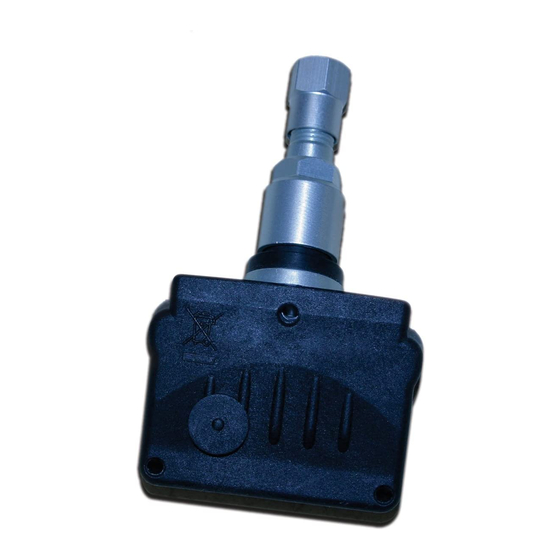
- Page 5 L L i i e e f f e e r r u u m m f f a a n n g g Radsensoren 4 Stück (A), Receiver (B), flexible Antenne (C), LCD-Display (D), Schraube 5 x 3 mm (E), Schraube 12 x 4 mm (F), Stromkabel mit Sicherung (G), Halterung für das Display (H), doppel- seitiges Tapepad 45 x 19 mm (I), 4-Pin-Stecker (J), Kabelbinder 4,8 x 432 mm (K), Kabelbinder 4,8 x 432 mm (L), doppelseitiges Tapepad 45 x 19 mm (M), Montage- und Bedienungsanleitung (N).
- Page 6 1 1 1 1...
- Page 7 1 1 2 2...
- Page 8 1 1 3 3 0-3 mm...
- Page 9 1 1 4 4...
- Page 10 For use in all EU member states For use in all EU member states A10-560012A 086000202 LF A10-560012A 086000202 RF LF = LEFT FRONT RF = RIGHT FRONT 1 1 5 5 For use in all EU member states For use in all EU member states A10-560012A 086000202 LR A10-560012A...
- Page 11 1 1 6 6...
- Page 12 1 1 7 7...
- Page 13 1 1 8 8 160km/h Bar/psi/kPa 155/70R13 2,3/33/230 2,5/36/250 1,8/26/180 2,5/36/250 165/65R13 2,1/30/210 2,5/36/250 1,8/26/180 2,5/36/250 165/60R14 2,3/33/230 2,5/36/250 1,8/26/180 2,5/36/250...
- Page 14 1 1 9 9...
- Page 15 2 2 0 0...
- Page 16 2 2 1 1 CHECK SET UP CHECK SET UP...
- Page 17 2 2 2 2...
- Page 18 2 2 3 3...
- Page 19 D D E E U U T T S S C C H H Bedienungsanleitung Seite 25 - 45 E E N N G G L L I I S S H H User handbook Page 46 - 66 F F R R A A N N Ç Ç A A I I S S Manuel utilisateur Page 67 - 87 S S V V E E N N S S K K A A Bruksanvisning sidan 88–108...
-
Page 20: Diagnostic Check
DIAGNOSTIC CHECK Press and hold Check button on display. Turn on ignition Release Check button when display shows: The system will show interference diagnostics thus advising Receiver location suitability. 3 rows of bars means interference is non existent or minimal. Receiver location is optimal. 4 4 6 6 2 rows of bars means interference is acceptable. - Page 21 PRE-PROGRAMMED WHEEL LOCATIONS All sensors are pre-programmed at the factory for a specific wheel location, which is used for the first install on your vehicle. Positions are indicated on a label attached to the front of the sensor body. Left Front Right Front Right Rear Left Rear...
- Page 22 (RE) PROGRAMMING WHEEL LOCATIONS Press and hold Check button on display. Turn on ignition Release Check button when display shows Ln5 To program Spare Wheel sensor Proceed to step 4 To disregard Spare Wheel sensor Proceed to step 5 Deflate Spare Tire by more than 3 PSI (0,2 BAR). The Spare Wheel sensor is programmed when a confirmation beep tone sounds.
- Page 23 (RE) PROGRAMMING WHEEL LOCATIONS Deflate Right Rear tire by more than 3 PSI (0,2 BAR). The RR sensor is programmed when a confirmation beep tone sounds. Display shows 004 Deflate Left Rear tire by more than 3 PSI (0,2 BAR). The LR sensor is programmed when a confirmation beep tone sounds.
- Page 24 SET STANDARD PRESSURE 160km/h & WARNING LEVELS Bar/psi/kPa 155/70R13 2,3/33/230 2,5/36/250 1,8/26/180 2,5/36/250 Inflate all tires to the prescribed pressures as 165/65R13 2,1/30/210 2,5/36/250 1,8/26/180 2,5/36/250 165/60R14 2,3/33/230 2,5/36/250 1,8/26/180 2,5/36/250 indicated in vehicle service manual or on the pressure placard attached to vehicle. Press and hold Check button on display.
- Page 25 SET WARNING LEVELS Your TPM system is equipped with a 2-stage warning system: 1. First warning is given for pressure loss situations of 25% or more. 2. Second - more firm - alarm is given for pressure loss of 50% or more. Note: the manufacturer strongly recommends maintaining default system settings to avoid false alarms triggered by temperature/pressure variations.
- Page 26 SET STANDARD PRESSURE & WARNING LEVELS Confirm setting by pushing Check button for 3 seconds, confirmation beep tone sounds and 3 Sec. display shows 50. Press Check button to adjust second stage warning level between 50% and 80%. Note: this means pressure loss varying between 20% and 50%.
- Page 27 SYSTEM SELF-CHECK & WHEEL LOCATION Turn on ignition. The system performs a self check and receives latest updated information of all wheel locations. If all conditions are OK, then the display will dim after 1 minute. 5 5 3 3 CHECK WHEEL LOCATION When Check button is pressed again within 1 minute, display will show Left Front tire condition.
- Page 28 CHECK WHEEL LOCATION When Check button is pressed again within 1 minute, display will show Right Rear tire condition. Display will dim after 1 minute. When Check button is pressed again within 1 minute, display will show Left Rear tire condition. Display will dim after 1 minute or proceed to Step 8a, 8b or 8c Without Spare Wheel...
- Page 29 CHECK WHEEL LOCATION With Spare Wheel When Check button is pressed again within 1 minute, display will exit set up mode. For 6 Wheel Vehicles When Check button is pressed again within 1 minute, display will show Left Outer Rear tire condition. Display will dim after 1 minute or proceed to Step 10 For 6 Wheel Vehicles 5 5 5 5...
- Page 30 ALERT / ALARM CONDITIONS Normal situation All tire conditions are OK First stage warning (US: Yellow/ EU: Orange) Low pressure warning Second stage alert (US: Yellow/ EU: Red) Low pressure alert 5 5 6 6 Fast leakage alert (US: Yellow/ EU: Red) Quick pressure loss alert of more than 3PSI (0.2 Bar) within 1 minute High Pressure alert...
- Page 31 ALERT / ALARM CONDITIONS Alarm or alert situation (Yellow/ Orange or Red) When the system issues any type of alarm or alert, a buzzer is activated. Press Check button to temporarily disable the buzzer sound. Note: the buzzer will repeat and sound again for the duration that the problem has not been fixed.
- Page 32 USING SPARE TIRE If a Pressure Alert is given and the tire needs to be replaced, it is possible to: 1. temporarily disable the sensor if not fitted with a sensor => Proceed to Step 8 2. change positions on screen in case your spare tire is equipped with a sensor =>...
- Page 33 USING SPARE TIRE (e.g.) Left Front and Spare Wheel will light up sequentially. Press Check button to accept this change, (e.g.) Left Front replaces Spare Tire. A beep tone confirmation acknowledges the change. While pressure alert is active, press and hold Check button for 5 seconds until confirmation beep tone sounds.
- Page 34 USING SPARE TIRE Disabled (e.g.) Left Front wheel location lights up. Press Check button to accept => temporarily disabled (e.g.) left Front position is now reinstated and activated. A beep tone confirmation acknowledges the change. 6 6 0 0...
-
Page 35: System Configuration
SYSTEM CONFIGURATION Your TPM system uses default settings PSI and °Fahrenheit; you may change these settings to your personal preference using following procedure: Press and hold Check button on display. Turn on ignition. Release Check button when display shows PSI and °F (after 9 seconds) 6 6 1 1 Change system configuration by... - Page 36 SYSTEM CONFIGURATION Display shows for: Pressure KPa Temperature °F Display shows for: Pressure PSI Temperature °C Display shows for: Pressure PSI 6 6 2 2 Temperature °F Display shows for: Pressure Bar Temperature °C Confirm setting by pressing and holding Check button for 3 seconds, confirmation beep tone sounds.
- Page 37 CHECK PRESET PRESSURE Press the Set button for displaying the preset pressure. Note: this function works after the system has dis- played all the tire conditions. The display shows the Preset pressure of the front wheels for 5 seconds and moves to step 3 The display shows the Preset pressure of the Rear wheels and it will exit after 5 seconds.
-
Page 38: Change Background Color
CHANGE BACKGROUND COLOR Press and hold the Set-up button. Release the button after 3 second after hearing the first confirmation beep. The display shows Co.1 ~ Co.7 Press on the Set-up button to scroll through: - Co.1 = Blue - Co.2 = Red - Co.3 = Green - Co.4 = Orange 6 6 4 4... - Page 39 CHANGE THE WARNING COLOR SETTINGS The systems configuration is set to the US warning strategy and this way the system will give only Yellow warnings. To adjust the setting to the European warning settings Orange and Red proceed with the following setting change. Press and hold the Set-up button.
- Page 40 Disclaimer TPMS is designed to monitor tire pressure and temperature conditions and inform the driver. TPMS does not carry out corrective actions, it is the drivers own responsibility to carry out the corrective actions at the earliest possible stage! TPMS is unable to detect an instant tire burst or other defect timely and inform the driver in advance.
- Page 41 „In geval van vragen of montageproblemen verzoeken wij u contact met de HELLA- klantenservice, de groothandel of uw dealer op te nemen.“ En caso de dudas o problemas de montaje, por favor, llame al Servicio postventa de Hella o al mayorista, o bien diríjase a su taller.
- Page 42 Hella KGaA Hueck & Co., 59552 Lippstadt 460 940 - 00 10/06 www.hella.com Printed in Germany...
Need help?
Do you have a question about the TC-400 and is the answer not in the manual?
Questions and answers