Table of Contents
Advertisement
Quick Links
Advertisement
Table of Contents

Summary of Contents for Roper Scientific Photometrics SenSys
- Page 1 Artisan Technology Group is your source for quality new and certified-used/pre-owned equipment SERVICE CENTER REPAIRS WE BUY USED EQUIPMENT • FAST SHIPPING AND DELIVERY Experienced engineers and technicians on staff Sell your excess, underutilized, and idle used equipment at our full-service, in-house repair center We also offer credit for buy-backs and trade-ins •...
- Page 2 Artisan Technology Group - Quality Instrumentation ... Guaranteed | (888) 88-SOURCE | www.artisantg.com...
- Page 3 PPD is a trademark and Metachrome, PVCAM, and SenSys are registered trademarks of Photometrics Ltd. RS Image is a trademark and Photometrics is a registered trademark of Roper Scientific, Inc. Windows and Windows NT are registered trademarks of Microsoft Corporation in the United States and/or other countries.
- Page 4 Roper Scientific warrants this product against substantial defects in materials and / or workmanship for a period of up to one (1) year after shipment. During this period, Roper Scientific will repair the product or, at its sole option, repair or replace any defective part without charge to you. You must deliver the entire product to the Roper Scientific factory or, at our option, to a factory-authorized service center.
- Page 5 (1) year limited warranty and/or any other warranty, expressed or implied. 3. All warranty service must be made by the Roper Scientific factory or, at our option, an authorized service center. 4. Before products or parts can be returned for service you must contact the Roper Scientific factory and receive a return authorization number (RMA).
- Page 6 In no event shall Roper Scientific’s liability exceed the cost of the repair or replacement of the defective product or part.
- Page 7 Declaration of Conformity Roper Scientific, Inc. declares that the equipment described in this document is in conformance with the requirements of the European Council Directives, listed below: 89/336/EEC EMC Directive 93/68/EEC EMC Directive 73/23/EEC Low Voltage Directive on the approximation of the laws of Member States relating to Electromagnetic Compatibility and Product Safety.
-
Page 8: Table Of Contents
Optional System Hardware....................1 About this Manual ........................2 Environmental Requirements ....................2 Storage Requirements.......................2 Precautions..........................2 Repairs............................3 Cleaning .............................3 Roper Scientific Customer Service..................3 Chapter 2. System Installation Introduction ..........................5 Software Compatibility Requirements...................5 Host Computer Requirements ....................5 Multiple Cameras........................6 Software Installation.........................6 Connecting Mount Adapters, Tripod Mounts, and Other Instruments ......7 C-Mount Adapter ......................7... - Page 9 Lenses ............................18 Tripod Camera Stand ......................18 Chapter 4. Troubleshooting System Does Not Boot Normally..................19 New Hardware Found Dialog Box Does Not Appear (Windows 95/98/2000/ME/XP) ..20 Green LED Does Not Illuminate...................20 Spots in Image .........................20 Image is Smeared or Camera Will Not Reach Saturation..........20 Images Not Displayed Properly....................20 Camera Does Not Respond to Light..................21 Camera Shutter Needs Replacing..................21...
-
Page 10: Chapter 1. Introduction
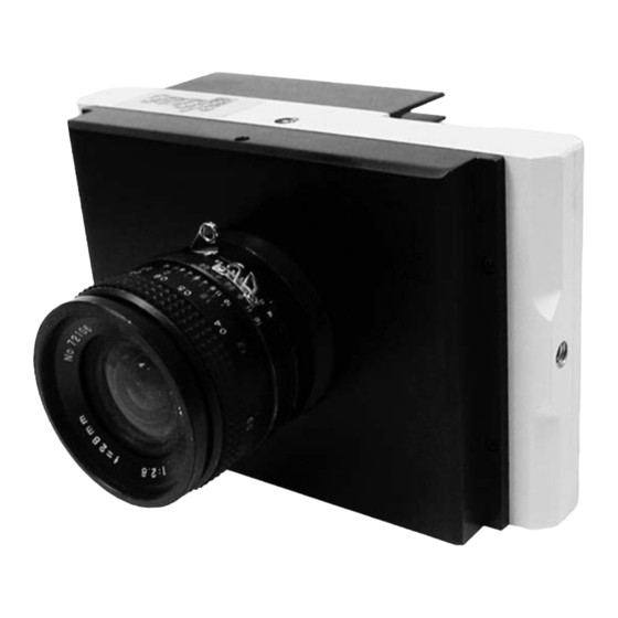
Introduction Chapter 1. SenSys ® is an air-cooled camera system with the ability to acquire low-light images by integrating (exposing) over long periods of time. The imager in the camera is a scientific-grade charge-coupled device (CCD). SenSys System All SenSys systems consist of standard hardware and software as well as the appropriate interface hardware (discussed in the Installation Guide) for your Components computer system. -
Page 11: About This Manual
About this The SenSys User Manual is divided into five chapters. It is suggested that you read the entire manual before operating the camera to ensure proper usage. The Manual chapters that follow this introduction are: • System Installation — Instructions for installing the camera system’s hardware and software. -
Page 12: Repairs
Clean exterior surfaces of the camera system with a dry, lint-free cloth. To remove stains, contact Roper Scientific Customer Service. Roper Scientific If you have any questions about your camera system, contact Roper Scientific Customer Service. When you call, please have your Roper Scientific job number Customer Service or equipment serial numbers available. - Page 13 This page intentionally left blank. SenSys User Manual Artisan Technology Group - Quality Instrumentation ... Guaranteed | (888) 88-SOURCE | www.artisantg.com...
-
Page 14: Chapter 2. System Installation
Keep all the original packing materials so you can safely ship the SenSys system to another location or return it for service if necessary. If you have any difficulty with any step of the instructions, call Roper Scientific Customer Service. -
Page 15: Multiple Cameras
If you are a Mac ® user, the host computer for your SenSys camera must have the following: • Macintosh ® OS 8.X, 9.X, or OS X • 64 MB RAM (or greater) • CD-ROM drive • At least one unused PCI card slot •... -
Page 16: Connecting Mount Adapters, Tripod Mounts, And Other Instruments
Connecting The camera is shipped with a removable F- or C-mount adapter attached. If applicable, change the mount adapter or attach a compatible lens. For Mount Adapters, information on changing the mount adapter, installing a compatible lens, or Tripod Mounts, installing a standard tripod camera stand, see below. -
Page 17: F-Mount Adapter
F-Mount Adapter The F-mount adapter is a standard Nikon bayonet mount with a standard F- mount flange focal distance and additional travel distance to allow parfocal adjustment with a variety of instruments. For specifications, see F-Mount Adapter on page 29. F-mount Assembly To install the F-mount adapter (if not pre-installed): 1. -
Page 18: Tripod Camera Stand
Tripod Camera Stand The SenSys camera has four mounting holes that are tapped for a standard tripod mounting bolt. Camera with Tripod Camera Stand To mount the SenSys camera on a tripod camera stand: 1. Loosen the tripod mount locknut so that the maximum length of the tripod mounting bolt is exposed. -
Page 19: Connecting The Data Cable
Connecting the The Data cable connects your SenSys camera to the PCI card installed in your computer. Data Cable Data Cable To connect your SenSys camera: 1. Connect either end of the Data cable to the Data port on the back of the camera (see the figure below). -
Page 20: Connecting The Power Brick
Connecting the The power brick is a switched supply that is shipped with a power cord. Power Brick Caution: Connecting or removing a live power cable to or from the SenSys camera can damage the camera's electronic components. Do not attach or remove any cables while the power brick is switched on (On = |, Off = 0) and plugged into an electrical outlet. -
Page 21: Focusing Your Camera
Focusing Your After you have finished system installation and have started the application software, you can focus the camera for the best image. Camera C-Mount Assembly To focus the camera: 1. If needed, back out the setscrews until you can freely rotate the C-mount adapter. -
Page 22: Chapter 3. Component Descriptions
Component Descriptions Chapter 3. The SenSys camera consists of the camera body and the shutter cover. The camera body houses the CCD, CCD cooling system, and camera electronics. All of the components inside the camera body are sensitive electronic components and are not user accessible. -
Page 23: Window
Window The SenSys camera has one window in the optical path. The CCD does not have a window. Compared to a multiple-window design, a single window reduces the chance of image degradation due to multiple reflections, stray light, and interference patterns. The standard Photometrics window is made of fused silica (quartz) with a broadband antireflective coating. -
Page 24: Electronics
Electronics The CCD produces an analog signal. The camera electronics convert the analog signal into a digital signal, data that can be received by the host computer. Several factors influence what portion of the analog signal translates into digital data. One factor is the noise in the camera system. The system noise includes the thermal noise produced by the camera components and the read noise determined in part by how far the analog signal must travel. -
Page 25: Power Port
If the ambient temperature is between 0°C and 40°C, the CCD will usually reach operating temperature within 20-40 seconds. If operating temperature is not reached after approximately one minute, call Roper Scientific Customer Service. SenSys User Manual Artisan Technology Group - Quality Instrumentation ... Guaranteed | (888) 88-SOURCE | www.artisantg.com... -
Page 26: Power Brick
Power Brick The power brick is a switched, multiple-output-voltage supply with a detachable power cord. The camera system is powered on (|) and off (0) by a switch on the supply. More detailed specifications are available in Chapter 5. Specifications. Caution: Connecting or removing a live power cable can damage the camera's electronic components. -
Page 27: Lenses
The C-mount lens is a standard threaded video mount lens. Tripod Camera The camera has four tripod camera stand mounting holes (0.25”-20 UNC-2B with a 1/4” depth). A tripod camera stand is available through Roper Scientific. Stand SenSys User Manual... -
Page 28: System Does Not Boot Normally
Troubleshooting Chapter 4. If you have any difficulty while troubleshooting, or do not see your camera system’s symptoms listed here, contact Roper Scientific Customer Service. The following issues have corresponding troubleshooting sections in this chapter. System Does Not Boot Normally... -
Page 29: Green Led Does Not Illuminate
Allow approximately one minute for the camera to reach operating temperature and the green LED to come on. If the green LED does not illuminate, there may Not Illuminate be a problem with the camera's cooling system. Contact Roper Scientific Customer Service. Spots in Image... -
Page 30: Camera Does Not Respond To Light
2. As the camera is powering up: • If you hear 2 clicks separated by 1 second (shutter opening then closing), the shutter is working. Call Roper Scientific Customer Service for further instructions. • If you do not hear any clicks, hear 1 click, or more than 2 clicks, check the voltage between I/O port pins 3 and 9 while you are powering up the camera. - Page 31 2. Using a #1 Phillips screwdriver, remove the two #4-40 pan head Phillips screws that attach the shutter board. 3. Pull the shutter board straight up until it is unplugged from the main board. Then unplug the shutter power connector from the shutter board. 4.
-
Page 32: Camera Does Not Focus
See the instructions for focusing the camera in Focusing Your Camera on page 12. PVCAM Error If a PVCAM error message appears, note the message’s number code and contact Roper Scientific Customer Service. Message Appears Lengthy Pauses If you notice lengthy pauses marked by a lot of disk activity while imaging: During Imaging •... - Page 33 This page intentionally left blank SenSys User Manual Artisan Technology Group - Quality Instrumentation ... Guaranteed | (888) 88-SOURCE | www.artisantg.com...
-
Page 34: Chapter 5. Specifications
Specifications Chapter 5. Camera Weight: 3 lbs without lens or lens mount Width: 4.48 in (113.7 mm) Length: 7.15 in (181.6 mm) Thickness: 3.00 in (76.2 mm) for F-mount; 2.60 in (66.0 mm) for C-mount Window thickness: 1 mm Distance from top of shutter cover to CCD image plane: F-mount Distance C-mount Distance 0401E, 1602E, 3200E, and 3200ME... -
Page 35: C-Mount Camera
C-Mount Camera 2.60 in (66.0 mm) 7.15 in (181.6 mm) C-mount Camera Side View 2.60 in (66.0 mm) 4.48 in (113.8 mm) C-mount Camera Top View SenSys User Manual Artisan Technology Group - Quality Instrumentation ... Guaranteed | (888) 88-SOURCE | www.artisantg.com... -
Page 36: F-Mount Camera
F-Mount Camera 3.00 in (76.2 mm) 7.15 in (181.6 mm) F-mount Camera Side View 3.00 in (76.2 mm) 4.48 in (113.8 mm) F-mount Camera Top View Chapter 5. Specifications Artisan Technology Group - Quality Instrumentation ... Guaranteed | (888) 88-SOURCE | www.artisantg.com... -
Page 37: C-Mount Adapter
C-Mount Adapter 1.60 in dia. (40.6 mm) 1.00-32 UN Thread Top View of C-mount 1.60 in dia. (40.6 mm) .26 in (6.6 mm) .96 in dia. Threads at (24.5 mm) 32 threads/inch 1.50 in dia. (38.1 mm) Side View of C-mount (unmounted) .63 in (16.0 mm) minimum .71 in (18.0 mm) maximum* Shutter Blades... -
Page 38: F-Mount Adapter
F-Mount Adapter 1.93 in dia. 2.50 in dia. (49.0 mm) (63.5 mm) Top View of F-mount .67 in (17.0 mm) 1.02 in (25.9 mm) 2.35 in dia. (59.7 mm) 2.50 in dia. (63.5 mm) Side View of F-mount (unmounted) 1.72 in (43.7 mm) minimum 1.82 in (46.2 mm) maximum* Threads at 32 threads/inch... -
Page 39: Power Brick
Power Brick 2.25 in (57.1 mm) 6.97 in (177.0 mm) 3.74 in (95.0 mm) The power brick is a +5V DC and ±15V DC supply with 100-240V AC input at 50-60 Hz. The maximum power output is 55 W. DC Voltage Maximum Current Draw 2.05 A during cooldown 700 mA after camera has reached regulated... -
Page 40: Input/Output Port Pinout
Input/Output Port The input/output port provides information about trigger function and shutter status. All inputs are pulled up to +5V DC through 10k ohm resistors and filtered Pinout with 2200pf ceramic capacitors. Outputs are driven by a 74F374 latch. The minimum trigger pulse width is 1.1 µsec (1100 nsec). -
Page 41: Power Port Pinout
7 TRIGGER INHIBIT INPUT This input inhibits all trigger signals. If the input is pulled low, trigger activity is disabled. By default, the input is pulled high so the trigger circuitry is enabled. (The inputs are internally pulled up, therefore it is recommended to drive them with an open collector driver.) 8 TRIGGER INVERT INPUT Active low. -
Page 42: Data Cable Pinout
Data Cable Pinout Data Cable Pinout Pin # Signal Name Pin # Signal Name Pin # Signal Name Ground VD5- Ground FEN+ VD4- Ground LEN+ VD3- Ground VD2- Ground VD11+ PIX+ VD10+ VD1- VD9+ VD0- VD8+ VD7+ VD6+ Ground Ground Ground VD5+ FEN-... -
Page 43: Ccd Orientation
CCD Orientation Parallel Camera Front View — KAF 0401E, KAF 1602E, KAF 3200E, and KAF 3200ME CCD Orientation Serial Camera Front View — KAF 1401E CCD Orientation SenSys User Manual Artisan Technology Group - Quality Instrumentation ... Guaranteed | (888) 88-SOURCE | www.artisantg.com... -
Page 44: Ccd Specifications
CCD Specifications KAF0401E H x V: 768 x 512 Pixel Size: 9µm x 9µm Gain Relative Typical Typical Maximum ADC Detection Mode Setting Gain Noise System Gain Signal High Signal to 26e - 160Ke - (binned full well*) ≈ ≈40e - /ADU Noise ≈1x High Dynamic... -
Page 45: Kaf1401E
CCD Specifications (continued) KAF1401E H x V: 1317 x 1035 Pixel Size: 6.8µm x 6.8µm Gain Relative Typical Typical Maximum ADC Detection Mode Setting Gain Noise System Gain Signal High Signal to 20e - ≈20e - /ADU 80Ke - (binned full well*) ≈... -
Page 46: Kaf1602E
CCD Specifications (continued) KAF1602E H x V: 1536 x 1024 Pixel Size: 9µm x 9µm Gain Relative Typical Typical Maximum ADC Detection Mode Setting Gain Noise System Gain Signal High Signal to 26e - ≈40e - /ADU 160Ke - (binned full well*) ≈... -
Page 47: Kaf3200E
CCD Specifications (continued) KAF3200E H x V: 2184 x 1472 Pixel Size: 6.8µm x 6.8µm Gain Relative Typical Typical Maximum ADC Detection Mode Setting Gain Noise System Gain Signal High Signal to 18e - ≈22e - /ADU 90Ke - (binned full well*) ≈... -
Page 48: Kaf3200Me
CCD Specifications (continued) KAF3200ME H x V: 2184 x 1472 Pixel Size: 6.8µm x 6.8µm Gain Relative Typical Typical Maximum ADC Detection Mode Setting Gain Noise System Gain Signal High Signal to 18e - ≈22e - /ADU 90Ke - (binned full well*) ≈... - Page 49 This page intentionally left blank. SenSys User Manual Artisan Technology Group - Quality Instrumentation ... Guaranteed | (888) 88-SOURCE | www.artisantg.com...
-
Page 50: Appendix A. Trigger Modes
Trigger Modes Appendix A Introduction SenSys offers several methods of integration with external trigger sources, such as delay generators or laser pretriggers. The camera has a 9-pin, D-subminiature connector on the back for trigger-in and various TTL input and output operations (see page 31 for the pinout specifications). - Page 51 This page intentionally left blank. SenSys User Manual Artisan Technology Group - Quality Instrumentation ... Guaranteed | (888) 88-SOURCE | www.artisantg.com...
-
Page 52: Index
Index Hardware specifications (cont.) C-mount adapter, 28 Analog signal, 15 C-mount camera, 26 Bulb mode, 41 Data cable pinout, 33 Camera F-mount adapter, 29 cleaning, 3 F-mount camera, 27 repairs, 3 Input/Output (I/O) port pinout, 31 CCD. See Charge-Coupled Device (CCD) power brick, 30 CCD chamber, description, 14 Power port pinout, 32... - Page 53 Trigger modes (cont.) Strobe, 41 Readout rate, 15 Trigger-First, 41 Repairs, 3 Trigger signal, synchronizing, 15 Shutter Trigger-First mode, 41 description, 14 Tripod camera stand, 9, 18 location, 13 Troubleshooting, 19 possible lens interference, 7 TTL I/O trigger port. See Input/Output (I/O) replacing, 21 trigger port Software compatibility requirements, 5...
- Page 54 33.160.86.07.09 email: mail@roperscientific.de fax: 81.43.274.8023 email: princeton.instruments@wanadoo.fr email: sales@roper.co.jp Roper Scientific – Arizona Roper Scientific – New Jersey 3440 East Britannia Drive 3660 Quakerbridge Road Tucson, Arizona 85706 Trenton, New Jersey 08619 tel: 800.874.9789 or 520.889.9933 tel: 800.874.9789 or 609.587.9797 fax: 520.295.0299...
- Page 55 Artisan Technology Group is your source for quality new and certified-used/pre-owned equipment SERVICE CENTER REPAIRS WE BUY USED EQUIPMENT • FAST SHIPPING AND DELIVERY Experienced engineers and technicians on staff Sell your excess, underutilized, and idle used equipment at our full-service, in-house repair center We also offer credit for buy-backs and trade-ins •...
Need help?
Do you have a question about the Photometrics SenSys and is the answer not in the manual?
Questions and answers