Advertisement
Advertisement

Summary of Contents for Global Automatics Premier-Slide 100
- Page 1 Technical Manual © Premier-Slide 100...
-
Page 2: Table Of Contents
Table of Contents Introduction Pages 3-4 Preparation of Doors Pages 5-6 Installation of the Track & Door Heights Page Installation of Floor Guides Page Hanging & Aligning Doors Pages 9-10 Assembly of the Belt Brackets Page 11 Control Unit /Battery Unit Overview Page 12 Types of Access Switch Page 13... -
Page 3: Introduction
This Manual contains all the information you require to install, maintain and service your Premier-slide 100 automatic sliding door operator. The Premier-Slide 100 automatic sliding door system has been designed to create a reliable sliding door system which is simple to install and which has an easy setup procedure. - Page 4 Main Features: Personalised Colour Logo Self diagnostic system Only 100mm in Height Full microprocessor control with smooth motor control using encoder technology. Easy to adjust wheel systems. “Creep Speed” input. Electromagnetic motor lock as standard Fast Installation – minimal tools required. Monitored battery backup with optional opening Programs Switch-able Motor direction Slim-line mode switch: available in Surface, flush fit and canopy mounting options.
-
Page 5: Preparation Of Doors
Preparation of doors The door operator kit is supplied with an aluminium adaptor rail which needs to be fitted in the top to the door leaf. This adaptor allows the “door hanging brackets” to be easily attached to the door leaf. This should be cut the full internal width of the door leaves. Sufficient fixings / re-enforcement must be installed to carry the weight of the door leaf. - Page 6 Once the adaptor rail has been installed on the door leaf, then the “Door Hanging” brackets can be fitted to the adaptor, using the M8 bolts fitted to the steel threaded fixing plates. The door hanging brackets have slots to allow the door distance from the frame, to be adjusted as necessary.
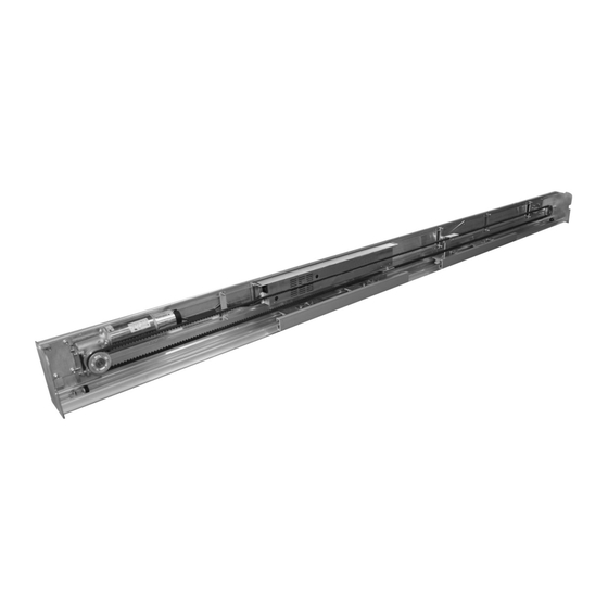
- Page 7 Installation of Track System - Always work in pairs. • The track system comprises an aluminium track section and a hinged / removable cover. (Please note: Sometimes there can be a slight bend to the length of long track extrusion but this is easily removed by fixing from one end and straightening it up as you go).
-
Page 8: Installation Of Floor Guides
Installation of Floor Guides The standard floor guide system available with the Premier-Slide uses a guide track installed into the bottom of the door rail and a floor mounted adjustable guide. The guide channel is simply cut to the inside dimension of the door leaf and attached using countersunk self tapping screws straight into the door rail. -
Page 9: Hanging & Aligning Doors
Hanging & Aligning Doors Procedure for wheel adjustment: When the Doors are hung, you need to adjust the anti-riser (Centre Wheel) up so that it touches the top of the track. This is to stop the doors from coming off of their track. Please do not have these tight against the track as they may cause friction problems. - Page 10 Aligning the doors Loosen the Door stops. Push the doors to the required maximum open position. Please remember that there must be a minimum of 25mm between the leading edge of the door (1) and the mullion of the fixed screen to avoid a finger trap.
- Page 11 Belt The Belt should be installed with the door in the closed position. Making sure the doors do not move; wrap the belt around the motor and Idler wheel. Measure and cut as required. The belt should now be clamped to the carriage assemblies and tensioned to allow the door to work properly. The Belt bracket is secured to the carriage assemblies via 2 x Bolts.
- Page 12 Control Unit The Premier-slide 100 Control unit is an “all in one” control system incorporating A Control system, Power supply unit, monitored battery backup and dedicated wiring system. The Mains Power is supplied via an IEC “Kettle” Plug in the L/H side of the Control Unit. Next to this on the L/H Side this is the motor connection plug.
- Page 13 Access Switch The Access Switch comes with 3 Meters of cable as standard, This can be extended as required up to 15 meters with screened cable. (Do not Disconnect the Access switch whilst the Power is on.) Surface Mounted Locate a suitable position for Access panel / switch and install using 4 x screws. If mounting to a hollow section such as aluminium frame mullion, you will need to drill a 20mm hole so the wiring can be concealed within the hollow chamber of the frame section.
-
Page 14: Customer Door Operating Modes
CUSTOMER DOOR MODES Automatic This is the Main mode for Customer Use. Activation Sensors or press pads work from both directions. Exit Only Only the Inner activation sensor works – Allows people to exit via the door. Enter Only Only the Outer activation sensor works – Allows people to enter via the door. Hold Open When set to this function, the door will stand in the open position until the mode is changed. -
Page 15: Using The Access Panel
USING THE ACCESS PANEL - CUSTOMER When the Access Switch is Inactive it will automatically lock to stop unauthorised usage. To gain access to the Customer menu where you can change the mode of the door you simply hold the Select button in for 2-3 seconds. -
Page 16: Door Start Up Procedure
DOOR START UP PROCEDURE When the doors are hung, the sensors fitted and wired you can now start the door up. The door has a learn cycle it goes through. With the mains on, • Turn on the Conrol unit. Please make sure the Area the door opens/closes and the sensor fields are clear from people and objects as they may affect the learn cycle. - Page 17 Access Panel – Installer Setup Mode ( 2x Down, 2x Up, Select) To gain Access to the installer’s mode, you need to press the down button twice, then the up button twice and press select. This will take you to the first screen of the Installers menu. From here you can navigate up or down through the Menu as detailed below.
- Page 18 INSTALLERS MENU EXPLAINATION Monitored Safety On This screen you can see the Safety sensors of your doors. This serves two purposes. 1) If the Writing is green it means that your sensors are not active. If any are in Red, this indicates that the particular Safety sensor is receiving any activation.
- Page 19 Closing Speed Group 1-5 - Single door settings 6-9 – Double door settings The Speed Group Combines the High speed, Braking Force, Braking Distance, Low Speed and Safety Speed into one convenient group. These groups have been assembled to allow a smooth operation of the sliding door.
- Page 20 Access Panel – Technicians Mode (3x up, 3x down, select) To gain Access to the Technicians mode, you need to press the up button three times and then the down button three times followed by select. This will take you to the first screen of the Technicians menu. From here you can navigate up or down through the Menu as detailed below.
- Page 21 Technicians Mode – Explanation TIP: When you have finished your adjustments, you can press the up and down arrows together at any time to short cut you straight back to the exit screen. Press select on the exit screen and you will exit engineer’s mode and return to the customer menu.
- Page 22 Holding force – Closed This is an adjustable force applied to the door when in the closed position. This force is only applicable if the Motor Lock is turned OFF. The door has little holding force. The door can be pulled manually and the “Push & Go” will activate after approx 20mm.
- Page 23 Battery mode This is a selectable option for the Type of operation you wish the door to do upon mains failure. Fail open – In the event of a mains power failure the door will sit in the open position until the mains is reinstated.
- Page 24 Service number Here you enter your service telephone Number. This is the number that is displayed on the screen when a fault is detected. Use the up and down arrow to run from 0 to 9 plus a space , when you get to the digit you need press the select button and it will move to the next character.
- Page 25 Monitored safety screen On this screen it gives you the details of your safety sensors (Threshold and side screen sensors) Each sensor will be in Green and will have a yes or No next to it. This Yes or No indicates if the Sensors are monitored or not. (Automatic detection upon installation of sensors) If any of the Sensors are activated, the Text turns to red.
- Page 28 Door Weight Below is an approximate Graph to help you calculate the door weight. Please bear in mind that this table is for guidance only, it assumes that the door is made of typical 3mm wall aluminium without a midrail. Wooden, steel and other types of door should be assessed individually. You will need to Times the Door Height by the Door width to get an overall area to use the table below.
- Page 29 Fault Finding Fault Finding is made easy on the Premier-slide 100 as it has a comprehensive diagnostic system. For all major faults the door will display an error on the screen. For sensors it will say “Sensor Failure”. You can then enter the technician’s mode and identify the exact sensor in the Fault Log or Information screen.
- Page 30 SHORT CIRCUIT...
- Page 31 Paint Care Although Powder coating is a long life finish of up to 25 Years, care should be taken when handling products that have been finished. Sharp edges can scratch and Pierce Powder coated surface. Powder coating should be cleaned down with warm water and a mild detergent. Do not use any strong cleaning chemicals as it may affect the paint.
-
Page 32: Technical Specification
Technical Specification Single Door Double Door Max Door Width 2000mm 3000mm Max Door Height 3000mm 3000mm Max Door Weight 120kgs(Guidance) 180kgs(Guidance) Mains Voltage 180v - 250 v ac Hold Open time 0 – 60 Sec Opening Speed Max 600mm / Sec Closing Speed Max 600mm / Sec Partial Opening...
Need help?
Do you have a question about the Premier-Slide 100 and is the answer not in the manual?
Questions and answers