Advertisement
Quick Links
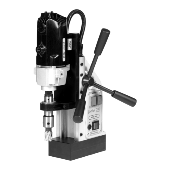
POWERBOR PB32 & PB32 COMBI
ELECTRO-MAGNETIC HOLE CUTTING SYSTEM
WARNING !
Read and understand this manual
and all instructions before operating
the machine.
Failure to follow all instructions may
result in electrical shock, damage
to the machine or even personal
injury.
The POWERBOR
INSTRUCTION MANUAL
©
range of machines are exclusively manufactured by
G&J Hall Ltd, Sheffield, England
Machine shown PB32
without safety guard for
clarity.
PB32 - Revised 120810
Advertisement

Subscribe to Our Youtube Channel
Summary of Contents for G&J Hall POWERBOR PB32
- Page 1 POWERBOR PB32 & PB32 COMBI ELECTRO-MAGNETIC HOLE CUTTING SYSTEM INSTRUCTION MANUAL WARNING ! Read and understand this manual and all instructions before operating the machine. Failure to follow all instructions may result in electrical shock, damage to the machine or even personal injury.
-
Page 2: Machine Specification
MACHINE SPECIFICATION PB32 Machine Height 300mm (slide in down position) Machine Width 90mm (without handles) Machine Depth 240mm Stroke 165mm Machine Weight 12.5Kg Rated Motor Power 720W Voltage 110V / 240V AC Rated Current 6.0A / 3.0A IP Rating IP20 Spindle Speed 550 min (no-load load speed will vary with cutter diameter) - Page 3 PB32 BASIC DIMENSIONS NOTES PB32 - Revised 120810...
- Page 4 INTENDED OF USE OF POWER TOOL This power tool is intended to be used for drilling holes with annular cutters, twist drills, counterbores, countersinks and step drills in an industrial environment. The PB32 COMBI also has variable speed and FWD/REV for tapping threaded holes. The machine is meant to be held onto a magnetisable surface using its electro-magnetic base.
-
Page 5: General Power Tool Safety
GENERAL POWER TOOL SAFETY WARNING: When using electrical power tools basic safety precautions should always be followed to reduce the risk of fire, electrical shock or personal injury. Please read the following carefully. Working Environment. Always keep the working area well lit and uncluttered. A poorly lit or untidy workspace can lead to accidents. - Page 6 ELECTRICAL SAFETYAlways carry the power tool properly with the carrying handles Earthing / Grounding. This power tool requires a ground or earth connection. The power tool must be plugged into an outlet properly installed and grounded or earthed in accordance with all local codes and regulations. Never remove or tamper with the ground or earth prong in any way.
- Page 7 PERSONAL SAFETYAlways carry the power tool properly with the carrying handles pro- Attention Always watch what you are doing and use common sense at all times when operating power tools. Do not use the power tool whilst tired, or under the influence of drugs, alcohol or medication.
- Page 8 MAGNETIC DRILL SAFETYAlways carry the power tool properly with the carrying han- Safety Strap The electro-magnet base on this power tool can release if there is a interruption in power supply or electrical malfunction. The safety strap provided should be used at all times to prevent the power tool from falling in the event of power failure or electrical malfunction, possibly causing injury.
-
Page 9: Warranty
TOOL USE AND CAREAlways carry the power tool properly with the carrying handles Always ensure the work piece is secure and stable before attempting to work on it. Do not force the tool, always use the correct type of cutting tool for your application and use it at the rate it was designed to work at. - Page 10 USING THE SAFETY STRAP carry A ratchet type safety strap is provided. The power tool has 2 x „D‟ loop rings to allow the hooks on the safety strap to be attached securely. RATCHET STRAP Always ensure the strap is correctly fitted and the machine is secure BEFORE starting the motor unit.
- Page 11 MOUNTING CUTTERS INTO THE ARBOR The holder for the cutting tool is known as the arbor. The arbor is designed to accept Powerbor 3/4” Weldon shank annular cutters. The Powerbor annular cutters normally have two flats disposed at 90°to each other. To mount the cutter.
- Page 12 REVERSING OF THE HANDLES The three handles (C) which raise and lower the drill unit are attached to the pinion shaft (D). These handles and the pinion shaft itself can be turned around so the handles can be used on each side of the machine.
- Page 13 MOTOR CONTROL PB32 The drill unit or “motor” of the PB32 is controlled by a twin push button switch at the top of the control panel. The green button is ON the red button is OFF. The green button is flush with the surrounding bezel. The red button is raised above the surrounding bezel.
- Page 14 MAGNET CONTROL PB32 COMBI The PB32 Combi Magnet Control switch (I) is positioned at the top of the PB32 Combi control panel. „O‟ indicates magnet OFF „I‟ indicates magnet ON. Ensure the magnet switch is OFF and the FWD/REV switch is in the OFF position before connecting the power supply.
- Page 15 USING THE DRILL WITH ANNULAR CUTTERS Insert the correct pilot pin for the cutter into the pilot pin hole through the shank of the cutter. Mount the cutter in the tool holder (arbor) of the machine as described in previous chapters, ensuring the cutter is secure and correctly fitted.
- Page 16 TAPPING — PB32 COMBI ONLY The PB32 Combi, in addition to drilling with annular cutters, is designed to allow the tapping of screw threads. The tapping capacity of the PB32 Combi is M6 to M12. This machine has variable speed and both forward and reverse spindle rotation. Magnetic based drills are normally used for cutting through holes with annular cutters, the tapping facility of this drill is for tapping through holes.
- Page 17 TAPPING — PB32 COMBI ONLY (Cont.) 2 - IN - 1 Drill Tap When using a 2 - IN - 1 Drill Tap, this type of tap is restricted to plate thicknesses of the diameter of the tapping size. ie: M12 = 12mm plate. This is due to the length of the plain portion of the shank after the threaded portion.
-
Page 18: Maintenance
MAINTENANCE To keep this machine in a safe working condition regular certain maintenance is required. The gib strip on the dovetail slide must be adjusted to eliminate any free play. The dovetail slides will need to be lubricated will oil periodically. The magnetic base should be inspected for damage on its magnetic surface or for any damage to the resin, any damage should be repaired before using the drill. - Page 19 PB32 WIRING DIAGRAMS PB32 - Revised 120810...
- Page 20 PB32 COMBI WIRING DIAGRAMS PB32 - Revised 120810...
- Page 21 PB32 STAND - PARTS DIAGRAM ITEM Part No. Description ITEM Part No. Description 18Y519 CABLE GLAND (CORD GRIP) 18Y138 MAIN BODY CASTING 18Y134 ELECTRO-MAGNET BASE 18X519/A CONDUIT GLAND 18Y180 CONDUIT LEAD 18X312 BRASS GUIDES (PAIR) 18Y181 MAINS CABLE 110V (2P+E) 18Y140 MACHINE RACK 18X503...
- Page 22 PB32 - Revised 120810...
- Page 23 PB32 MOTOR - PARTS DIAGRAM PB32 - Revised 120810...
- Page 24 PB32 - Revised 120810...
- Page 25 PB32 ARBOR ITEM Part No. Description 18Y130 ARBOR BODY (1/2" X 20 UN) 18X321 ARBOR SPRING 18X323 ARBOR PISTON 18X206 3/4" INTERNAL CIRCLIP 18X205 M8 x 8 SOCKET SCREW PB32 - Revised 120810...
- Page 26 PB32 SAFETY GUARD PB32 - Revised 120810...
Need help?
Do you have a question about the POWERBOR PB32 and is the answer not in the manual?
Questions and answers