
Related Manuals for Magtech LTM-300 Series


Summary of Contents for Magtech LTM-300 Series
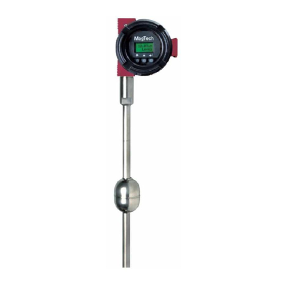
- Page 1 LTM-300 Series Magnetostrictive Level Transmitter Instruction & Operation Manual Jan 2009 3902 Magnolia Road Pearland. Texas. 77584 PH: 281/488-0788 FAX: 281/488-7080 : magtech@isemagtech.com www.isemagtech.com MAIL...
-
Page 2: Table Of Contents
Page 8.0 Standard ISE/MagTech Warranty......7 8.1 HART protocol Option Information ......8-18... -
Page 3: Section 1. Transmitter Overview Page
A Magtech assigns a unique serial number for each unit. The first two digits stilling well may be optionally used inside the tank or, in case of high indicate the month of production followed by two digits, indicating the temperatures;... -
Page 4: Section 2. Instrument Description Page
SECTION 2. Instrument Description Calibration routines are included in the software to scale the 4 and 20 mA points for any distance desired. Even reverse calibration is a simple task using the software routines. Reverse calibration is 2.0 Transmitter Detailed Description desirable if ullage instead of full level is required, or when the probe is installed with bottom mount head. -
Page 5: Level/ Temperature Transmitter
INTERCONNECT WIRING (CSA & FM) is rotated . If the head is loose, please notify the factory. The LTM-300 can be mounted to the side of a MagTech LG series level gage using a special mounting bracket and stainless steel hose clamps. When... -
Page 6: Recommended Wiring, Single Loop
3.2 Recommended Wiring, Ambient Temp. Range -20°C ... +40°C (-4°F ... 104°F) Single Loop Humidity Limits: SAMA PMC 31.1-5.2 Vibration Limits: SAMA PMC 31.1-5.3 RFI Limits: SAMA PMC 31.1-20 to 1000 MHz up to 30V/m 4.1 Transmitter Sensor Tube Material: 316ss standard, optional Hastalloy, Monel, Kynar coated Operating Temperature:... -
Page 7: On-Board Menus
5.1 LCD Menus For The LTM-300 Displays 1 2 3. 4 5 i n L e v e l Level Measurement Display - in inches 4 5 6 7 . 8 cm Level measurement Display - in centimeters 9 0 1 2 3. L e v e l Level Measurement Display - in millimeters 5 6. -
Page 8: Section 6. Troubleshooting And Maintenance
6.4 Start-Up for Gage-Mounted SECTION 6. Troubleshooting and Maintenance LTM Transmitters 6.0 Diagnostics are Via HART 6.1 Calibration Problems Gage and Transmitter Installation Visually inspect Mag-Gage and transmitter installation to If the transmitter does not appear to calibrate properly, or has an erratic insure transmitter is positioned with the 4 mA and 20 mA output, check the deadband of the sensor tube and ensure that the labels directly adjacent to the process connections. -
Page 9: Section 7. Field Insulation Of Gages With Transmitters Page
MagTech. Repairs and/or replacements MUST be done at the factory due to the custom “TUBE in TUBE: shall be at the sole discretion of MagTech based on the terms and design necessary for removal of the transmitter if needed. -
Page 10: Hart Protocol Option Information
If the user selects Basic setup from 8.1 HART Protocol Option Information the Device setup screen, the next screen has a mixture of further HART Communicator Overview menu selections and detailed information. This screen displays the name of the variable that is This section presents the major screen selections available to the controlling the output current (PV), user. - Page 11 If the user selects Operation Then the HART Communicator Status from the Diagnostics will report the results to the user screen, he is able to view all in sequence. In the example of the status bits indicating given here, the diagnostics has the health of the transmitter detected a problem with the Level operation.
- Page 12 The HART Communicator informs If the user wishes to specify a loop the user that the maintenance current other than 4mA or 20mA, flags have been reset when the he must select the option Other transmitter has replied to the and then press the ENTER key.
- Page 13 If it is desired to trim the digital level The transmitter, based on the value, he may select a single point data from the reference meter, zero trim or a full level trim that will calculate a new value for the requires the input of both the zero DAC zero calibration constant and level value and some other level...
- Page 14 The HART Communicator is now Zero Level Trim at the starting screen for the Zero Level Trim. Starting at the Calibration screen, select the Zero Level Trim procedure. This procedure trims the Level digital value measurement at the position that the user desires to be the zero Full Level Trim reference position.
- Page 15 The HART Communicator now Zero Temperature Trim requests that the level float be set to the desired level upper trim point. The second trim point can Starting at the Calibration screen, be any other level point but it is select the Zero Temper Trim recommended that this point be procedure.
- Page 16 The transmitter will take about The user is then notified that fifteen seconds to insure that the the loop may now be returned temperature signal has stabilized. to automatic control. After the Once the measurement is stable, user presses OK the HART the procedure will continue without Communicator returns to the user intervention.
- Page 17 Reranging the Transmitter The user is then notified that Setting the Measurement Value for 4mA and 20mA by Keypad the loop may now be returned to automatic control. After the If you desire to change the Level user presses OK the HART value at which the Current output Communicator returns to the is 4mA and 20mA when the Level...
- Page 18 The HART Communicator will On returning to the Keypad rerange display this screen reminding screen, the values shown for LRV the user that the loop should be and URV are the changes that the removed from automatic control user has made. The user should before proceeding.
- Page 19 The next screen gives the user If the user accepts the a choice to set the 4mA or 20mA measurement value as the values or to Exit the procedure. 20mA loop current point, the Here the user will select the 4mA HART Communicator issues the command changing the URV menu position.
- Page 20 @ 4mA. i.e. 4mA will be reported @ 5.0” if 5.0” is selected. The LTM-300 complies with the following standards: 3902 Magnolia Road, Pearland. Texas. 77584 IEC 60079-0, IEC60079-1 PH: 281/488-0788 FAX: 281/488-7080 EN 50014, EN 50018 : magtech@isemagtech.com www.isemagtech.com MAIL LTM300IOM Rev. 6.1...
Need help?
Do you have a question about the LTM-300 Series and is the answer not in the manual?
Questions and answers