Table of Contents
Advertisement
OPERATION MANUAL / SPARE PARTS LIST
PNEUMATIC
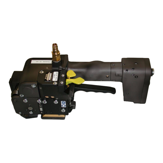
PLASTIC STRAPPING TOOL
MODEL P356
49.0374.01
CE Declaration of conformity
We declare that the machine P356
is in conformity with the following standard or
standardised documents:
98/37/EEC
FROMM Holding AG
Hinterbergstrasse 26
CH - 6330 Cham
14.05.2004
R.Fromm
Director
Advertisement
Table of Contents

Summary of Contents for Fromm P356
- Page 1 OPERATION MANUAL / SPARE PARTS LIST PNEUMATIC PLASTIC STRAPPING TOOL MODEL P356 49.0374.01 CE Declaration of conformity We declare that the machine P356 is in conformity with the following standard or standardised documents: 98/37/EEC FROMM Holding AG Hinterbergstrasse 26 CH - 6330 Cham 14.05.2004...
-
Page 2: Table Of Contents
INDEX PAGE SAFETY INSTRUCTIONS TECHNICAL DATA CHART OF TYPES WARRANTY CONDITIONS AND LIABILITY APPROPRIATE USE INSTALLATION Compressed air connection........6 Accessories . -
Page 3: Safety Instructions
SAFETY INSTRUCTIONS Read these instructions carefully. Failure to follow these instructions can result in severe personal injury. Eye injury hazard Strap breakage hazard Failure to wear safety glasses with side shields can result Improper operation of the tool, excessive tensioning, using in severe eye injury or blindness. -
Page 4: Technical Data
Description of the tool The tool model P356 has been designed to strap packages with plastic strapping. The plastic strapping is fed around the package manually or in combination with a strap feeder. The straps are inserted in the tool, automatically tensioned, sealed by friction welding and separated. -
Page 5: Chart Of Types
1.06 - 1.35 mm / .042 - .053" WARRANTY CONDITIONS AND LIABILITY FROMM Holding AG warrants all its strapping tools and machine heads during a period of 90 days from the date of sale. The warranty includes all deficiencies clearly resulting from poor manufacturing or faulty materials. Damage claims as a result of production shutdowns and claims for damage to persons and to property resulting from warranty deficiencies cannot be asserted by the customer. -
Page 6: Installation
INSTALLATION Compressed air connection The compressed air is to be connected to the tool preferably by a quick disconnecter (G1/4). An air-unit consisting of a separator for water and dirt, a pressure regulator with a manometer and a lubricator must be installed within a range of 15 ft / 5 meters. The compressed air must be free from dirt, rust and moisture. - Page 7 Suspension of tool It is possible to suspend the tool on a spring loaded balancer using the suspension bracket P35.0147 which is supplied with the tool. The suspension bracket has been designed in such a way, that the tool can be used for all three working positions.
-
Page 8: Adjustments
Adjustments 6.3.1 Preselecting of strap tension and tensioning speed Do not adjust the tensioning force too high. If the tensioning force is higher than the tensioning strength of the strap, the strap will tear while the tensioning. Tensioning force and tensioning speed can be Lock screw Control head preselected at the control head. -
Page 9: Operating Elements
OPERATING ELEMENTS Tensioner valve lever Sealer valve lever Handle lever OPERATION Feeding the strap around the package The strapping is fed around the package as illustrated. Warning! The plastic strap which will be welded must be free from oil, grease and other dirt. -
Page 10: Inserting The Strap
Inserting the strap Pull up the handle lever firmly with your right hand. Insert the two straps well aligned on each other into the strap guide using your left hand. Release the handle lever. Tensioning the strap Press down the tensioner valve lever and then release it again after the desired strap tension has been reached. -
Page 11: Sealing The Straps
Sealing the straps Press down and release immediately the sealing valve lever. The plastic strap is welded and cut off from the strap coil at the same time. After the expiration of the adjusted sealing time, the seal has to cool down approx. 2 sec. During that time, the tool can not be removed from the sealed strap. -
Page 12: Exchange Of Wearing Parts
EXCHANGE OF WEARING PARTS Before any maintenance work always disconnect the tool from the air supply. Exchange of tensioning wheel and grippers Disassembling • Unscrew end cover P35.3211 and remove it; • Remove the torsion spring N2.5823; • Remove the tensioning body; •... -
Page 13: Exchange Of Cutter, Welding Stop Gripper And Welding Gripper
Mobilux EP2 Molykote BR2 plus P35.3126 Klüber Isoflex Alltime SL2 Klüber Isoflex NBU 15 Loctite 222 P35.0138 P35.2064 P32.1212 P32.1029 N2.1118 6 x N3.1702 P32.1027 P32.1032 N2.1121 P32.1035 N2.1121 P32.1028 P35.0146 P32.1510 Guide case N1.6504 P32.1710 N1.1305 P32.1511 P35.3222 N2.1121 P32.1035 N2.5282 P35.3214... -
Page 14: Adjustment Of The Coupler P35.0146
Assembling Assembling in opposite order. Observe the following: When inserting the piston pay attention to the proper seat of the piston in the thrust piece. Pay attention to the fitting position of the cutter (see drawing). Safe the screws N1.1305 with Loctite 222. Lubrication •... -
Page 15: Pneumatic Schematic
(see name and address on the rear page of this manual). Use original packing. The pneumatic plastic strapping tool P356 is a high performance tool. We strongly recommend you to have it serviced by an authorized service shop after 12 months at the latest if used one shift per day. If used two or more shifts per day the tool has to be serviced after a shorter period of time. - Page 16 49037401.z...
- Page 17 49037401.z...
- Page 18 49037401.z...
- Page 19 49037401.z...
- Page 20 49037401.z...
-
Page 21: Spare Parts List 49.0374.01
SPARE PARTS LIST 49.0374.01 49.0374.01 P356/19/0.65-1.05 P356.0001.01 09.08.04 Item-No. in group Pcs. Description Dimension Field N11.1191 P35.0139 2 FLAT HEAD SCREW M6 X 100 N1.1106 P35.0142 2 SCREW M6 X 20 N1.1305 P35.0128 2 SCREW M4 X 7.8 N1.1553 P35.0146... - Page 22 49.0374.01 P356/19/0.65-1.05 P356.0001.01 09.08.04 Item-No. in group Pcs. Description Dimension Field N2.2485 P35.0129 1 DOWEL PIN 4 X 8 N2.3342 P35.0128 1 FEATHER KEY 2 X 2 X 10 N2.4902 4 HAMMER HEAD BOLT 1.85 X 4.76 N2.5152 P35.0128 2 PRESSURE SPRING 0.5 X 4.9 X 15/9.5...
- Page 23 49.0374.01 P356/19/0.65-1.05 P356.0001.01 09.08.04 Item-No. in group Pcs. Description Dimension Field N6.6157 P35.0142 2 PACKING RING 4 MM N6.6163 P35.0134 1 SEAL 10 X 13.6 X 2.3 N6.6185 P35.0142 1 PACKING RING 10 X 6,5 X 1,4 N6.6211 P35.0128 3 O-RING...
- Page 24 49.0374.01 P356/19/0.65-1.05 P356.0001.01 09.08.04 Item-No. in group Pcs. Description Dimension Field [P35.0137] P35.0128 2 SPUR WHEEL A17+ [P35.0138] P35.0128 1 PISTON [P35.0139] P35.0128 1 HANDLE HOUSING [P35.0140] P35.0139 1 MOTOR CELL [P35.0141] P35.0139 1 VALVE [P35.0142] P35.0139 1 VALVE HEAD A24+ [P35.0143]...
- Page 25 49.0374.01 P356/19/0.65-1.05 P356.0001.01 09.08.04 Item-No. in group Pcs. Description Dimension Field P35.3109 P35.0140 1 END PLATE P35.3110 P35.0128 1 COVER P35.3111 P35.0128 1 SHAFT P35.3112 P35.0132 1 WHEEL P35.3113 P35.0133 1 SPUR WHEEL P35.3114 P35.0128 2 SUSTAINING RING A12+ P35.3115 P35.0128...
- Page 26 49.0374.01 P356/19/0.65-1.05 P356.0001.01 09.08.04 Item-No. in group Pcs. Description Dimension Field P35.3215 1 GUIDE CASE P35.3218 1 GUIDE PIN P35.3219 1 GUIDE PIN P35.3220 1 SEESAW LEVER P35.3221 1 SEESAW LEVER P35.3222 1 COVER P35.3223 P35.0146 1 THRUST PIECE [P35.3301] P35.0147...
Need help?
Do you have a question about the P356 and is the answer not in the manual?
Questions and answers