Table of Contents
Advertisement
Available languages
Available languages
Advertisement
Chapters
Table of Contents

Summary of Contents for e-ast 800NM1
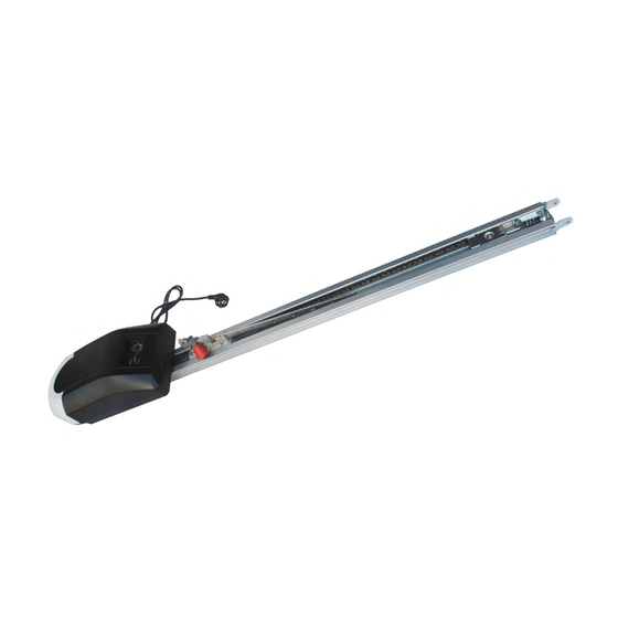
- Page 1 ® Garagentorantrieb/ Garage door opener/ Moteur pour portes de garage 800NM1 & 1000NM1 Bedienungsanleitung deutsch User manual english Manuel d'utilisation français heicko e-ast gmbH - Käthe-Kollwitz-Straße 15 - 51545 Waldbröl - www.heicko.de...
- Page 2 Montage- und Bedienungsanleitung Garagentorantriebe mit Kettenantrieb für Schwing- und Sektionaltore 800NM1 und 1000NM1 GT10.04_D...
-
Page 3: Table Of Contents
15. Techn. Daten ....................39 Im Servicefall wenden Sie sich bitte an Ihren Händler. Gerne helfen auch wir weiter. Schreiben Sie uns unter heicko@verkauf.de heicko e-ast gmbh Käthe-Kollwitz-Straße 15 D-51545 Waldbröl © heicko 2015 – Vervielfältigung und Nachdruck nur mit unserer Genehmigung... -
Page 4: Benutzerinformationen
1. Benutzerinformationen Achtung Lesen Sie diese Anleitung unbedingt vor der Montage und Inbetriebnahme! Beachten und befolgen Sie alle Anweisungen sowie Warnungen. Falsche Montage und/oder Anwendung kann zu schwerwiegenden Verletzungen und erheblichen Sachschäden führen. Bestimmungsgemäßer Gebrauch Der Antrieb ist ausschließlich zum Öffnen und Schließen von Schwing- und Sektionaltoren im Wohnbereich vorgesehen. -
Page 5: Sicherheitsbestimmungen Und -Vorschriften
Vor der Installation des Antriebs ist zu überprüfen, dass das Tor sich in einem mechanisch einwandfreien Zustand sowie im Gleichgewicht befindet und einwandfrei öffnet und schließt. Es ist darauf zu achten, dass das auslösende Teil für die Notentriegelung nicht an Dachträgersystemen oder sonstigen Aufbauten des Fahrzeuges hängen bleiben kann und dadurch die Notentriegelung unkontrolliert ausgelöst wird. -
Page 6: Zubehör Und Optionales Zubehör
2 Zubehör und optionales Zubehör Nicht im Lieferumfang Nicht im Lieferumfang Nicht im Lieferumfang... -
Page 7: Funktionen Und Vorteile
Funktionen und Vorteile 3.1 Geeignete Garagen-Tortypen Dieser Garagentorantrieb ist für Schwing- und Sektionaltore im Wohnbereich vorgesehen. Sektionaltor: Maximale Höhe 2,13 m Schwingtor: Maximale Höhe 2,23 m... -
Page 8: Funktionen
3.2 Funktionen Öffnet und schließt das Tor mit sanften Starts und Stopps Elektronische Einstellung der Endpunkte für präzise Torsteuerung Einfache Programmierung mit Bedienfeld Automatisch Umkehrder Bewegungsrichtung beim Auftreffen auf ein Hindernis Griff zur Notentriegelung Integrierte Beleuchtung für Sicht bei Dunkelheit – schaltet sich automatisch ein, wenn Antrieb aktiviert wird und automatisch aus nach ca. -
Page 9: Vormontage / Zusammenbau
5 Vormontage / Zusammenbau 5.1 Bauen Sie die Schienenteile zusammen, montieren den Schlitten und den Hebel für die Notentriegelung. VORSICHT: Verletzungsgefahr durch Einklemmen. Halten Sie Finger möglichst von den Fügestellen der Schienenteile fern. 5.2 Montieren Sie den Torarm (gerade oder gebogen) - Page 10 5.3 Positionieren und befestigen Sie die Kette mit dem Antriebskettentrad (29) Die Bohrungen zur Befestigung befinden sich auf der Motorseite der Schiene. 5.4 Spannen der Kette Die Spannvorrichtung für die Kette befindet sich auf der Torseite der Schiene Hinweis: Vor späteren Wartungsarbeiten an der Kette, ist immer mit der Notentriegelung der Schlitten zu lösen.
- Page 11 5.5 Schiene am Antrieb befestigen Achtung: Verwenden Sie hierzu ausschließlich die Befestigungsteile und –elemente aus dem Lieferumfang. Es besteht ansonsten die Gefahr, dass der Antrieb beschädigt wird und nicht sicher betrieben werden kann. Achtung: Der Antrieb darf während der Montagearbeiten nicht mit der Netzversorgung angeschlossen sein.
- Page 12 Deaktivieren bzw. entfernen Sie vor der Montage alle Verriegelungen und Sperren. Tragen Sie keine lose Kleidung oder Schmuck, welche sich in dem Antrieb oder sonstigen Teilen der Anlage verfangen können. Verbinden Sie niemals den Antrieb mit der Spannungsquelle, bevor sämtliche Montagearbeiten abgeschlossen sind und sich keine Personen mehr im Bereich von beweglichen Teilen befinden.
-
Page 13: Kopfwandlager Montieren
6.2 Kopfwandlager für Führungsschiene montieren Befestigen Sie die Kopfhalterung an der Wand über dem Garagentor (Kopfwand/Sturz) oder falls erforderlich, oberhalb des Tores an der Decke. Ist eine Montage direkt auf der Wand oder der Decke nicht möglich, so muss eine Hilfskonstruktion zur Befestigung erstellt werden. - Page 14 6. Montage (Fortsetzung) 6.3 Befestigen Sie die Schiene an dem Kopfwandlager Schiebe Sie die Schiene mit dem Gabelkopfende in die Kopfhalterung. Fixieren Sie die Schiene mit dem Bolzen (17) an der Kopfhalterung und sichern den Bolzen mit dem...
- Page 15 Federsplint (18). 6.4 Antrieb mit Schiene verbinden Achtung: Um Schäden an Garagentor, Schiene und Antrieb zu vermeiden, nehmen Sie bitte eine 2. Person zur Hilfe. Schritt 1: Befestigen Sie die "U" Bügel (5) auf der Schiene und verbinden das kurze Winkelstahlprofil (32) mit den Schrauben (19) an dem Bügel.
- Page 16 Schritt 2: Positionieren Sie die Schiene horizontal und messen Sie den Abstand zwischen Motor und Decke. Halten Sie Antrieb mit der Schiene in der Waage. Messen Sie den Abstand von beiden Seiten des Winkelprofils bis zur Decke. Schneiden Sie die zwei langen Winkelstahlprofile (12) entsprechend und verbinden diese mit dem kurzen Winkelprofil an der Schiene sowie dem zweiten kurzen Winkelprofil.
- Page 17 Zur direkten Montage an die Decke ohne die Winkelstahlprofile verwenden Sie Die Bügel (5) und (13). Warnung: Tragen Sie dafür Sorge, dass der Antrieb mit der Schiene mit geeigneten Verbindungsmitteln an der Decke dauerhaft befestigt ist. Es muss gewährleistet sein, dass die Befestigungsstellen den Antrieb mit der Schiene dauerhaft tragen und auftretende Kräfte durch das Eigengewicht sowie resultierende Kräfte aus dem Bewegungsablauf keinen Einfluss darauf haben.
-
Page 18: Torlager Für Zug-/Schubstange Montieren
6.5 Torlager für Zug-/Schubstange montieren Achtung: Vergewissern Sie sich, dass Tormaterial für die Befestigung geeignet ist. Bitte kontaktieren Sie dazu den Torhersteller und beschaffen sich über diesen ggf. Elemente zur Verstärkung. A Sektionaltore Schritt 1: Nutzen sie hierzu die bereits markierte vertikale Mittellinie für die Montage des Kopfwandlagers –... - Page 19 Schritt 2: Positionieren Sie den oberen Rand des Torlagers 5-10 cm unterhalb der Oberkante des Tores. Schritt 3: Markieren Sie die Stellen für die Bohrlöcher, bohren die Löcher und montieren das Torlager mit der Schraube (23).
- Page 20 B Schwingtore Montieren Sie das Torlager auch hier mittig zum Kopfwandlager und am obersten Rand des Tores. Kopfwand Kopflager Torlager Vertikale Mitte des Garagentors 6.6 Verbinden der Zug-/Schubstange mit Torlager und Transportschlitten Kann je nach Typ des Tores variieren. Folgen Sie den zutreffenden Anweisungen. A Sektionaltore Schritt 1: Schließen Sie das Tor.
- Page 21 Hinweis: Je nach baulicher Gegebenheit kann es erforderlich sein, dass die gerade Zug- /Schubstange als Verlängerung an die gebogene Zug-/Schubstange montiert werden muss – siehe folgende Abb. und verwenden Sie die Schrauben (19).
- Page 22 Schritt 3: Bringen Sie den Griff für die Notentriegelung in die horizontale Position. Der Transportschlitte rastet selbstständig ein, sobald der Antrieb aktiviert wird – siehe auch unter „Bedienung Transportschlitten mit Notentriegelung“. B Schwingtore Schritt 1: Schließen Sie das Tor. Lösen Sie den Transportschlitten durch betätigen der Notentriegelung.
- Page 23 Wichtig: Prüfen Sie manuell, ob das Tor sich leichtgängig bewegen sowie sich vollständig öffnen und schließen lässt. Ist das nicht der Fall, müssen alle Montageschritte auf eventuelle Fehler überprüft werden. Achtung: Montagefehler sind unbedingt zu beseitigen bzw. zu korrigieren. Andernfalls darf der Antrieb nicht in Betrieb genommen werden.
- Page 24 6.7 Installation der Lichtschranke (optionales Zubehör) Achtung: Da hier im Bewegungsbereich des Tores gearbeitet wird, ist vor Beginn der Arbeiten der Antrieb von der Spannungsversorgung zu trennen. Ein unbeabsichtigtes Einschalten des Antriebs muss unbedingt ausgeschlossen werden. Achtung: Montieren Sie das Sende- und das Empfängerteil der Lichtschranke so, dass keine Beeinflussungen durch direkte Sonneneinstrahlung und bewegliche Teile des Tores stattfinden können.
- Page 25 6.8 Den Antrieb anschließen und in Betrieb nehmen Achtung: Die Sicherheitsanweisungen und –vorschriften am Anfang dieser Anleitung sind unbedingt zu befolgen. Vor der Inbetriebnahme ist unbedingt zu überprüfen, ob diese Anweisungen und Vorschriften umgesetzt wurden. Andernfalls ist die Inbetriebnahme nicht zulässig. Haben Sie sich vergewissert, dass alle Anweisungen und Vorschriften umgesetzt sind und die gesamte Anlage fehlerfrei montiert und installiert ist, kann der Antrieb an die Netzversorgung angeschlossen werden.
- Page 26 7.2 Bedienfeld - Symbole Bedeutung der LED’s und der Tasten LED leuchtet LED blinkt LED ist aus Nicht drücken Drücken und Drücken und loslassen halten 8 LED's und 3 Tasten stehen für die Programmierung zur Verfügung: "P" Der jeweilige Programmiervorgang wird gewählt oder abgeschlossen. "+"...
-
Page 27: Einstellen Der Kraft Für Das Öffnen Und Schließen
Schritt 4: Drücken Sie die Taste P, um zu speichern. LED 4 blinkt. Siehe weiter 7.4. Die Endlage für „Offen ist jetzt gespeichert. 7.4 Eistellen der Endlage für „Geschlossen“ Schritt 1: LED 4 blinkt, drücken Sie jetzt die Taste "-", um das Tor zu schließen. Wenn das Garagentor vollständig geschlossen ist, lassen Sie die Taste "-"... - Page 28 Schritt 2: Drücken Sie wieder die Taste "P", LED4 blinkt jetzt. Schritt 3: Drücken Sie nochmals die Taste "P", LED6 blinkt jetzt. Schritt 4: Drücken Sie die Tasten "+" oder "-", um die Kraft nach den Erforderrnissen anzupassen. Sie können die Kraft von Stufe 1 bis 8 wählen und die jeweilige Stufe wird der blinkenden LED angezeigt.
- Page 29 7.6 Hinderniserkennung testen Achtung: Ohne ordnungsgemäß eingerichtete Einstellungen, kann ein sich schließendes Tor bei Personen (insbesondere Kleinkindern) erhebliche Verletzungen wie ebenso Sachschäden verursachen und daher muss nach den Einstellungen die Hinderniserkennung auf einwandfreie Funktion überprüft werden. die Hinderniserkennung monatlich überprüft werden ...
-
Page 30: Funktion Zum Automatischen Schließen Des Tores
8. Funktion zum automatischen Schließen des Tores (nach ca. 5 Minuten) deaktivieren Hinweis: vor Beginn der Arbeiten ist diese Anleitung vollständig zu lesen und die Sicherheitshinweise der Anleitung des Antriebes sind zu beachten! Halten Sie die Anleitung des Antriebes unbedingt und unmittelbar griffbereit. Hinweis: Änderungen der Einstellungen sind ausschließlich über das Bedienfeld am Antrieb möglich. - Page 31 Schritt 3: Drücken Sie nun innerhalb der nächsten 5 Sekunden 2 x die entsprechende Funktionstaste des Senders und LED 7 blinkt. Drücken Sie nun kurz zum speichern die Taste P und nun leuchtet LED 3. Der Vorgang kann beliebig oft wiederholt werden. Auf Sender mit mehreren Kanälen, kann auf jeden Kanal ggf.
- Page 32 Batterie Keypad-Funksender f. Wandmontage 9.3.3 Anwendung Tastenfeld Die Tastatur ist die Basis für die Anwendung. Sobald der Benutzer-PIN eigegeben ist, mit Taste ◄ oder ► bestätigt wird, ist der Aktivierungsbefehl übertragen. - Empfänger Kanal 1, wenn der Benutzer die Taste ◄drückt - Empfänger Kanal 2, wenn der Benutzer drückt ►.
- Page 33 9.3.4 Programmierung des Antriebes auf den Keypad-Funksender Schritt 1: Drücken und halten Sie die Taste "P", bis LED 7 blinkt. Schritt 2: Drücken Sie die Taste "+", alle LEDs sind aus, außer LED 7 leuchtet. Schritt 3: Geben Sie "11" ein und drücken kurz die ◄Taste, geben Sie "11" ein und drücken kurz die ◄Taste, alle LED‘s leuchten und LED 7 blinkt.
- Page 34 9.3.5 Ändern der PIN A) Kanal 1 - Beispiel: 1. Taste „0" drücken und halten 2. Taste Pfeil links „◄“ drücken und gemeinsam mit „0" loslassen. 3. Standard-PIN „11" (Werkseinstellung) eingeben und Pfeil links „◄“ drücken 4. Neue PIN eingeben, z.B. „147" und Pfeil links „◄“ drücken (PIN kann bis zu 8 Ziffern umfassen) 5.
- Page 35 10. Löschen von Funkcodes der Sender zum Empfänger (Antrieb) Achtung: Dass Durchführen dieser Funktion löscht sämtliche Funksenderinformation des Empfängers. Das bedeutet, dass der Antrieb mit keinem der Funksender, welche auf den Empfänger programmiert waren, mehr bedient werden kann. Diese Funksender müssen gemäß...
- Page 36 11. Transportschlitten - Notentriegelung Achtung Zur Vermeidung von schweren Verletzungen bei Personen und Sachschäden ist folgendes zu beachten: • Die Notentriegelung ist grundsätzlich nur bei geschlossenem Tor auszulösen. Schwache oder gebrochene Federn oder sonstige ungünstigen Umstände, können dazu beitragen, dass das Tor unerwartet wie ebenso unkontrolliert zufällt. •...
- Page 37 12. Fehlersuche Mögliche Ursache Abhilfe/Beseitigung Merkmal Das Garagentor ist verriegelt. Das Garagentor entriegeln. Die mechanischen Elemente Die Montage gemäß der und/oder Führungsschienen Der Antrieb stoppt Anleitung ggf. korrigieren. sind nicht korrekt montiert. sofort nach dem Startbefehl Die Einrichtung zur automatischen Die Abschaltung gemäß...
-
Page 38: Garantie
13. Garantie · Wir gewähren ab Verkaufsdatum 5 Jahre Garantie auf einwandfreie Funktion. Die gewährte Garantie beschränkt sich auf den Antrieb und die beweglichen Teile wie Kette, Antriebskettenrad und Transportschlitten. · Die Garantieleistung umfasst den wertgleichen und kostenlosen Ersatz oder ggf. die Reparatur des defekten Garagentorantriebes. -
Page 39: Optionaler Zubehör
SBE Lichtschranke: Erhöht die Sicherheit un d verhindert Verletzungen und Sachschäden. Kann an alle heicko e-ast Garagentorantriebe angeschlossen werden. FWH-1K Hand/Wand-Funksender: Für den Einsatz im Inneren der Garage oder / und Raum, um aus dem Wohnbereich Zugang zur Garage zu ermöglichen. Ist mit allen heicko e-ast Garagentorantrieben kompatibel. - Page 40 15. Technische Daten Art-Bezeichnung 800NM1 1000NM1 FK07-4K Funkfrequenz 433,92 433,92 433,92 Versorgungsspannung/-frequenz 230 V / 50 Hz 230 V / 50 Hz 12 V Motor 24 V DC 24 V DC Max. Zugkraft 800 N 1000 N Nennleistung 120 W...
- Page 41 Assembly and operating manual for garage door opener with chain drive for swing and sectional doors 800NM1 and 1000NM1 GT10.04_EN...
-
Page 42: Heicko E-Ast Gmbh Käthe-Kollwitz-Straße
14. Optional accessories ..............38 15.Technical data ................39 If service is required, please contact your dealer. We also assist further. Write to us at heicko@verkauf.de heicko e-ast gmbh Käthe-Kollwitz-Straße 15 D-51545 Waldbröl © heicko 2015 - Duplication and reproduction permitted only with our consent... - Page 43 1.User information Caution Please read these instructions carefully before assembly and commissioning! Observe and follow all instructions and warnings. Incorrect installation and/or use can cause serious injury or substantial property damage. Proper use The drive is designed exclusively for opening and closing of swinging and sectional doors in the living area.
- Page 44 Before installing the drive make sure that the door is in good mechanical condition, as well as being balanced and make sure it properly opens and closes. Make sure that the trigger part for the emergency release cannot get caught on the roof carrier systems or other structures of vehicles thus triggering the emergency release uncontrollably.
- Page 45 2 Accessories and optional accessories Not included in delivery Not included in delivery Not included in delivery...
- Page 46 Features and Benefits 3.1Appropriate types of garage doors This garage door operator is designed for swing and sectional doors in living areas. Sectional door: Maximum height 2.13 m Swinging door: Maximum height 2.23 m...
- Page 47 3.2Functions Opens and closes the door with gentle starts and stops, electronic adjustment of the endpoints for precise door control and easy programming with the control panel Automatic direction change of movement when striking an obstacle, handle for emergency release Integrated illumination for visibility in the dark - switches on automatically, if drive is activated, and off automatically after approx.
- Page 48 5 Pre-assembly / Assembly 5.1Assembly of rail parts, installing the carriage and the emergency release lever. CAUTION: Risk of injury from getting caught. Keep fingers as far as possible from the joining points of the rail sections. 5.2 Installing the door arm (straight or curved)
- Page 49 5.3Positioning and securing the chain with the drive chain (29) The holes for installation are located on the motor side of the rail. 5.4 Tightening the chain The tensioner for the chain is located on the door side of the rail Note: Prior to subsequent maintenance work on the chain, always activate the emergency release of the carriage.
- Page 50 5.5Attaching the drive rails Warning: Use only the installation parts and elements supplied. There is also the danger however, that the drive may be damaged and not safe to operate. Warning: During the installation work the drive should not be connected to the mains supply. Before starting work, the mains plug should be pulled-out from the wall socket.
- Page 51 Disable or remove all interlocks and lock before installation. Do not wear any loose clothing or jewellery, which may catch in the drive or other parts of the system. Never connect the drive to the power supply, before all installation work is completed and there are no people in the area of moving parts.
- Page 52 6.2Bearing wall mount for guide rail Attach headgear on the wall above the garage door (head wall/fall) or if necessary, above the door on the ceiling. If it is not possible to install directly to the wall or on the ceiling then an auxiliary construction for the installation needs to be built.
- Page 53 6. Installation (continued) 6.3Attach the rail to the head wall bearing Slide the rail with the clevis end into the headgear. Secure the rail with the bolt (17) to the head mount and secure the bolt with the...
- Page 54 spring clip (18). 6.4Connecting drive to the rail Warning: To avoid damage to the garage door, rail and drive, have a second person assist. Step 1: Fasten the "U" bracket (5) onto the rail and connect the short angular steel profile (32) with the screws (19) to the bracket.
- Page 55 Step 2: Position the rail horizontally and measure the distance between motor and ceiling. Balance the drive with the rail. Measure the distance from both sides of the angular profile up to the ceiling. Cut the two long angular steel profiles (12) accordingly and connect them with the short angular profile to the rail, as well as to the second short angular profile.
- Page 56 For direct installation to the ceiling without the angular steel profiles, use the brackets (5) and (13). Warning: Ensure that the drive and rail are permanently attached to the ceiling with suitable means of connection. Make sure the attachment points can permanently hold the drive along with the rail and any forces occurring due to the weight and from any movements do not have any affect.
- Page 57 6.5Door bearing pull / push rod assembly Warning: Make sure that the door material is suitable for attachment. Please contact the manufacturer of the door and if necessary obtain strengthening elements. A Sectional doors Step 1: Use the already marked vertical centreline for the installation of the head wall bearing - see section 6.2.
- Page 58 Step 2: Position the top edge of the door bearing 5-10 cm below the top edge of the door. Step 3: Mark the locations for the holes, drill the holes and install the door bearing with screw (23).
- Page 59 B Swing doors Mount the door bearings here centrally to the head wall bracket and the top edge of the door. Head wall (Finished ceiling) Head bearing Door bearing Vertical centre of the garage door 6.6Connecting the pull / push rod with the door bearing and carriage May vary depending on the type of door.
- Page 60 Note: Depending on the structural condition, the straight pull / push rod may need to be installed as an extension to the curved pull / push rod - see following figure and use the screws (19).
- Page 61 Step 3: Attach the handle for the emergency release in the horizontal position. The carriage engages independently as soon as the drive is activated - see also under "Operating Transport Carriage with Emergency Release". B Swing doors Step 1: Close the door. Release the transport carriage by actuating the emergency release. Step 2: Attach the straight pull / push rod to the door bearings for the rod with the locking bolt and secure it with the safety clip.
- Page 62 Important: Check manually that the door can be moved easily and completely opened and closed. If this is not the case, all installation steps must be checked for any errors. Warning: Installation errors must be eliminated or corrected. Otherwise, the drive should not be put into operation.
- Page 63 6.7Installing of the light barrier (optional) Warning: As work here is in the movement area of the door, the drive should be separated from the power supply before commencing any work. Unintentional switching on of the drive must be absolutely excluded. Warning: Install the transmitter and the receiver of the light barrier so that no interference can take place through direct sunlight and moving parts of the door.
- Page 64 6.8Connect the drive and put it into operation Warning: The safety instructions and regulations at the beginning of this manual must be followed. Before commissioning make sure these instructions and regulations were implemented. Otherwise commissioning is not allowed. Once you have made sure that all the instructions and regulations are implemented and the entire system is assembled and installed without error, the drive can be connected to the mains supply.
- Page 65 7.2 Control Panel - icons Meaning of the LED's and the buttons Press and Press and LED lights up LED flashes LED is off Do not push release hold 8 LED's and 3 buttons are available for programming: "P", the respective programming operation is selected or completed. "+"...
- Page 66 Step 4: Press the P button to save. LED 4 flashes. See further 7.4. The end position for "Open" is now stored. 7.4Setting the end position "Closed" Step 1: LED 4 flashes, now press the button "-", to close the door. When the garage door is fully closed, release the button "-".
- Page 67 Step 2: Press the button "P" again, LED4 now flashing. Step 3: Press the button "P" once again, LED6 now flashing. Step 4: Press the buttons "+" or "-", to adjust force to suit the circumstances. You can select the power from level 1 to 8 and the respective level flashes in the LED display. If you have chosen the right level, press "P"...
- Page 68 7.6Test obstacle detection Warning: Without properly adjusted settings, a closing door can cause severe injuries to people (especially small children) and property damage therefore · after adjustment of the obstacle detection check for flawless functioning. · the obstacle detection must be checked monthly The obstacle detection must respond when closing if there is contact with a 5 cm high object lying on the floor.
- Page 69 8. Deactivate the automatic closing function of the door drive (about 5 minutes) Note: before starting work these instructions must be read completely and the safety instructions of the manual of the drive must be follow! Keep the instruction of the door drive necessarily and directly at hand.
- Page 70 Step 3: Within the next 5 seconds, press the appropriate function button on the transmitter 2 x and LED 7 flashes. Press briefly to the store button P and LED 3 now lights up. The operation can be repeated any number of times. With transmitters of this series that have more than one channel, another garage door can be opened on each channel if required.
- Page 71 Batteries Keypad - radio transmitter for wall installation 9.3.3 Application keypad The keyboard is the basis for the application. Once the user's PIN is entered, pressing ◄ or ► confirms, the activation command is transmitted. -Receiver channel 1 if the user presses the ◄ button -Receiver channel 2 if the user presses the ►...
- Page 72 9.3.4 Programming the drive on the keypad transmitter step 1: Press and hold the "P" button until LED 7 flashes. Step 2: Press the button "+", all LEDs are off, except LED 7. Step 3: Enter "11" and briefly press the ◄ button, all LEDs light up and LED 7 flashes. The keypad transmitter is now programmed.
- Page 73 9.3.5 Changing the PIN code A) Channel 1 – sample: 1. Press and hold "0" key 2. press button arrow left "◄" and release together with "0". 3. Enter default PIN "11" (factory setting) and press arrow left "◄" 4. Enter new PIN, for example "147" and press arrow left "◄" (PIN can be include up to 8 digits) 5.
- Page 74 10. Deleting radio codes of the transmitter to the receiver (drive) Warning: Performing this function deletes all radio information of the receiver. This means that the drive can no longer be used with any of the radio transmitters that were programmed for the receiver.
- Page 75 11. Transport carriage - emergency release Warning To avoid serious injury to persons and damage to property, please note the following: • The emergency release should only be triggered when the door is closed. Weak or broken springs or any other unfavourable circumstances, can contribute to the door opening unexpectedly and uncontrollably.
- Page 76 12. Troubleshooting Possible cause Solution/elimination Feature The garage door is locked. Unlock the garage door The mechanical elements or Correct the installation guide rails are not correctly according to the manual, if The drive stops installed necessary immediately after the start command The device for the automatic Correct the switch-off switch-off is not adjusted correctly...
- Page 77 13. Guarantee · We grant 5 years warranty from the sales date for proper operation. · The warranty granted is limited to the drive and moving parts such as chain, drive sprocket and transport carriage. · The warranty covers the value of the same and, if necessary, free replacement or repair of the defective garage door.
- Page 78 FWH-1 K Hand/wall - radio transmitter: For use inside the garage and/or room to allow access to the garage from the living area. Is compatible with all heicko e-ast garage door openers.
- Page 79 15. Technical data Designation of item 800NM1 1000NM1 FK07-4K Radio frequency 433,92 433,92 433,92 Supply voltage/frequenzy 230 V / 50 Hz 230 V / 50 Hz 12 V Motor 24 V DC 24 V DC Max. tensile force 800 N...
- Page 80 Instructions de montage et d'utilisation de système d'entraînement à chaîne pour portes de garage basculantes et sectionnelles 800NM1 and 1000NM1 GT10.04_FR...
- Page 81 Pour toute opération de maintenance, veuillez contacter votre fournisseur. Nous demeurons également à votre disposition pour toute assistance supplémentaire. Contactez-nous par écrit à l'adresse heicko@verkauf.de. heicko e-ast gmbh Käthe-Kollwitz-Straße 15 D-51545 Waldbröl © heicko 2015 – La distribution et l'impression du présent document ne doivent pas être...
-
Page 82: Informations D'utilisation
1.Informations d'utilisation Attention Il est impératif de prendre connaissance des présentes instructions avant toute opération de montage ou de mise en service. La prise en compte et le respect de toutes les instructions et tous les avertissements fournis est nécessaire. Tout défaut de montage et/ou d'utilisation du matériel est susceptible de causer de graves blessures ou des dégâts importants au niveau du matériel. -
Page 83: Dispositions Et Règlementation Relatives À La Sécurité
Avant l'installation du système d'entraînement, il est nécessaire de vérifier l'intégrité de l'état mécanique de la porte et de son déplacement, ainsi que son équilibrage. Il est également nécessaire de s'assurer que le déclencher de déverrouillage d'urgence ne puisse pas être accroché par les barres de toit ou toute autre dispositif installé sur votre véhicule, risquant de causer le déverrouillage intempestif du système. -
Page 84: Accessoires Et Équipement En Option
2 Accessoires et équipement en option Non inclus dans la livraison Non inclus dans la livraison Non inclus dans la livraison... -
Page 85: Fonctions Et Avantages
Fonctions et avantages 3.1Types de porte de garage appropriés Ce système d'entraînement est destiné aux portes de garage basculantes et sectionnelles utilisées en milieu résidentiel. Porte sectionnelle : hauteur maximale de 2,13 m Porte basculante : hauteur maximale de 2,23 m... -
Page 86: Fonctions
3.2Fonctions Ouverture et fermeture de porte de garage avec démarrage et arrêt en douceur Réglage électronique des points de fin de course pour une commande précise de la porte Programmation simplifiée à l'aide du panneau de commande Permutation automatique du sens de déplacement en cas de rencontre d'un obstacle Poignée de déverrouillage d'urgence Éclairage intégré... -
Page 87: Pré-Montage/Assemblage
5Pré-montage/assemblage 5.1Assemblage des pièces du rail de guidage et montage du chariot coulissant et du levier de déverrouillage d'urgence ATTENTION : Danger de blessure par pincement ! Maintenez vos doigts aussi loin que possible du point d'assemblage des pièces. 5.2Montage de la tige de transmission (droite ou coudée) -
Page 88: Positionnement Et Fixation De La Chaîne
5.3Positionnement et fixation de la chaîne à l'aide du pignon d'entraînement (29) Les trous de fixation sont situés sur le rail, du côté du moteur. 5.4 Tension de la chaîne Le dispositif de tension de la chaîne est situé sur le rail, du côté de la porte. Remarque : par la suite, avant toute opération de maintenance, le chariot doit toujours être desserré... - Page 89 5.5Fixation du rail au système d'entraînement Attention : pour cette opération, utilisez uniquement les pièces et éléments de fixation fournis. Dans le cas contraire, le système d'entraînement risque d'être endommagé et la sécurité de son fonctionnement compromise. Attention : au cours du montage, le système d'entraînement ne soit pas être raccordé à l'alimentation électrique.
-
Page 90: Positionnement Du Support De Linteau
Avant le montage, désactivez ou retirez tous les dispositifs de verrouillage. Évite le port de vêtements amples ou de bijoux, ceux-ci présentant le risque d'être happés par le système d'entraînement ou d'autres parties de l'installation. Ne raccordez jamais le système à l'alimentation électrique avant la fin de toutes les étapes du montage, ni en présence de personnes dans la zone de mouvement des pièces mobiles. -
Page 91: Montage Du Support De Linteau
6.2Montage du support de linteau pour le rail de guidage Fixez le support de linteau au mur, au-dessus de la porte de garage (linteau) ou, le cas échéant, au plafond au-dessus de la porte. Si la fixation directe au mur ou au plafond est impossible, une structure de support doit être premièrement posée. - Page 92 6. Montage (suite) 6.3Fixation du rail au support de linteau Insérez les deux lames métalliques situées à l'extrémité du rail dans le support de linteau. Fixez le rail au support de linteau à l'aide de la tige (17) prévue à cet effet et fixez la tige à l'aide de la...
- Page 93 goupille bêta (18). 6.4Fixation du rail au système d'entraînement Attention : afin d'éviter tout dommage au niveau de la porte de garage, faites-vous seconder par quelqu'un. Étape 1 : Fixez l'étrier (5) sur le rail et fixez le profil d'angle court en acier (32) à l'étrier à l'aide des vis (19).
- Page 94 Étape 2 : positionnez le rail à l'horizontale et mesurez l'espacement entre le moteur et le plafond. Maintenez le système d'entraînement et le rail à l'horizontale. Mesurez l'espacement entre les deux côtés du profil d'angle et le plafond. Découpez les deux profils d'angle longs en acier (12) selon la masure et fixez-les au rail avec le profil d'angle court, ainsi que le second profil court.
- Page 95 Pour un montage direct au plafond, sans profil d'angle en acier, utilisez les chevilles (5) et (13). Attention : veillez à ancrer le système d'entraînement et le rail de manière appropriée afin d'assurer une fixation durable du système au plafond. Pour cela, assurez-vous que l'emplacement de fixation du système d'entraînement et du rail au plafond est à...
-
Page 96: Montage Du Support Sur Porte Pour La Tige De Transmission
6.5Montage du support sur porte pour la tige de transmission Attention : assurez-vous que le matériau est adapté à une fixation sur la porte. Pour ce faire, contactez le fabricant de la porte et, le cas échéant, procurez-vous les éléments de renforcement nécessaires. - Page 97 Étape 2 : positionnez le rebord supérieur du support sur porte à 5-10 cm du rebord supérieur de la porte. Étape 3 : marquez l'emplacement des trous de perçage, percez les trous et fixez le support à l'aide des vis (23).
- Page 98 B Portes basculantes Dans ce cas également, alignez le support au support de linteau et fixez-le au niveau du rebord supérieur de la porte. Linteau (voir ci-dessus ) Support de linteau Support sur porte Ligne médiane verticale de la porte de garage 6.6Fixation de la tige de transmission au support de la porte et au chariot coulissant Cette opération peut varier en fonction du type de porte.
- Page 99 Remarque : en fonction de la configuration du montage, il peut être nécessaire de prolonger la tige de transmission coudée à l'aide de la tige droite. Pour ce faire, reportez-vous à l'illustration suivante en utilisant les vis (19).
- Page 100 Étape 3 : positionnez la poignée de déverrouillage d'urgence à l'horizontale. Le chariot coulissant s'enclenche tout seul à l'activation du système d'entraînement. Reportez-vous également à la section « Utilisation du chariot coulissant et du déverrouillage d'urgence ». B Portes basculantes Étape 1 : fermez la porte.
- Page 101 Important : vérifiez manuellement que la porte coulisse sans heurt et peut se fermer et s'ouvrir entièrement. Si tel n'est pas le cas, toutes les étapes du montage doivent être vérifiées afin de déterminer l'erreur de montage. Attention : les erreurs de montage doivent impérativement être éliminées et corrigées. Dans le cas contraire, le système d'entraînement ne doit pas être mis en fonctionnement.
-
Page 102: Installation Du Détecteur Lumineux (Optionnel)
6.7Installation du détecteur lumineux (optionnel) Attention : cette opération étant effectuée dans la zone de mouvement de la porte, le système d'entraînement doit être débranché de l'alimentation électrique avant de commencer. Tout actionnement accidentel du système d'entraînement doit impérativement être évité. Attention : montez l'émetteur et le récepteur du détecteur lumineux de manière à... - Page 103 6.8Mise en fonctionnement du système d'entraînement Attention : les instructions et directives de sécurité fournies au début de ce document doivent impérativement être prises en compte. Avant la mise en service, il est impératif de vérifier que ces instructions et directives ont bien été respectées. La mise en service n'est pas autorisée sans cette précaution.
-
Page 104: Panneau De Commande Et Symboles
7.2 Panneau de commande et symboles Signification des touches et témoins lumineux Appuyer et Appuyer et Témoin allumé Témoin clignotant Témoin est éteinte Ne pas relâcher maintenir La programmation est effectuée au moyen de 8 témoins et 3 touches : "P"... -
Page 105: Réglage Du Point De Fin De Course À La Fermeture
Étape 4 : appuyez sur la touche "P" pour enregistrer la position. Le témoin 4 clignote (voir section 7.4). Le point de fin de course à l'ouverture est maintenant enregistré. 7.4Réglage du point de fin de course à la fermeture Étape 1 : le témoin 4 clignote. - Page 106 Étape 2 : appuyez à nouveau sur la touche "P". Le témoin 4 clignote. Étape 3 : appuyez à nouveau sur la touche "P". Le témoin 6 clignote. Étape 4 : Appuyez sur les touches "+" et "-" pour ajuster la puissance à vos besoins. Vous pouvez sélectionner un niveau de puissance compris entre 1 et 8.
-
Page 107: Test De La Détection D'obstacle
7.6Test de la détection d'obstacle Attention : en cas de réglage inapproprié, la porte risque de causer des blessures graves (en particulier aux enfants en bas âge) ou des dégâts matériels importants lors de sa fermeture et, par conséquent : ·... -
Page 108: Désactiver La Fonction De Fermeture Automatique De La Porte
8.Désactiver la fonction de fermeture automatique de la porte Remarque: avant de commencer les travaux de ces instructions doivent être lues complètement et la sécurité des instructions de l'entraînement doivent être respectées! Gardez l'instruction de l'opérateur nécessairement et directement à portée de main. Remarque: Les modifications apportées aux paramètres sont uniquement à... -
Page 109: Changement De La Pile D'une Télécommande
Étape3 : dans les 5 secondes suivantes, appuyez alors 2 x sur la touche de fonction correspondante de la télécommande. Le témoin 7 clignote. Appuyez ensuite brièvement sur la touche "P" pour enregistrer le paramètre. Le témoin 3 s'allume. Le processus peut être réitéré autant de fois que nécessaire. Sur les télécommandes multicanaux, chaque canal peut, le cas échéant, être configuré... - Page 110 Pile Télécommande à clavier pour montage mural 9.3.3Utilisation du clavier L'utilisation de l'appareil repose entièrement sur le clavier. À la saisie du code PIN d'un utilisateur, après confirmation à l'aide de la touche ◄ ou ►, la commande d'activation est transmise.
- Page 111 9.3.4 Programmation du système d'entraînement à l'aide de la télécommande à clavier Étape 1 : appuyez et maintenez la touche "P" jusqu'au clignotement du témoin 7. Étape 2 : appuyez sur la touche "+". Tous les témoins s'éteignent à l'exception du témoin 7. Étape 3 :saisissez la combinaison "11"...
- Page 112 9.3.5 Modification du code PIN A) Exemple - le canal 1: 1.Appuyez sur la touche "0" et, en la maintenant appuyée, appuyez sur "◄". 2.Relâchez la touche "0" et "◄". 3.Saisissez ensuite la combinaison suivante : "11“ et "◄". 4.Saisissez le nouveau code PIN (jusqu'à 8 chiffres). Par exemple : "147" et "◄". 5.Confirmez ensuite la combinaison "147"...
- Page 113 10. Suppression des codes d'émission de la télécommande au système d'entraînement (récepteur) A t t e n t i o n : l ' e x é c u t i o n d e c e t t e o p é r a t i o n s u p p r i m e t o u t e s l e s i n f o r m a t i o n s d e télécommande du récepteur.
-
Page 114: Utilisation Du Chariot Coulissant Et Du Déverrouillage D'urgence
11. Utilisation du chariot coulissant et du déverrouillage d'urgence Attention Afin d'éviter tout risque de blessure grave aux personnes ou de dégâts matériels importants, les points suivants sont à prendre en compte : • Le déverrouillage d'urgence doit uniquement être actionné lorsque la porte est fermée. Si les ressorts sont trop faibles ou détériorés, ou en d'autres conditions non désirées, il risque d'en résulter une fermeture inattendue et par conséquent incontrôlée de la porte. - Page 115 12. Recherche de défaillances Origine possible Réparation/Élimination Signe La porte du garage est verrouillée. Déverrouillez la porte du garage. Les éléments mécaniques et/ou Corriger le montage en Le système rails de guidage ne sont pas suivant les instructions. d'entraînement montés correctement. s'arrête immédiatement après la commande...
-
Page 116: Garantie
13. Garantie · Nous garantissons un fonctionnement sans défaut pendant une durée de 5 ans. · La validité de la garantie est restreinte au système d'entraînement et aux pièces mobiles telles que la chaîne, le pignon d'entraînement et le chariot coulissant. ·... -
Page 117: Accessoires En Option
14 Accessoires et équipement en option FK07-4K Télécommande porte-clés : Compatible avec tous les systèmes d'entraînement de porte de garage Sol Royal. Accessoires en option FWHZ-2K Télécommande à clavier pour montage mural : Adapté à un montage en extérieur. Possibilité d'activation par code PIN personnalisé. Compatible avec tous les systèmes d'entraînement de porte de garage Sol Royal. - Page 118 15. Caractéristiques techniques 800NM1 1000NM1 FK07-4K Article Fréquence radio 433,92 433,92 433,92 Tension et fréquence d'alimentation 230 V / 50 Hz 230 V / 50 Hz 12 V Moteur 24 V CC 24 V CC Force de traction max. 800 N...
Need help?
Do you have a question about the 800NM1 and is the answer not in the manual?
Questions and answers