Advertisement
Table of Contents
- 1 Important Installation Instructions
- 2 Specifications
- 3 Entrapment Protection
- 4 Installation Instructions
- 5 Operator Mounting
- 6 Drive Chain Adjustment
- 7 Limit Switch Adjustment
- 8 Wiring Instructions
- 9 Control Overview
- 10 Auxiliary Function
- 11 Timer Instruction
- 12 Light Indication
- 13 Important Safety Instructions
- 14 Read and Follow All Instructions
- 15 Emergency Manual Operation
- 16 Maintenance Instructions
- Download this manual
Advertisement
Table of Contents

Summary of Contents for Cornell SGH Series
- Page 1 INSTALLATION INSTRUCTIONS OPERATION MANUAL SGH Series UL325-2010 Compliant Commercial and Industrial Door Operator Logic Control Continuous Duty...
-
Page 2: Important Installation Instructions
14. If the operator is provided with an auxiliary chain operator, the hand chain should be kept inside the chain bag when operating electrically. 15. For products having a manual release, instruct the end user on the operation of the manual release. SGH Series REVISION # 0002 DATE: 10/09/2012... -
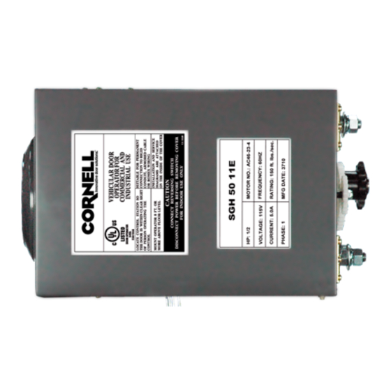
Page 3: Specifications
1. Non-contact device (photo eye) can be used on doors up to 45 ft. wide (or maximum rated range of device if less than 45 ft.). Use a sensing edge to provide entrapment protection on doors over 45 ft. wide. 2. Sensing edge can be used on all doors. SGH Series REVISION # 0002 DATE: 10/09/2012... -
Page 4: Installation Instructions
Consult factory for any changes. (LH=LS and RA, RH=RS and LA) Operators mounted in alternate positions (LA, RA) require the long mounting legs in lieu of the standard short mounting legs. SGH Series REVISION # 0002 DATE: 10/09/2012... - Page 5 Consult factory for any changes. (LH=LS and RA, RH=RS and LA) Operators mounted in alternate positions (LA, RA) require a straight mounting plate in lieu of the standard bent plate. SGH Series REVISION # 0002 DATE: 10/09/2012...
-
Page 6: Operator Mounting
5. Finally, mount the operator to the three legs and tighten (for 1/2 and 3/4hp only). For other horsepowers, mount the operator to the mounting plate. (Figure 1 for 1/2hp and 3/4hp) (Figure 2 for 1hp and 1½hp) SGH Series REVISION # 0002 DATE: 10/09/2012... - Page 7 It may be necessary to field brace the operator/bracket. Door Sprocket Operator Drive Sprocket Correct Incorrect (Figure 1 for 1/2hp and 3/4hp) Door Sprocket Operator Drive Sprocket Correct Incorrect (Figure 2 for 1hp and 1½hp) SGH Series REVISION # 0002 DATE: 10/09/2012...
-
Page 8: Drive Chain Adjustment
Drive Sprocket Drive Sprocket (Figure 1 for 1/2hp and 3/4hp) Drive Chain Drive Chain Door Sprocket Door Sprocket 1/4" 1/4" Drive Sprocket Drive Sprocket 1½ (Figure 2 for 1hp and SGH Series REVISION # 0002 DATE: 10/09/2012... - Page 9 HAND CHAIN ADJUSTMENT Cut and reconnect chain with different color link provided. Chain Holder Optional SGH Series REVISION # 0002 DATE: 10/09/2012...
-
Page 10: Limit Switch Adjustment
7. Micro switch (A or B) can be adjusted to accommodate sensing edge cut-off position. NOTE: “C” is usually the opening side and “D” is usually the closing side. SGH Series REVISION # 0002 DATE: 10/09/2012... -
Page 11: Wiring Instructions
WARNING To avoid damage to door and operator, make all door locks inoperative. Secure lock(s) in the unlocked position, or install electrical interlocks to WARNING prevent operation with the lock engaged. SGH Series REVISION # 0002 DATE: 10/09/2012... - Page 12 1266 Monitored photo Optical Edge Sensors and Photo Eyes, Models OPTOEDGE, FRABA Inc. OPTOEYE; Part Nos. OSE-T, OSE-R, OSE-P, OPE. Please refer to sensing device manufacturer for specific installation and maintenance requirements. Note: SGH Series REVISION # 0002 DATE: 10/09/2012...
- Page 13 Changing from left hand to right hand or vice versa could result in change WARNING of control wiring. Consult factory for details. 5. After installation, be sure that the operator, controls, and sensing edge or other entrapment protection devices have been tested and function properly. SGH Series REVISION # 0002 DATE: 10/09/2012...
-
Page 14: Control Overview
IR: P5&P6 ELR:E5&E6 1.Stop 7&8 Close (ELR-End of line resistor). 2.Open Warning 3.Close signal Single-phase power source 4.Com 24VAC See operator plate for correct A-1. voltage. A-3. 9&10 23&24 External nterlock Timer Defeat SGH Series REVISION # 0002 DATE: 10/09/2012... -
Page 15: Auxiliary Function
B-1. CN12 CN13 CN14 1. 1&2 Close limit dry contact 2. 3&4 Open limit dry contact 24VDC MAX0.5A B-2. Open door B-3. Radio control Close door Push button 24VDC Stop door SGH Series REVISION # 0002 DATE: 10/09/2012... -
Page 16: Timer Instruction
BUZZER Select, to select timer set. (1) Timer 1 – Mid‐open timer : Timer starts counting when door leaves close limit. Door stops after opening for set time. Pressing open again at mid‐open position will cause door to open to open limit. Timer 2 – Timer to close : Timer is active when door stops and is not at close limit. Timer 3 – Door Open Warning Timer : Timer is active when door leaves close limit. When time is up, contact will close. See figure C‐1. Timer LED – is lit when a value is set. Timer LED flashing when counting down. LED12, LED13 & LED14. Terminals 9 and 10 External timer disable switch connection – jump to disable all timer funtions or install a switch beteen 9 and 10. When switch is open all timers are enabled and when switch is closed all timers are disabled. SGH Series REVISION # 0002 DATE: 10/09/2012... - Page 17 Min. 1 Sec Min. 1 Sec For save SELECT SET TIMER RESET DOWN Press SET until Timer 2 light is lit. Continue to set Timer 2 or no action until counter light is lit. SGH Series REVISION # 0002 DATE: 10/09/2012...
- Page 18 Min. 1 Sec Min. 1 Sec For save SELECT DOWN SET TIMER RESET Press SET until Timer 1 light is lit. Continue to set Timer 1 or no action until counter light is lit. SGH Series REVISION # 0002 DATE: 10/09/2012...
- Page 19 1) Must switch Timer Switch to ON. (See figure A-2 on Page 13 for location.) 2) Must remove jumper on Terminal PCB-CN2 (23,24). (See figure A-1 on Page 13 for location.) SGH Series REVISION # 0002 DATE: 10/09/2012...
-
Page 20: Light Indication
10 26 6 ON: Activated. LED6 ELR OFF: Not activated. ON: Connected with ELR. OFF: Not connecting or damaged ELR. LED11 N/O type sensing edge. ON: Sensing device is activated. OFF: Not activated. SGH Series REVISION # 0002 DATE: 10/09/2012... - Page 21 SGH Series REVISION # 0002 DATE: 10/09/2012...
- Page 22 SGH Series REVISION # 0002 DATE: 10/09/2012...
- Page 23 SGH Series REVISION # 0002 DATE: 10/09/2012...
- Page 24 SGH Series REVISION # 0002 DATE: 10/09/2012...
- Page 25 SGH Series REVISION # 0002 DATE: 10/09/2012...
- Page 26 SGH Series REVISION # 0002 DATE: 10/09/2012...
- Page 27 SGH Series REVISION # 0002 DATE: 10/09/2012...
- Page 28 SGH Series REVISION # 0002 DATE: 10/09/2012...
- Page 29 SGH Series REVISION # 0002 DATE: 10/09/2012...
- Page 30 SGH Series REVISION # 0002 DATE: 10/09/2012...
- Page 31 SGH Series REVISION # 0002 DATE: 10/09/2012...
- Page 32 SGH Series REVISION # 0002 DATE: 10/09/2012...
- Page 33 Reference SGH series terminal connections Control Station External Interlock Timer Defeat Phote eyes ELR sensing Push Button or IR sensing edge edge Close Jump when no external interlock warning Stop Open Close is connected. signal 24VDC Control panel is wired with momentary pressure open and constant pressure close.
-
Page 34: Important Safety Instructions
6. KEEP DOORS PROPERLY OPERATING AND BALANCED. See Door Manufacturer’s Owner’s Manual. An improperly operating or balanced door could cause severe injury or death. Have trained door systems technician make repairs to cables, spring assemblies, and other hardware. SAVE THESE INSTRUCTIONS. SGH Series REVISION # 0002 DATE: 10/09/2012... -
Page 35: Emergency Manual Operation
Put the hand chain back into the chain bag, before operating the door again electrically. Turn off power to the operator before manually operating the door. WARNING Hand chain must be kept inside chain bag when operating electrically. WARNING SGH Series REVISION # 0002 DATE: 10/09/2012... -
Page 36: Maintenance Instructions
Do not place hands or tools in or near the operator when the power is connected or when testing control or sensing devices. Always disconnect WARNING power before servicing or adjusting the operator. U.S. GEAR Covered under US Pat. #6,055,885, #6,900,602 and additional patents pending. SGH Series REVISION # 0002 DATE: 10/09/2012... - Page 37 Warning ! Warning ! Remove Jump Remove Jump Pin First "A" Pin First "A" OPEN OPEN OPE N CLOSE CLOSE CLOSE "A" "A" Remove Remove Jump pin Jump pin STOP ST OP SGH Series REVISION # 0002 DATE: 10/09/2012...
- Page 38 KEY LOCKOUT 3-2 BUTTON STOP STOP OPEN OPEN OPEN OPEN OPEN Key switch OPEN CLOSE CLOSE CLOSE CLOSE CLOSE STOP STOP STOP STOP CLOSE Ceiling Pull Switch Station CLOSE/OPEN JUMP CLOSE/OPEN RADIO SGH Series REVISION # 0002 DATE: 10/09/2012...
Need help?
Do you have a question about the SGH Series and is the answer not in the manual?
Questions and answers