
Related Manuals for dbx ZC-1


Summary of Contents for dbx ZC-1
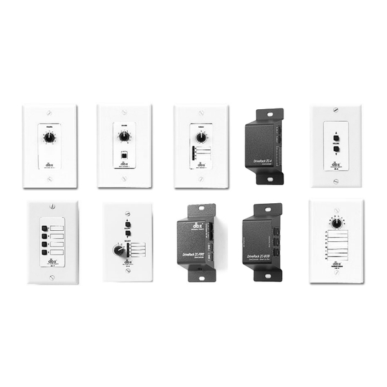
- Page 1 ® Dri v eRack /ZonePRO ™ ® ZC Series Wall-Mounted Zone Controllers Series ZC-1-4 ZC-6-9 ZC-Fire ZC-BOB User Guide...
- Page 2 8760 S. Sandy Parkway Sandy, Utah 84070, USA declares that the product: Product name: dbx Zone Controllers Models: ZC1, 2, 3, 4, 6, 7, 8, 9, FIRE and BOB Note: Product name may be suffixed by the letters -EU. Product option: none...
- Page 3 ZC-Remote Control Wall Controllers Zone Controller Wiring The Zone Controllers, (ZC-1, ZC-2, ZC-3, ZC-4, ZC-6, ZC-7, ZC-8, ZC-9, and ZC-Fire) can be wired serially or in parallel. To wire in series each Zone Controller must have an iden- tification or zone number chosen using the DIP switches on the side of the controller (see diagram A).
- Page 4 USER GUIDE ZC-Remote Control Wall Controllers Diagram C Diagram D ZC-4 Binary App notes Setting Switches SW1-SW4 correspond to switch inputs 1-4 on the ZC4's EuroBlock connector.Each switch connected to the ZC4 must be a Dual Pole Single Throw (DPST). One pole of each switch should be connected to the ground reference on the ZC4's EuroBlock con- nector while the other pole should be connected to the +V refer- ence.
- Page 5 • Cable runs of up to 1,000 feet may be achieved using “Home Run” wiring. An example of this is shown in Diagram H. A dbx Zone Controller Break Out Box (dbx ZC-BOB) is used to paral- lel several cable runs. It should be noted that a 1,000 foot cable with a single Zone Controller may be connected directly to the DriveRack or ZonePro.
- Page 6 USER GUIDE ZC-Remote Control Wall Controllers Diagram F Diagram G Diagram H ® DriveRack ® /ZonePRO ™ User Manual...
- Page 7 USER GUIDE ZC-Remote Control Wall Controllers Cable Spec: Cat5 Cable - 4-Twisted Pairs of 24AWG wire RJ-45 RJ-45 (8-Position) (8-Position) White/Orange -VREF Orange -Zone 1 White/Green -Zone 2 Green -Zone 3 White/Blue -Zone 4 Blue -Zone 5 White/Brown -Zone 6 Brown -GND Zone Controller Compatibility Chart...
- Page 8 VW-1 or higher. Common NEC designations which meet this rating include: CMP, CMR, CMG, CM and CMX. Specifications: Connections: ZC-1, ZC-2, ZC-3, ZC-6, ZC-7, ZC-8 and ZC-9 Connectors: (2) RJ-45 ZC-4 Connectors: (2) RJ-45, (1) 6-pin Phoenix ZC-BOB Connectors: (7) RJ-45 ZC-Fire Connectors (2) RJ-45, (2) 2-Pin Phoenix Wiring: Maximum Cable Length depends on number of Zone Controllers and wiring schematic.
Need help?
Do you have a question about the ZC-1 and is the answer not in the manual?
Questions and answers