Table of Contents
Advertisement
Advertisement
Table of Contents
Troubleshooting

Related Manuals for Distek Premiere 5100

Summary of Contents for Distek Premiere 5100
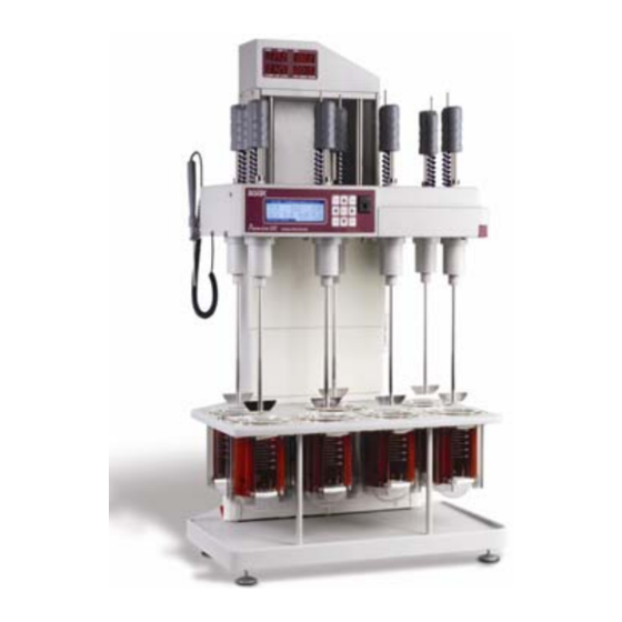
- Page 1 Premiere 5100 Dissolution Test System Operation Manual...
- Page 2 About This Manual Distek Premiere 5100 Dissolution Test System Operation Manual Document # 3851-0020 Distek, Inc. 121 North Center Dr. • North Brunswick, NJ 08902 Phone 732.422.7585 • Fax 732.422.7310 http://www.distekinc.com Operation Manual: Model 5100...
- Page 3 IBM and IBM PC are registered trademarks of IBM Corp. CenterChek, HeightChek, RPMChek, ShaftChek, and TempChek are trademarks of DISTEK, Inc. The DISTEK logo is a registered trademark of DISTEK, Inc. All other company and product names are trademarks or registered trademarks of their respective holders.
-
Page 4: Table Of Contents
About This Manual Contents About this Manual ................vi Purpose ..................vii Audience..................vii Contents ..................vii Prerequisites .................. viii Documentation ................viii Conventions ................... viii Introduction................1-1 Specification .................. 1-2 Overview..................1-3 Installation ................2-1 Unpacking ..................2-2 To remove packing............... 2-2 Leveling: Model 5100 ................ - Page 5 About This Manual Adjusting the Paddle (or Basket) Height ..........2-9 To set height of paddle or basket ........... 2-11 Installation Checkout ..............2-12 RPM Control ................2-12 Test Duration ................2-12 Temperature Control ..............2-12 Time and Date ................2-13 Operation................
- Page 6 About This Manual Troubleshooting & Service............5-1 Troubleshooting Chart............... 5-3 Model 5100 System Initialize Procedure ..........5-19 Clearing the Dallas Chip..............5-21 Replacing Chip Number U13 .............. 5-21 Function Check and Initialize Instrument ..........5-22 Initialize Unit ................5-22 Service ..................5-24 Appendix A: Spare Parts and Accessories ..........A-1 Appendix B: Preventive Maintenance Checklist .........
-
Page 7: About This Manual
About This Manual About this Manual About This Manual includes information about what is contained in this manual and the conventions used. Purpose ..................vii Audience..................vii Contents ..................vii Prerequisites .................. viii Documentation ................viii Conventions ................... viii Operation Manual: Model 5100... -
Page 8: Purpose
3 before proceeding. Audience This manual is written for any person responsible for maintaining, operating or troubleshooting the Distek Premiere 5100 Dissolution Test System. Contents This manual is divided into chapters. The pages of the manual are numbered providing easy navigation to assist in finding information quickly. -
Page 9: Prerequisites
This manual assumes that you understand the principles of dissolution testing. Documentation This manual contains important information regarding the safe operation, maintenance and repair of your Distek Premiere 5100 Dissolution Test System. We urge you to read Sections 1, 2, and 3 before proceeding. Conventions... -
Page 10: Introduction
Chapter 1: Introduction Introduction The Distek Premiere 5100 Dissolution Test System is a state of the art instrument. This chapter will introduce the user to the unit. Specification .................. 1-2 Warnings and Notes ................1-3 Operation Manual: Model 5100... -
Page 11: Specification
Chapter 1: Introduction Specification The Distek Premiere 5100 dissolution system utilizes state of the art electronics, solid state components, and advanced materials to provide the fastest, cleanest, and most cost effective dissolution testing solution available today. The 5100 has intelligent... - Page 12 Chapter 1: Introduction Warnings and Notes Improper servicing or adjustment practice can cause equipment failure or serious physical injury. This equipment must be adjusted and serviced by qualified electrical maintenance personnel who are familiar with the construction and operation of the equipment and the hazards involved.
- Page 13 ♦ Do not bump. ♦ Discard vessels if cracked, scratched, or heated empty. All Distek 5100 heaters have thermostatic protection. In the event of a malfunction (or if no liquid in vessel), the heater will cut off at approximately 150ºC.
-
Page 14: Installation
Chapter 2: Installation Installation This chapter describes the steps necessary to properly unpack and install the instrument. Unpacking ..................2-2 To remove packing............... 2-2 Leveling: Model 5100 ................ 2-3 To level unit on bench ..............2-3 Positioning the Vessels ..............2-6 To install vessels in vessel plate............ -
Page 15: Unpacking
The drive unit is locked in place during shipping. Please take a few moments when unpacking unit to check for all items indicated on packing list. Notify DISTEK or your shipper immediately of any discrepancies or damage to cartons or contents in transit. -
Page 16: Leveling: Model 5100
Chapter 2: Installation Figure 2-1: Rear View – Inside The power cord is shipped in a separate carton from the main unit. Connect power cord supplied to 5100 below power switch (see Figure 2-3). Locate proper outlet for 5100. See Appendix C for electrical power requirements. Leveling: Model 5100 To level unit on bench 1. - Page 17 Chapter 2: Installation 6. Required Action: Tighten locking nut on each foot at this time. 7. After leveling, adjust two stabilizers under rear of instrument base so that they just touch bench. 8. Mark location of leveling feet on bench, to prevent changes in level due to moving unit.
- Page 18 Chapter 2: Installation 1. Drive Unit 6. Glass Vessel 11. Spindle Assembly 2. Brake Release 7. Leveling Feet 12. Front LCD Display 3. Height Adjustment Knob 8. Heater Assembly 13. Shaft Handle 4. Power Switch 9. Vessel Support Plate 14. Top LED Display 5.
-
Page 19: Positioning The Vessels
DISTEK supplies highly uniform vessels that fit properly into the 5100 heater assemblies. Use of vessels other than those supplied by DISTEK for the 5100 may result in unsatisfactory operation or heater damage and void the warranty. Paddles and Baskets To install paddle blades Carefully screw a paddle blade onto bottom of each shaft. - Page 20 Chapter 2: Installation 3. Always place tablet or capsule into a dry, empty basket before test. 4. When vessel stabilizes at test temperature, lift shaft out of vessel. 5. Place basket, open end up, in palm with thumb and fingers grasping knurled grip (see Caution above.) 6.
-
Page 21: Checking Paddles, Baskets And Shafts For Straightness
Chapter 2: Installation Checking paddles, baskets and shafts for straightness Use instruments such as Distek’s Wobble Meter, ShaftChek, or other means to verify straightness of stirring shafts, blades, and baskets. Check shaft wobble near bottom end of shaft. Check basket wobble at bottom rim of basket. -
Page 22: Quick Change Height Adjustment Knob
Chapter 2: Installation Quick Change Height Adjustment Knob After completing the following setup procedure, it should not be necessary to move the shaft collars when switching back and forth from baskets to paddles. Just rotate the knob as shown. The extension block compensates for the difference in height paddles and baskets. - Page 23 13. Lower drive unit gently until it comes to rest on height adjustment knob. Release brake button. 14. Check paddle height using DISTEK Height-CHEK ™ or other means. Record distance from bottom of each paddle to bottom of vessel. DO NOT CHANGE THE POSITION OF THE SHAFT COLLARS.
-
Page 24: Adjusting The Paddle (Or Basket) Height
12. Lower drive unit gently until it comes to rest on height adjustment knob. 13. Release brake key. 14. Check paddle or basket height using DISTEK HeightChek or other means. Verify and record distance from bottom of each paddle or basket to bottom of vessel. -
Page 25: Installation Checkout
Installation Checkout Your instrument has been tested thoroughly before shipment. To detect any problems caused by shipping and handling, Distek recommends a careful check of all crucial operating parameters after complete installation of the dissolution system. This check should include, as a minimum, those steps outlined in Appendix B: Preventive Maintenance Checklist. -
Page 26: Time And Date
Chapter 2: Installation Time and Date Press SLEEP key twice to check system time and date settings. See Sleep Key (System Standby) on page 3-8 to adjust if needed. 2-13 Operation Manual: Model 5100... -
Page 27: Operation
Chapter 3: Operation Operation The chapter describes the user interface screens and system administrator for the instrument. It also provides step-by-step instructions to perform many of the common tasks. Control Keypad ................3-7 Stir Key ..................3-7 Arrow Keys ................3-7 Enter Keys ................. - Page 28 Chapter 3: Operation Reading Test from ProduKey Memory........... 3-17 To Read Automatic Test Settings from ProduKey......3-18 Pre-Test Initialization ..............3-18 For Automatic Printout of Test Data at End of Test......3-19 START Test Using Paddles ............3-19 To Drop Dosage Forms and Start Test .......... 3-20 Introducing Dosage Forms ............
- Page 29 Chapter 3: Operation Printouts ..................3-54 To generate “Instaprint” ............3-54 Serial Port Control of 5100 ............... 3-57 RS-232 Port................3-57 Serial RS-485 Address and Beep Mode ..........3-61 Setting RS-485 address and Beep mode ........3-62 Operation Manual: Model 5100...
- Page 30 DISTEK recommends leaving vessels in the instrument filled with water when not in use. This reduces chance of damage due to inadvertently turning on heaters with no liquid in vessel. As a...
-
Page 31: To Run A Pre-Programmed Automatic Test
(Figure 2-3). Unit performs brief power-on self-test and displays Firmware Revision number. LCD display on front cover will read “DISTEK 5100” after self-test. 4. Use RIGHT ARROW key at front of drive unit to select Automatic Test screens... - Page 32 Chapter 3: Operation Front display and controls are shown in Figure 3-2: Figure 3-2: Front Display and Controls 1. Front LCD Display 2. Control Keypad 3. ProduKey Port Figure 3-3: Control Keypad and Indicators Operation Manual: Model 5100...
-
Page 33: Control Keypad
Chapter 3: Operation Control Keypad Stir Key This key starts and stops rotation in manual mode. The green “Stir” LED shows motor status. If the heaters are operating, stopping rotation will also stop heating. STIR key is disabled when editing certain settings. Arrow Keys The ARROW keys are used to navigate through the user menus and displays. -
Page 34: Sleep Key (System Standby)
Press the SLEEP key to return from Sleep (System Standby) mode. Display and Control Screens The following will appear on front LCD display after power-on self-test: distek 5100 DISSOLUTION SYSTEM S/N – 5111111 FW – Rev 3.25 07-07-03 BEEP –... -
Page 35: Display Screens
Chapter 3: Operation Date and time are shown, along with unit serial number, firmware revision, and beep status (see Serial Port Control of 5100 on page 3-57). Use LEFT or RIGHT ARROW key to access Automatic Test screens, Display screens, and Manual Test screens. - Page 36 Chapter 3: Operation Use DOWN ARROW key to access Temperature and RPM Monitor: Figure 3-6: Temperature and RPM Monitor Screen (#1-4) ♦ Figure 3-6 shows temperatures in vessels 1-4, and RPM. The “LAST” column shows the current value, and “Set” column indicates the setpoint. ♦...
- Page 37 Chapter 3: Operation ♦ In Figure 3-6 and Figure 3-7, the asterisk to the left of vessel number indicates vessel heater is enabled. The above two screens show vessels 1 through 7 are enabled. Temperature probe # 8 is the built-in calibration probe. ♦...
-
Page 38: For Method History Information
Chapter 3: Operation Use down ARROW key to access next screen: M E T H O D H I S T O R Y ( L a s t T e s t s ) N A M E C O M P L E T E D P R E D N I S O N E D D : M M H H : M M... -
Page 39: Automatic Testing Methods
Chapter 3: Operation Automatic Testing Methods Automatic Test mode allows easy pre-programmed control of test temperature, RPM and duration. From Manual Mode, press LEFT ARROW or RIGHT ARROW keys to reach Auto Test screen. Name of test appears at top of LCD display: Figure 3-10: Auto Test Screen The LCD display shows a summary of the settings for test temperature, test RPM, test duration at selected RPM, stirring element, vessels enabled, and test volume... -
Page 40: Edit Test Method
Chapter 3: Operation Edit Test Method P R E D N I S O N E 1 0 M G T e s t T e m p e r a t u r e : 37 . 0 V e s s e l s E n b . -
Page 41: To Select Paddle Or Basket And Set Volume
Chapter 3: Operation The 5100 adds one or two minutes to the set RPM duration to allow time for the operator to withdraw the last sample at regular test RPM. Then the “Infinity RPM” is run for the regular time as set. For example, if the test duration is set to 60 minutes at 100 RPM, and the IRPM is set to 5 minutes at 250 RPM, the actual test will run about 62 minutes at 100 RPM and then 5 minutes at 250 RPM. -
Page 42: To Print Method Settings
Chapter 3: Operation every 15 minutes. The top LED display (Figure 3-14, page 3-22) shows time until next sample. The LCD vessel graphics screen gives prompts for sampling. Setting Delayed Drop Interval provides for staggered drop of dosage forms. Unit prompts operator to drop dosage form into each vessel at pre-set intervals. -
Page 43: Writing Test To Produkey Memory
The 5100 can write test parameters to the ProduKey memory ProduKey Memory device supplied with the unit. Additional ProduKey’s are available from DISTEK. Any existing test settings on the ProduKey will be deleted and replaced by the new settings when this is done. -
Page 44: Pre-Test Initialization
Chapter 3: Operation To Read 1. Turn on 5100. Automatic Test 2. Press CLEAR. Settings from ProduKey 3. Insert pre-programmed ProduKey into slot to the right of control keypad. Turn clockwise ¼ turn. Unit should beep. 4. Test from ProduKey appears on LCD display. 5. -
Page 45: Start Test Using Paddles
Chapter 3: Operation For Automatic 1. Connect parallel printer to 5100 printer port before Printout of Test starting test. Check print function using Method History Data at End of printout (Figure 3-9). Test 2. If the above settings are correct, you can start pre-Test Initialization from the Auto Test Screen (see Figure 3-13). -
Page 46: To Drop Dosage Forms And Start Test
Chapter 3: Operation To Drop Dosage 1. Press STIR key to stop rotation while dropping in dosage Forms and Start forms. Test 2. Drop dosage forms into vessels. 3. Press STIR key to start rotation. 4. After introducing dosage forms, use LEFT ARROW key to choose “YES”. -
Page 47: Method B
Chapter 3: Operation When this prompt appears you can either (A) manually hold the stirring shaft and follow the on-screen instructions exactly, or (B) use the method shown below. At the time for dropping the tablet, the 5100 Operation Method B Manual instructs the operator to: use the STIR key to stop rotation while dropping tablet into vessel. -
Page 48: To Monitor Or Terminate Test
Chapter 3: Operation To Monitor or 1. Use up or down ARROW key to monitor test data on front Terminate Test LCD display. 2. Pre-test initialization or automatic test mode may be terminated as follows: Press ENTER key; LCD display shows “DO YOU WISH TO ABORT? YES...NO”... -
Page 49: Program New Auto Test
Chapter 3: Operation Program New Auto Test From Auto Test screen (Figure 3-10), use UP or DOWN ARROW key to access Figure 3-15 (below). Follow on-screen prompts. Figure 3-15: New Product Screen Press ENTER to access Name of New Product or Test screen: Figure 3-16: Name of New Product or Test To Enter Name of 1. -
Page 50: Delete Test Method
Chapter 3: Operation Delete Test Method To delete a test method that is no longer used, choose the Auto Test screen for that method. Press CLEAR key. A message will appear asking if user wants to delete. Highlight ‘YES’ and press ENTER to delete test method from 5100 memory. -
Page 51: Manual Operation
Chapter 3: Operation To Run Basket 1. Set stirring element in Auto Test screen to “Baskets”. Test 2. Check all Auto Test parameters. 3. Press START to begin Pre-Test Initialization. 4. Place dosage forms in dry baskets. 5. Follow on-screen prompts to raise shafts out of vessels. 6. -
Page 52: Set Rpm
Chapter 3: Operation Figure 3-17: Manual Operation - Set RPM Set RPM To Set RPM in 1. Use ARROW keys to access Manual Operation - SET RPM Manual Mode screen. 2. Press ENTER once so that the RPM setting flashes. 3. -
Page 53: Controlling All Vessels Together
Chapter 3: Operation To Check or Edit 1. Press ENTER to edit settings. Individual Vessel 2. Highlight the vessel number and press Enter to flash Settings value. 3. Use UP or DOWN Arrow key to choose vessel. Press ENTER to lock in value. 4. -
Page 54: To Check Or Edit Settings For All Seven Vessels
Chapter 3: Operation To Check or Edit 1. Press ENTER to edit settings. Settings for All 2. Highlight parameter to be changed. Seven Vessels 3. Press ENTER and use ARROW key to change temperature or volume. 4. Press ENTER to lock in value. 5. -
Page 55: System Setup And Calibration
♦ Accurate calibration of the temperature probes is essential for proper operation of the DISTEK 5100 dissolution system. Factory calibration provides accuracy within 0.1ºC. Care must be taken when re-calibrating in the field, in order to realize the full accuracy and range of the temperature sensing system. -
Page 56: Calibrate Using 5100 Calibration Probe
Chapter 3: Operation Heaters turn off automatically when the Calibration screen is accessed. This will occur even when passing through briefly to access Advanced Setup screen. The reason is to stabilize vessel temperature during the calibration procedure, by preventing the high-powered heaters from raising temperatures rapidly. Calibrate Using 5100 Calibration Probe Check 5100 calibration probe against a calibrated reference before performing this procedure. - Page 57 Chapter 3: Operation 6. Press LEFT ARROW key once, ‘New Product’ screen should now be displayed. If the ‘New Product” screen is not displayed, press UP/DOWN ARROW key to scroll through stored methods until the “New Product’ Screen is found. 7.
- Page 58 Chapter 3: Operation 14. Press ENTER key. Vessel # will begin flashing. Change to vessel # 2 using UP/DOWN ARROW key then, press ENTER key. W A R N I N G : A b o u t L 0 - C a l C h e c k M a n u a l u n s u r e...
-
Page 59: Calibration Verification
Chapter 3: Operation 1. Return Probe to vessel #1, then press ENTER key. Calibration Vessel # will begin flashing. Verification 2. Using UP/DOWN ARROW key change to #1. 3. Vessel #1 reading should match Probe reading within 0.05 °C. 4. Move Probe to vessel #2, then press UP ARROW key. Wait approximately 30-45 seconds for Probe reading to stabilize. -
Page 60: Hi-Calibration Procedure Using Probe
Chapter 3: Operation Hi-Calibration 1. Set RPM to 100 as seen in Figure 3-23:, then press UP Procedure Using ARROW key. Probe 2. Change all settings to read as shown in Figure 3-24, items 1 to 4. Press CLEAR to save all settings when finished. - Page 61 Chapter 3: Operation < C A L I B R A T E W I T H P r o b e > V e s s e l # P r o b e t e m p : 4 0 . 0 0 V e s s e l T e m p : 4 0 .
-
Page 62: Calibrating Using Tempchek Digital Thermometer
Chapter 3: Operation 14. Repeat steps 9 to 18 for all remaining vessels. 15. Repeat the Calibration verification steps. 16. Temperature calibration is now complete. Save calibration data to Cal. Key if one is available. Figure 3-28: Calibrate Vessel With Probe Calibrating Using TempChek Digital Thermometer Each original probe, including the calibration probe, was factory calibrated before your 5100 was shipped. -
Page 63: Lo-Calibration Procedure Using Tempchek
Chapter 3: Operation Lo-Calibration 1. Install 7 vessels with 900 ml of water. The water Procedure Using temperature should be below 22 °C. TempChek 2. Install all Paddle blades. 3. Connect one end of RS-232 cable to RS-232 port adjacent to Cal probe connection on the 5100. 4. - Page 64 Chapter 3: Operation C A L I B R A T E W I T H T e m p - C h e k V e s s e l # T e m p - C h e k : 2 0 . 0 5 V e s s e l T e m p : 2 0 .
- Page 65 Chapter 3: Operation W A R N I N G : A b o u t L 0 - C a l C h e c k M a n u a l u n s u r e S e l e c t Y e s a n d E N T E R...
-
Page 66: Calibration Verification
Chapter 3: Operation Calibration 1. Return TempChek probe to vessel #1, then press Verification ENTER key. Vessel # will begin flashing. 2. Using UP/DOWN ARROW key change to #8. 3. Vessel #8 reading should match TempChek reading within 0.05 °C. 4. -
Page 67: Hi-Calibration Procedure Using Tempchek
Chapter 3: Operation M A N U A L O P E R A T I O N R P M : 1 0 0 P r e s s : E N T E R S e t N e w R P M S T I R C o n t r o l... - Page 68 Chapter 3: Operation W A R N I N G : A b o u t H i - C a l C h e c k M a n u a l u n s u r e S e l e c t Y e s a n d E N T E R...
- Page 69 Chapter 3: Operation 11. Press START key. Display should give a warning (see Figure 3-34). 12. Press LEFT ARROW key, ‘YES’ should now be highlighted. Press ENTER key to calibrate. Note: Hi-cal date should change to current date (see Figure 3-35, item 13.
-
Page 70: Calibrating Using Nist Traceable Reference Thermometer
Chapter 3: Operation Calibrating Using NIST Traceable Reference Thermometer Each original probe, including the calibration probe, was factory calibrated before your 5100 was shipped. Low- Temperature Calibration is only needed if the calibration values are deleted, or a new probe is installed. Otherwise, proceed to High-Temperature Calibration. - Page 71 Chapter 3: Operation 10. Press ENTER key. Vessel # should begin flashing. 11. Press DOWN ARROW key to change vessel # to 8 then, press ENTER key. Verify vessel temperature is below 22 °C (see Figure 3-36, item 3). C A L I B R A T E W I T H R E F E R E N C E V e s s e l #...
- Page 72 Chapter 3: Operation 18. Press ENTER key. Vessel # should begin flashing. Change to vessel # 1 using UP/DOWN arrow key then, press ENTER key. 19. Press DOWN ARROW key. Highlight should move to Ref. Temp (see Figure 3-36, item 2). 20.
-
Page 73: Calibration Verification
Chapter 3: Operation 25. Press ENTER key. Vessel # should begin flashing. Change to vessel # 2 using UP/DOWN ARROW key then, press ENTER key. 26. Wait approximately 30-45 seconds for Reference probe reading to stabilize. 27. Press DOWN ARROW key. Highlight should move to Ref. Temp. - Page 74 Chapter 3: Operation 4. Vessel # 8 (Cal Probe) reading should match Reference reading within 0.06 °C. 5. Press ENTER key then UP ARROW key to change vessel # to 1. Verify vessel # 1 reading matches to within 0.06 °C of Reference reading.
-
Page 75: Hi-Calibration Procedure Using Reference Thermometer
Chapter 3: Operation Hi-Calibration 1. Set RPM to 100 as shown in Figure 3-38, then press UP Procedure Using ARROW key. Display should now read as in Figure 3-39. Reference 2. Change all settings to read as shown in Figure 3-39, Thermometer items 1 to 4. - Page 76 Chapter 3: Operation 5. Press RIGHT ARROW key twice. New Product screen should now be displayed. If it is not, press the UP/DOWN ARROW key to scroll until the ‘New Product’ screen is found. 6. Press CLEAR key twice, then LEFT arrow key. Display heading should now read ‘Calibrate Vessel with Probe.’...
- Page 77 Chapter 3: Operation 16. Press DOWN arrow key. Highlight should move to Ref. Temp reading, and then press ENTER. Highlight should begin flashing. 17. Press UP/DOWN ARROW key to match reading with Reference probe reading then press ENTER key (see Figure 3-42, item 3).
- Page 78 Chapter 3: Operation 27. Repeat steps 21 thru 26 for all remaining vessels. 28. Repeat the Cal. verification steps. 29. Save calibration data to Cal. Key if one is available. 30. Calibration procedure is now complete. 3-52 Operation Manual: Model 5100...
-
Page 79: Advanced Setup Options
When 5100 reads calibration data from CalKey, or resets all calibration settings, all high- and low-temperature calibration constants stored in 5100 are deleted and replaced! This occurs for vessels 1 through 7 and calibration probe. Contact Distek before reading or resetting calibration data. CalKey The 5100 can read stored calibration data from, or write to a CalKey memory device. -
Page 80: Printouts
Printer Calibration Settings The Calibration Settings printout shows internal calibration constants for temperature probes. This information can be used by DISTEK, if necessary, to troubleshoot the temperature measurement system. It is recommended that this printout be generated after each time the 5100 is calibrated. - Page 81 Chapter 3: Operation Figure 3-44: Left Side View Figure 3-45: Vessel Temperature Display Screen (Vessel Graphics) ♦ The Method Printout shows pre-programmed method settings (see ♦ Figure 3-12). ♦ The INSTAPRINT shows temperature and RPM data. Go to vessel graphics screen and press ENTER (see ♦...
- Page 82 3-9). ♦ The Calibration Printout shows internal calibration constants for temperature probes. This information can be used by DISTEK if necessary, to troubleshoot temperature measurement system. It is recommended that this printout be generated after each time 5100 is calibrated (see Figure 3-43).
-
Page 83: Serial Port Control Of 5100
Chapter 3: Operation Serial Port Control of 5100 For PC control, monitoring and reporting, the 5100 has a serial RS-232 port. There is also a dual RS-485 port provided. These are located below the Printer port (see Figure 3-44 above). RS-232 Port The 5100 Motor Board has a nine-pin DB-9 serial RS-232 port connector, for communications and control using a PC. - Page 84 A second RS-232 port, located next to the calibration probe port, is configured as Data Terminal Equipment (DTE). This upper port is only available for temperature calibration using the DISTEK Tem-CHEK. The upper port will not respond to PC commands.
- Page 85 Chapter 3: Operation Command Response Function [CONT:VESL:ELEM?_x] [PADDLE] or [BASKET] Reports the vessel element, where x is the vessel number. [CONT:VESL:TEMP?_x] [XXX] Reports the vessel setpoint temperature, where x is the vessel number, and XXX is the temperature in deg C * [CONT:VESL:VOL?_x] [XXXX] Reports the vessel...
- Page 86 Chapter 3: Operation Command Response Function [CONT:MOTO:STAT_OFF] [OFF] Turns the motor off. [SYST:DATE_YYyy,MM,DD] [yy,MM,DD] Sets the system date [SYST:TIME_HH,MM,SS] [HH,MM,SS] Sets the system time [CONT:VESL:TEMP_x,nnn] [x,nnn] Sets the temperature setpoint for vessel x to nnn = deg C*10 [CONT:VESL:ELEM_x,’type’] [x,’type’] Sets the vessel element type for vessel x to ‘type’, where ‘type’...
-
Page 87: Serial Rs-485 Address And Beep Mode
Chapter 3: Operation Serial RS-485 Address and Beep Mode To find out what address the 5100 is set to, connect serial port of a PC to lower RS-232 port of 5100. Use a terminal program to send [SYST:ADDR?] command from PC (see Table 5). - Page 88 Chapter 3: Operation Setting RS-485 DIP switch positions one through five are used to set RS- address and Beep 485 address of the unit. Switch six sets BEEP mode ON or mode OFF. Disabling BEEP mode eliminates audible operator prompts from unit, but still provides verification beep whenever any key is pressed.
-
Page 89: Maintenance
Chapter 4: Maintenance Maintenance This chapter describes the steps necessary to properly maintain the Premiere 5100. General Care and Maintenance of Model 5100 .......... 4-2 Operation Manual: Model 5100... -
Page 90: General Care And Maintenance Of Model 5100
Chapter 4: Maintenance General Care and Maintenance of Model 5100 1. Unit should be cleaned periodically by wiping with a slightly damp cloth. Do not use any harsh chemicals or detergents. 2. Electronics require no customer attention. In the event of a malfunction, please call the factory before attempting any repairs. -
Page 91: Troubleshooting & Service
Chapter 5: Troubleshooting & Service Troubleshooting & Service This chapter provides troubleshooting information to identify the most common problems and their solution. Troubleshooting Chart............... 5-2 Model 5100 System Initialize Procedure ..........5-19 Clearing the Dallas Chip..............5-21 Replacing Chip Number U13 .............. 5-21 Function Check and Initialize Instrument .......... - Page 92 Chapter 5: Troubleshooting & Service Before performing any procedure in this section, please disconnect AC power from the 5100. Improper servicing or adjustment practice can cause equipment failure or serious physical injury. This equipment must be adjusted and serviced by qualified electrical maintenance personnel who are familiar with the construction and operation of the equipment and the hazards involved.
-
Page 93: Troubleshooting Chart
Chapter 5: Troubleshooting & Service Troubleshooting Chart Display/Keypad PROBLEM POSSIBLE SOLUTION LCD DISPLAY Blurred display Adjust display Locate and adjust by turning the multi- contrast turn potentiometer on the stage board. Display cable Check the ribbon cable that goes from the LCD connector to the stage board from any loose wires or crimps. - Page 94 Chapter 5: Troubleshooting & Service PROBLEM POSSIBLE SOLUTION LCD DISPLAY Scrambled Power Supply Cycle the main power off for at least 1 minute then turn it on again. This (cont.) LCD screen step will reset and initialize the microprocessor. LCD display Check the ribbon cable that goes from the LCD connector to the stage board.
- Page 95 Chapter 5: Troubleshooting & Service PROBLEM POSSIBLE SOLUTION LCD DISPLAY Stage board Check that all socketed chips are inserted properly. (cont.) Remove the RAM chip U10 (Dallas DS1244Y) wait 1 minute then plug it back on. Note: Make sure you do not bend the leads when removing and reinstalling the chip.
- Page 96 Chapter 5: Troubleshooting & Service Power Supply PROBLEM POSSIBLE SOLUTION AC SUPPLY Main circuit Short circuit on Check the unit for any shortages starting from the power switch, in-line keeps the unit filter, transformer, wiring and the tripping system circuit boards. No main Underrated Check that the circuit breaker for that...
- Page 97 Chapter 5: Troubleshooting & Service PROBLEM POSSIBLE SOLUTION DC SUPPLY Voltage Replace the defective +5v regulator if there is no dc voltage measured across (cont.) regulator TP4 (GND) and TP5 (+5) of the motor/heater board. Motor/heater Replace the defective motor/heater (5103).
- Page 98 Chapter 5: Troubleshooting & Service PROBLEM POSSIBLE SOLUTION DC SUPPLY Also, check the connector that supplies the motor/heater board for (cont.) any loose connections. Voltage Replace the defective -5v regulator (U34) if there is no dc voltage regulator measured across TP4 (GND) and TP3 (- 5v).
- Page 99 ERROR” heaters. If this occurs, ensure vessel temperature setpoint is less than 55 ºC. Turn off 5100 and disconnect power from instrument. Contact Distek for further information. No heat Triacs Check for any defective triac(s) that stays off all the time when heaters are enabled.
- Page 100 Chapter 5: Troubleshooting & Service PROBLEM POSSIBLE SOLUTION HEATERS Heaters Check for heater unplugged or any loose wiring from the heater (cont.) especially where the connectors meet. Check that the resistance of the heater(s) is not infinite or open. Program Check that a specific vessel position(s) is enabled (this is done disabled heater...
- Page 101 Chapter 5: Troubleshooting & Service PROBLEM POSSIBLE SOLUTION DRIVE MOTOR No stirring Motor fuse Check that the fuse (F5) for the motor on the motor/heater board is not faulty. Replace if found faulty. Height switch Check that the height switch is engaged when the drive head is lowered.
- Page 102 Chapter 5: Troubleshooting & Service *I/O Communication PROBLEM POSSIBLE SOLUTION PRINTER No printout I/O cable Check the cable for any faulty connections. Replace the cable if necessary. Printer cable Check the IEEE printer cable for any faulty connections especially with bent pins.
- Page 103 Chapter 5: Troubleshooting & Service PROBLEM POSSIBLE SOLUTION RS485 (cont.) System Make sure that the system address is set right. (This can be done through communication address the motor/heater board SW1 settings) Note: Follow the protocol when hooking up different models (5100 to 2100B) RS485 Plug in the RS485 termination...
- Page 104 Chapter 5: Troubleshooting & Service Temperature, abnormal display PROBLEM POSSIBLE SOLUTION DISPLAY Temperature +6 volts dc Refer to no +6 volts dc. seems not present locked/not changing -5 volts dc Refer to no -5 volts dc. not present RTD wiring Check the harness for any faulty wiring and connections.
- Page 105 Chapter 5: Troubleshooting & Service Calibration PROBLEM POSSIBLE SOLUTION PROBE No response from Cal Probe Check the calibration probe for any shorts. calibration probe RTD wiring Check the harness for any faulty connections. harness A/D board Replace the A/D board. 5-15 Operation Manual: Model 5100...
- Page 106 Chapter 5: Troubleshooting & Service Mechanical PROBLEM POSSIBLE SOLUTION BATH LEVEL Level Leveling feet By using the bubble level as a guide, level the unit from front to back and side to side by adjusting front leveling feet under instrument base. Rear Adjust rear stabilizers so they just barely touch the bench.
- Page 107 Shaft Shaft Refer to “Shaft wobble/run out”. wobble/run out Vessels Non-DISTEK Replace non-DISTEK 5100 vessels (5100 vessels have tighter inside 5100 vessels diameter tolerance). Vessel Mounting Check the installation of the centering arm making sure that...
- Page 108 Chapter 5: Troubleshooting & Service PROBLEM POSSIBLE SOLUTION DRIVE HEAD Brake Tension Adjust the tension of the brake assembly. MOVEMENT tension DIFFICLUT TO RAISE AND LOWER Drive posts Guide posts Clean drive post. Use cloth dampened with alcohol and wipe dry. Gas Spring Gas Spring Replace if gas spring is found...
-
Page 109: Model 5100 System Initialize Procedure
Chapter 5: Troubleshooting & Service Model 5100 System Initialize Procedure This procedure should be performed whenever the “Dallas” chip is changed or heating irregularities are experienced. Install all vessels with at least 900mL of water in them, then follow the steps below. - Page 110 Chapter 5: Troubleshooting & Service 12. Press ENTER. The temperature setting should begin flashing. Use the UP or DOWN key to adjust the temperature as necessary to 37.0°C. Press ENTER when finished, then the DOWN key. 13. The word “ON” or “OFF” should begin flashing. Press ENTER to set as “ON”...
-
Page 111: Clearing The Dallas Chip
Chapter 5: Troubleshooting & Service Clearing the Dallas Chip Before attempting this step, make sure a “clear 0” chip has been supplied. Not all upgrades require this step. Performing this step will clear the instrument’s memory. All methods and calibration data will be lost. A full calibration sequence should be performed once this procedure is completed. -
Page 112: Function Check And Initialize Instrument
7. Make sure EPROM chips were inserted correctly, with notch oriented as before. 8. If problem still occurs, call Distek. 9. After power-on self-test, see Operation Manual for information on resetting the calibration before performing the following steps if the “clear 0”... - Page 113 Chapter 5: Troubleshooting & Service 5. Press the START key. The ‘Stir and Heat’ led should turn on. The instrument should also begin running and heating. Allow this to continue for about 10 to 15 seconds, then press the START key again to stop the heating.
-
Page 114: Service
Chapter 5: Troubleshooting & Service Service If you have a problem with the instrument or need parts information, contact the Distek Service Department by e-mail at support@distekinc.com or call our toll-free number (888)234-7835. Items returned for repair or exchange require an R.A. #. Please contact the Distek Service Department to obtain an R.A. -
Page 115: Appendix A: Spare Parts And Accessories
Appendix A Appendix A : Spare Parts and Accessories Baskets 2821-0160 SN 10 Mesh Basket Serialized 2821-0160 10 Mesh Basket, 2821-0160 G 10 Mesh Basket, Gold Coat 2821-0160 H 10 Mesh Basket, Hard Coat 2821-0159 20 Mesh Basket 2821-0159 G 20 Mesh Basket, Gold Coat 2821-0159 H 20 Mesh Basket, Hard Coat... - Page 116 Appendix A 0500-0476 "S" Shaped Sinker, 316 SS 0500-0477 5 Turn, 316 SS 0500-0478 4 Turn, SS, Inert Coated 0500-0479 5 Turn, SS, Inert Coated 5000-0011 3 Prong Black Plastic Sinker 5000-0012 3 Prong Metallic Core Encased in Inert Plastic Sinker, Magnetic Cables &...
- Page 117 Appendix A Paddle Blades 3251-1051 Paddle Blade, 3251-1051 SN Paddle Blade, Serialized 2800-0077 Paddle Blade, Hard Coat 3251-1084 Paddle Blade, Plastic 2800-0073 Paddle Blade, Teflon Coat Printer & Printer Cables 2600-0061 Printer Cable 4000-0337 Printer Cable, Parallel Port, 10ft 2651-0001 Printer Sharing Box for Model 5100 Allows up to 4 Model 5100's to print to one printer.
- Page 118 Appendix A 5570-8032 O-ring for Sampling Probe 2910-0003 Probe Plug with O-ring 2910-0001 Return probe Service Parts 0707-0665 Adjustable Leveling Foot 0707-6011 Hinge with screw for vessel cover 2451-5101 PC Board 5101 2451-5103 PC Board 5103 2451-5104 Top LED Display Board 2600-0012 ProduKey for 5100 2600-0013...
- Page 119 Appendix A 0500-0300 HeightChek Model 180 6220-0004 Reflective Stickers for Use with Optical Tachometer, Price Per Foot 0500-0301 ShaftChek 0500-1044 Tachometer, Contact 0500-1045 Tachometer, Optical 0500-0298 TempChek 3250-0046 Tip, Nylon for CenterChek 8100-0001 Validation Kit: Includes Contact Tachometer, CenterChek, HeightChek, and Wobblemeter 8100-0602 Validation Kit: Includes Optical Tachometer, CenterChek, HeightChek, and...
-
Page 120: Appendix B: Preventive Maintenance Checklist
Location: Serial #: Performed By: NOTE: Distek recommends the following steps after every six (6) months of operation, prior to process calibration. 1. Check instrument level. Place 6-9” carpenter’s level on vessel plate leveling bosses. Note any adjustments required for front-to- back or side-to-side leveling. - Page 121 ELECTRICAL POWER SUPPLY 1. Locations using 115V, 60-cycle AC should provide a separate 20-A circuit for each Distek Model 5100 Dissolution System that they intend to install. In cases where additional modules (sampling, monitoring, printing) are being installed, separate 20-A circuits are necessary.
- Page 122 UPS may be needed. 1 Although the Distek Model 5100 is designed with internal surge protection, failure to follow these recommendations may compromise the operation of the system and, should the system be damaged by power surges, lightning or other significant power fluctuations, such system damage is not covered by Distek’s warranty...
-
Page 123: Appendix D: Ce Declaration Of Conformity
NORTH BRUNSWICK NJ, USA REPRESENTED BY: DISTEK INC., European Head Office 36 Brunswick Road, Gloucester GL1 1JJ, UK EQUIPMENT TYPE & MODEL (s): Distek Dissolution System Model 5100 with Distek 4600 Calibration Meter and BJ-30 Printer Options. EQUIPMENT CLASSIFICATION: Light Industrial... -
Page 124: Appendix E: Certificate Of Compliance
Appendix E : Certificate of Compliance Certificate of Compliance This is to certify that DISTEK Dissolution Test Systems 2100A, 2100B, 2100C, 5100, 6100 and 6300, paddles, baskets, accessories and calibration tools are designed and manufactured to meet or exceed the specifications described in: USP 26, current USP supplements under the heading of “Dissolution”, Section 711 for USP Methods I and II;... -
Page 125: Appendix F: Sample Printouts From Parallel Printer
Appendix F Appendix F : Sample Printouts from Parallel Printer SAMPLE PRINTOUTS FROM 5100 PARALLEL PRINTER (OPTIONAL) Note: Actual printouts may vary from samples shown. Method Printout DISTEK 5100 PREMIERE Dissolution System METHOD PRINTOUT -------------------- Serial Number: Lot Number: Batch Number:... - Page 126 Appendix F Test Summary Printout DISTEK 5100 PREMIERE Dissolution System TEST SUMMARY PRINTOUT --------------------- Serial Number: Lot Number: Batch Number: START Date : 01:24p 03-18-97 End Date 04:55p 03-18-97 Test Method Name: DISTEK TEST 3HR ------------------------------------------------------ Test Settings ------------- RPM: IRPM: 250 Temp: 37.0 deg C...
- Page 127 Appendix F InstaPrint DISTEK 5100 PREMIERE Dissolution System InstaPrint --------------------- Serial Number: 4321 Lot Number: Batch Number: Operator ID: Date 02-18-98 Time : 04:55p Temperature Profiles --------------------- Vessel # Last Temp. Max. Min. Max-Min -------- --- ---------- ---- ---- ------- 37.0...
Need help?
Do you have a question about the Premiere 5100 and is the answer not in the manual?
Questions and answers