Advertisement
Quick Links
SCHLAGEL, INC.
SCHLAGEL, INC.
INSTALLATION MANUAL
WIRING and SETUP INSTRUCTIONS
For Controls with firmware revision EDI-V5.100.5 and earlier.
EDI-V5 CONTROL
For EDI-V5 Controls Using The Inverter Drive
•
Wiring The Control
•
Configuring The Control
•
Customizing The Display
•
Access Code Description
•
How To Use The Option Codes
•
Screen Alerts And Alarms
•
EDI-V5 Accessories
EDI - V5 CONTROL
EDI-V5_Install 1/11/2011
Advertisement

Summary of Contents for Schlagel EDI-V5 CONTROL
- Page 1 SCHLAGEL, INC. SCHLAGEL, INC. EDI - V5 CONTROL EDI-V5 CONTROL INSTALLATION MANUAL WIRING and SETUP INSTRUCTIONS For EDI-V5 Controls Using The Inverter Drive • Wiring The Control • Configuring The Control • Customizing The Display • Access Code Description •...
- Page 2 SCHLAGEL, INC. SCHLAGEL, INC. EDI - V5 CONTROL Failure to comply with the wiring instructions in this document could lead to improper operation, equipment damage or serious injury or death. The EDI control should only be installed and wired by experienced electricians. Make sure the wiring meets all applicable regulations and codes including local and national standards and codes.
- Page 3 High voltage layout Sensor connections This EDI-V5 control is furnished with an inverter drive, therefore a mechanical reversing starter is no longer used. Since the inverter can stop the motor in a pre- determined time, regardless of load, it also eliminates the need for a brake motor.
- Page 4 SCHLAGEL, INC. SCHLAGEL, INC. EDI - V5 CONTROL The sensors are part of an intrinsically safe circuit created by the barrier relay. Sensor There are 2, two wire sensors, thus 4 wires required for each drive. Almost any Intrinsically Safe wire, 26 ga.
- Page 5 SCHLAGEL, INC. SCHLAGEL, INC. EDI - V5 CONTROL Check the Wiring Note: The ‘IM1’ barrier relay has 2 lamps marked 1 & 2 and are shown in Figure 4. If either of these lamps are red, it is an alarm indicating either an open circuit or short circuit in the wiring of the corresponding sensor.
-
Page 6: Configuring The Control
EDI - V5 CONTROL CONFIGURING THE CONTROL The EDI-V5 control uses an automated setup routine to recognize the distributor and configure the control. This is done once, only when installing the control. The control must be wired and the sensors connected properly as described earlier in this manual. - Page 7 SCHLAGEL, INC. SCHLAGEL, INC. EDI - V5 CONTROL Upon completion of the Autotune process an information screen will appear with the information it has acquired. Be sure to confirm that these details are correct. FLATBACK/SWINGSET V5.001 10 DUCTS Dir=0 Slt=5 W/2=27 Press ‘Enter’...
- Page 8 SCHLAGEL, INC. SCHLAGEL, INC. EDI - V5 CONTROL Page 8...
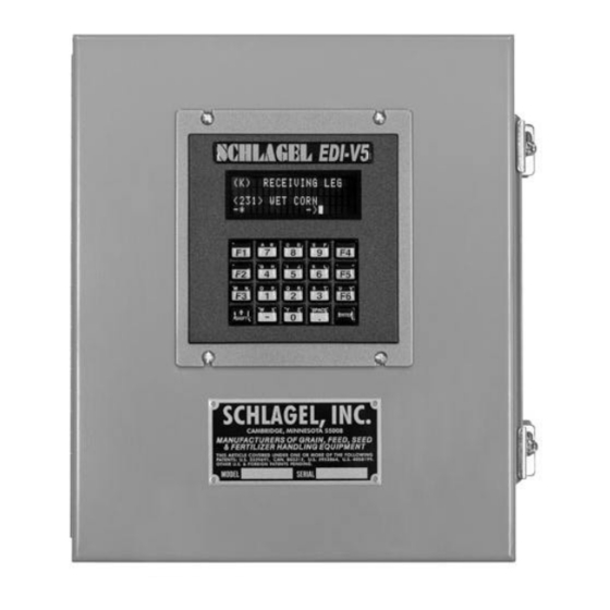
- Page 9 The following changes were made to the default O screen: PERATING Line 1 The caption on this line has been changed from “SCHLAGEL, INC.” to “RECEIVING LEG”. Line 2 This line is used for system alerts and information and cannot be modified.
-
Page 10: Access Number
SCHLAGEL, INC. SCHLAGEL, INC. EDI - V5 CONTROL Changing the Line 1 caption is a good example of using the special access codes Modify Line and character programming so we will explain all of the details here. (Access code 8004) At the O screen press 8004 Enter. - Page 11 SCHLAGEL, INC. SCHLAGEL, INC. EDI - V5 CONTROL The last screen allows the assignment of a logical name for this duct. Use the same procedure as explained above for editing the caption. Up to 14 characters may be entered. When finished, press the Enter key. The display will return to the screen showing the new information.
- Page 12 ACCESS CODE DESCRIPTION Two access codes have been explained previously, 8004 and 5993. Using these codes allowed changes to the configuration and operation of the EDI-v5 control. There are other access codes used to change the operation of the distributor. Most of these must be used with caution because they can adversely affect reliable operation of the distributor.
- Page 13 PERATING Many of the options shown in the chart are used for enabling auxiliary devices to the EDI-V5 control. Most of these must be used with caution because they can adversely affect reliable operation of the distributor. Please contact our technical support group if you are unsure of how to use these options.
- Page 14 SCHLAGEL, INC. SCHLAGEL, INC. EDI - V5 CONTROL Note: The following codes are for controls with firmware revision EDI-V5.100.5 or earlier. It is possible that some may be elimitated or changed in future revisions. EDI-V5 OPTIONS Option Name Range Default...
-
Page 15: Positioning Error
EDI - V5 CONTROL SCREEN ALERTS AND ALARMS The EDI-V5 control continuously monitors the distributor for abnormal behavior and will notify the operator when a detectable error occurs. The notification is displayed on Line 2 of the display. Various interfaces are available to activate audible or visual alarms, or to notify PLCs or other computer equipment of the error. - Page 16 SCHLAGEL, INC. SCHLAGEL, INC. EDI - V5 CONTROL EDI-V5 Accessories UIO Interface Module The UIO is a multi-function interface to the EDI control. It can act as a digital I/O device or a network scanner to combine multiple EDI controls and communicate with a PLC via protocols such as Ethernet/IP, Modbus- RTU, Modbus/TCP and DF1.
Need help?
Do you have a question about the EDI-V5 CONTROL and is the answer not in the manual?
Questions and answers